EP1065497A2 - Procédé polarimétrique ainsi que son utilisation pour l'analyse d'urine - Google Patents
Procédé polarimétrique ainsi que son utilisation pour l'analyse d'urine Download PDFInfo
- Publication number
- EP1065497A2 EP1065497A2 EP00113575A EP00113575A EP1065497A2 EP 1065497 A2 EP1065497 A2 EP 1065497A2 EP 00113575 A EP00113575 A EP 00113575A EP 00113575 A EP00113575 A EP 00113575A EP 1065497 A2 EP1065497 A2 EP 1065497A2
- Authority
- EP
- European Patent Office
- Prior art keywords
- specimen
- vibration
- plane
- polarimetry
- light
- Prior art date
- Legal status (The legal status is an assumption and is not a legal conclusion. Google has not performed a legal analysis and makes no representation as to the accuracy of the status listed.)
- Granted
Links
- 0 *CCC1=CC=CC1 Chemical compound *CCC1=CC=CC1 0.000 description 3
Images


Classifications
-
- G—PHYSICS
- G01—MEASURING; TESTING
- G01N—INVESTIGATING OR ANALYSING MATERIALS BY DETERMINING THEIR CHEMICAL OR PHYSICAL PROPERTIES
- G01N21/00—Investigating or analysing materials by the use of optical means, i.e. using sub-millimetre waves, infrared, visible or ultraviolet light
- G01N21/17—Systems in which incident light is modified in accordance with the properties of the material investigated
- G01N21/21—Polarisation-affecting properties
Definitions
- the present invention relates to a method of polarimetry for use in the identification, examination on purity, determination of the concentration and the like of a solute in a liquid specimen, and a method of urinalysis using the same.
- a polarimeter is employed as an optical rotation detecting type saccharimeter for detecting the concentrations of fructose, sucrose, glucose, and the like contained in an aqueous solution. It can also determine especially the concentrations of optical active substances such as glucose and protein in a urine. Therefore, it is expected to come into wide use as a urinalysis equipment which requires no consumable articles such as test papers.
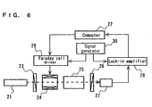
- FIG. 6 shows a conceptual constitution of one example of conventional polarimeters.
- the polarimeter is for determining the magnitude of spontaneous optical rotatory power, i.e., an angle of rotation attributed to a spontaneous optical rotatory power of a spontaneous optical active substance in a specimen to be detected.
- the angle of spontaneous optical rotation is determined based on an angle of magnetorotation (compensated value) by an optical Faraday effect when the spontaneous optical rotation attributed to the spontaneous optical active substance is canceled (compensated) by the magnetorotation.
- a semiconductor laser module 21 configured with a sodium lamp, a band-pass filter, a lens, a slit, and the like projects a substantially parallel light composed of a sodium D ray having a wavelength of 589 nm.
- a polarizer 23 transmits only a component that has a specific plane of vibration out of the light projected from the semiconductor laser module 21.
- a sample cell 25 for holding a specimen to be detected has a pair of mutually opposing transparent transmission surfaces, and is arranged so that the light projected from the semiconductor laser module 21 can transmit through the inside thereof.
- An analyzer 26 transmits only a component that has another specific plane of vibration out of the light transmitted through the sample cell 25.
- the relative angle ⁇ formed between the transmission axis of the polarizer 23 and the transmission axis of the analyzer 26 is fixed at ⁇ /2.
- a photosensor 27 detects the component transmitted through the analyzer 26 out of the light projected from the semiconductor laser module 21.
- a Faraday cell 24 modulates and controls the plane of vibration of the light projected from the semiconductor laser module 21 based on a modulation signal outputted from a signal generator 30 and a control signal outputted from a computer 22.
- the Faraday cell 24 is driven by a Faraday cell driver 29.
- a lock-in amplifier 28 performs a phase sensitive detection on the output signal from the photosensor 27 by using the modulation signal outputted from the signal generator 30 as a reference signal.
- the computer 22 calculates the angle of rotation attributed to the specimen to be detected accommodated in the sample cell 25 based on the control signal, and the output signal from the lock-in amplifier 28.
- the Faraday cell 24 modulates the plane of vibration of the light projected from the semiconductor laser module 21 and transmitted through the polarizer 23 with an amplitude of " ⁇ " and an angular frequency of " ⁇ ".
- the equation (3) indicates that the intensity "I" of the light detected by the photosensor 27 does not contain the frequency component ⁇ of the modulation signal alone.
- This point is the extinction point.
- the value of " ⁇ ” when "S” becomes zero corresponds to the angle " ⁇ ” of rotation.
- the relation between the intensity of the component with an angular frequency of ⁇ and the relative angle formed between the transmission axis of the polarizer and the transmission axis of the analyzer is expressed by a linear function in the vicinity of the extinction point.
- the extinction point is determined from a linear regression formula (regression line) derived from the mutually different three or more relative angles and the intensities of the components whose angular frequencies are ⁇ at respective relative angles.
- the present invention provides, as a first embodiment, a method of polarimetry for allowing a light to be incident upon a specimen to be detected containing a spontaneous optical active substance, and determining an optical rotation attributed to the spontaneous optical active substance when the light transmits through the specimen, comprising the steps of:
- step (a) it is effective that the relative angle is varied by continuously rotating the plane of vibration of the polarized light incident upon the specimen.
- step (a) it is also effective that the relative angle is varied by discretely changing the plane of vibration of the polarized light incident upon the specimen.
- step (d) it is effective that a linear regression formula is formed based on the data by using the relative angle as a criterion variable and using the intensity of the component with an angular frequency of ⁇ as a dependent variable, and the angle of rotation attributed to the specimen is calculated based on the obtained regression formula.
- step (a) it is also effective that the relative angle is varied by rotating the plane of vibration of the polarized light incident upon the specimen by an optical Faraday effect.
- a linear regression formula is formed based on the data by using a magnitude of a magnetic field for obtaining the relative angle or a current amount for generating the magnetic field as a criterion variable and using the intensity of the component with an angular frequency of ⁇ as a dependent variable, and the angle of rotation attributed to the specimen is calculated based on the obtained regression formula.
- the present invention also provides, as a second embodiment, a method of polarimetry for allowing a light to be incident upon a specimen to be detected containing a spontaneous optical active substance and a magneto-optical active substance, and applying a magnetic field to the specimen, thereby rotating a plane of vibration of the light transmitting though the specimen by an optical Faraday effect, and determining an optical rotation due to the spontaneous optical active substance when the light transmits through the specimen based on the magnitude of rotation of the light caused by the application of the magnetic field, comprising the steps of :
- step (a) it is effective that the plane of vibration of the light is continuously rotated by the optical Faraday effect.
- step (a) it is also effective that the plane of vibration of the light is discretely changed by the optical Faraday effect.
- step (d') it is effective that, a linear regression formula is formed based on the data, by using the magnitude of the magnetic field or the current amount for generating the magnetic field as a criterion variable and using the intensity of the component with an angular frequency of ⁇ as a dependent variable, and that an angle of rotation attributed to the specimen is calculated based on the regression formula obtained.
- the regression formula is calculated by using a least squares method.
- a specimen to be detected is a urine
- a first method of polarimetry according to the present invention is a method of polarimetry for allowing a light to be incident upon a specimen to be detected containing a spontaneous optical active substance, and determining the optical rotation due to the spontaneous optical active substance when the light transmits through the specimen. comprising the steps of:
- the relative angle is not required to be directly used.
- the magnitude of the magnetic field for obtaining the relative angle, or the amount of current for generating the magnetic field may also be used in place of the relative angle. If the magnitude of the magnetic field or the amount of current when the extinction point appears is found, it is possible to easily calculate the angle of rotation attributed to the specimen using a known formula.
- the relative angle formed between the plane of vibration of the light incident upon the specimen and the plane of vibration of the light detected by the photosensor may be varied by rotating either one plane of vibration.
- the plane of vibration of the incident light may be continuously rotated.
- the plane of vibration of the incident light may also be discretely varied.
- the configuration of a circuit to be used can be simplified because of no necessity for continuously varying " ⁇ " shown in the respective formulae. Further, it is possible to predetermine wide concentration range of the specimen because of no necessity for directly determining the extinction point.
- the present invention described above can also be applied to the measuring method in which the angle of rotation is determined based on the magnitude of magnetorotation due to the optical Faraday effect attributed to the magneto-optical active substance in the specimen, caused by directly applying a magnetic field to the specimen.
- a second method of polarimetry is a method of polarimetry for allowing a light to be incident upon a specimen to be detected containing a spontaneous optical active substance and a magneto-optical active substance and applying a magnetic field to the specimen, thereby rotating the plane of vibration of the light transmitting though the specimen by the optical Faraday effect, and determining the optical rotation due to the spontaneous optical active substance when the light transmits through the specimen based on the magnitude of rotation of the light caused by the application of the magnetic field, comprising the steps of:
- a linear regression formula is formed based on a combination of the magnitude of the magnetic field or the amount of current, and the intensity of the component whose angular frequency is ⁇ , by using the one as a variable for the other.
- the angle of rotation attributed to the specimen can be calculated based on the regression formula thus obtained.
- a linear regression formula is calculated by using the magnitude of the magnetic field or the amount of current for generating the magnetic field as a criterion variable, and using the intensity of the component whose angular frequency is ⁇ as a dependent variable. Then, the angle of rotation attributed to the specimen can be calculated based on the regression formula thus obtained.
- the magnitude of rotation of the light due to the optical Faraday effect may be continuously or discretely varied.
- the reliability of the regression formula can be evaluated using the sum of squares of residuals "S E " shown in the following equation (6) as an index. Then, when it is lower than a predetermined value, the angle of rotation obtained may be estimated as being effective. Consequently, it is possible to conduct the measurement with a higher reliability with eliminating results which have received the influences of noises.
- the influences of noises mixed into the signal can also be reduced by increasing the number of the measurement points.
- the data for every measurement point can also be checked up with the regression formula calculated from the previously obtained data to determine whether the data at the measurement point is employed or eliminated.
- the method of polarimetry according to the present invention can be applied to a urinalysis for detecting the concentrations of spontaneous optical active substances such as glucose and albumin contained in a urine used as the specimen.
- FIG. 1 schematically shows the configuration of a polarimeter of this example according to the present invention.
- a semiconductor laser module 1 projects a substantially parallel light having a wavelength of 780 nm and an intensity of 3.0 mW.
- a polarizer 3 transmits only a specific polarized component having a plane of vibration coincident with the transmission axis thereof, for example, a component having a plane of vibration parallel to the plane of a sheet of paper, out of the light projected from the semiconductor laser module 1.
- a Faraday cell 4 is provided in the back of the polarizer 3.
- the Faraday cell 4 comprises a light transmitting core member made of, for example, a flint glass, and a solenoid coil for generating a magnetic field along the advancing direction of the light passing through the core member.
- a Faraday cell driver 9 superimposes a modulation signal for modulating a magnetic field generated on a control signal for generating the magnetic field in the Faraday cell 4, and outputs it to the Faraday cell 4.
- the Faraday cell 4 generates a magnetic field by a signal from the Faraday cell driver 9, and rotates the plane of vibration of the light transmitting therethrough due to the optical Faraday effect.
- a sample cell 5 for accommodating a specimen is arranged so that the light projected by the semiconductor laser module 1 and transmitted through the polarizer 3 and the Faraday cell 4 transmits through the inside thereof.
- the substantial optical path length of the sample cell 5 is 50 mm.
- An analyzer 6 is arranged with the polarizer 3 in a so-called crossed nicols state, and selectively transmits the light of the component having a plane of vibration orthogonal to that of the light transmitting through the polarizer 3.
- a photosensor 7 detects the light transmitted through the analyzer 6.
- a preamplifier 8 amplifies the output from the photosensor 7, and outputs it to a lock-in amplifier 11.
- a signal generator 10 outputs a modulation signal to the Faraday cell driver 9.
- the lock-in amplifier 11 conducts a phase sensitive detection on the output signal from the preamplifier 8 by using the modulation signal outputted to the Faraday cell 4 as a reference signal, and outputs the signal "S" expressed as the equation (5) to a computer 12.
- the computer 12 outputs a control signal to the Faraday cell driver 9, while calculating the angle of rotation based on the output signal from the lock-in amplifier 11.
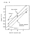
- angles of rotation of pure water and a glucose aqueous solution with a concentration of 1000 mg/dl were measured, respectively, by using the aforesaid polarimeter.
- the control current is supplied to the solenoid coil of the Faraday cell 4 for forming a magnetic field. Therefore, the magnitude of rotation of the plane of vibration occurring in the light transmitting through the Faraday cell 4 at this current value coincides with the angle of rotation attributed to a spontaneous optical active substance (the magnitude of spontaneous optical rotation).
- the time constant of the lock-in amplifier 11, that is, the integral action time of the detection signal was set as follows. First, the time constant was set to be sufficiently shorter as compared with the sweep time, about 3 milliseconds, which was longer than the period of the modulation signal, and the control current was swept to obtain a linear characteristic curve showing the relation between the control current and the output signal "S" from the lock-in amplifier 11 as shown in FIG. 2. Then, by using a time constant of 100 milliseconds given immediately before deviating from the previously obtained curve, the time constant being determined by gradually increasing the time constant while seeking the similar relation, the following measurement was carried out.
- the wording "deviating" denotes "a reduction in gradient of the curve".
- the characteristic curve showing the relation between the control signal and the signal "S” is a straight line as shown in the equation (5) in principle, it will not be a straight line because of the mixing of various noises in actuality.
- the control currents when the signal "S" becomes zero are read from the characteristic curve actually obtained are 0.002 A and 0.05 A for the pure water and the glucose aqueous solution, respectively. That is, there is observed the error due to the mixing of a noise.
- Control current [A]
- Signal "S” [V] Pure water Glucose aqueous solution -0.04 -0.82 -1.85 0 0.05 -0.92 0.04 0.78 -0.26
- the sum of squares of residuals is found to be 3.27 ⁇ 10 -3 from the regression line shown in the equation (9) and the data for the pure water shown in Table 1. Meanwhile, the sum of squares of residuals is found to be 1.22 ⁇ 10 -2 from the regression line shown in the equation (9) and the data for the glucose aqueous solution shown in Table 1.
- the control current "X" when the output signal "S" from the lock-in amplifier 11, indicated with "Y", becomes zero is 0.0482 A. Comparison of this value with the predetermined value indicates that there is obviously observed the influence of mixing of a noise on the calculated value. The sum of squares of residuals at this time is 8.62 ⁇ 10 -2 . This value is obviously greater than the value obtained by using the data shown in Table 1, indicating a low fit with respect to the regression line.
- the sum of squares of residuals is used as an index for evaluating the reliability of the regression formula, in other words, the fit between the regression formula and the measured data. For example, if this value is greater than a predetermined value, the error factor, i.e., noise is considered to be contained in the measured data in an amount exceeding the allowable level, and the measurement is nullified to conduct another measurement. Consequently, a measurement with high accuracy can be ensured.
- the error factor i.e., noise is considered to be contained in the measured data in an amount exceeding the allowable level
- the measurement is nullified to conduct another measurement. Consequently, a measurement with high accuracy can be ensured.
- the measurement may be nullified.
- FIG. 3 A polarimeter of this example according to the present invention is shown in FIG. 3.
- the polarimeter of this example magneto-optically rotates the light projected from the semiconductor laser module 1 by a solenoid coil 20 wound around a sample cell 15 in place of the Faraday cell 4 used therefor in Example 1.
- the substantial optical path length of the sample cell 15 is 50 mm as that of Example 1.
- a driver 19 outputs a control current with a modulation signal superimposed thereon to the solenoid coil 20 as the Faraday cell driver 9 used in Example 1.
- Other constitutional elements function in the same manner as those of the polarimeter of Example 1.
- angles of rotation attributed to pure water and glucose aqueous solutions respectively with concentrations of 1000 mg/dl and 2000 mg/dl were determined in the following manner by the use of the polarimeter of this example.
- control current varied discretely as -1.5 A, 0 A, and 1.5 A in 1.5 A intervals for every second was supplied to the solenoid coil 20 after superimposing a modulation signal with an amplitude of 0.001 A and a frequency of 1.3 kHz thereon. It is noted that the time constant of the lock-in amplifier 11 was set at 100 milliseconds.
- Control current [A] Signal "S” [V] Pure water Glucose aqueous solution 1000mg/dl Glucose aqueous solution 2000mg/dl -1.5 -0.304 -0.480 -0.700 0 0.040 -0.205 -0.320 1.5 0.290 0.107 -0.085
- control currents when the signal "S" becomes zero were calculated from the regression lines and are -0.0438 A for the pure water, and 0.985 A and 1.80 A for the glucose aqueous solutions with concentrations of 1000 mg/dl and 2000 mg/dl, respectively.
- the correlation coefficient "R” with respect to the regression lines obtained was calculated and was 0.996 for the pure water.
- the correlation coefficients for the glucose aqueous solutions with concentrations of 1000 mg/dl and 2000 mg/dl were 0.999 and 0.991, respectively. These values serve as criteria for the fit thereof with their respective regression lines. This indicates that, the closer to 1 the absolute value of "R" is, the higher the fit between the data obtained and the regression line is.
- the correlation coefficient "R" is smaller than a prescribed value, for example, when R ⁇ 0.995, a high measuring accuracy can be obtained by nullifying the measured results.
- Example 1 since the overall time taken to sweep the control current is required to be sufficiently longer as compared with the time constant of the lock-in amplifier, a longer time is required for measurement in order to ensure a high S/N ratio. In contrast, according to this example, it is sufficient if the time between the start of supplying the control current and the determination of the signal "S" value at each discrete measuring point is set to be 7 to 8 times larger than the time constant of the lock-in amplifier, and a measurement with high accuracy is achieved for a shorter time.
- the angle of rotation can be measured with high accuracy and for a shorter time for specimens with a wider range of concentrations. Further, by detecting and eliminating the measured results with large errors, the measurement is ensured to have accuracy.
- a description will be given to a method of urinalysis. i.e., a method of determining a glucose concentration in a urine or a urine sugar value utilizing the method of polarimetry according to Example 2.
- the angles of rotation were determined under the same conditions as in Example 2 using the polarimeter of FIG. 3 used in Example 2 for urines 1 and 2 which had been previously determined by means of a urinalysis equipment to both have a concentration of albumin, i.e., protein in the urine of 10 mg/dl or less, and have glucose concentrations of 450 mg/dl and 655 mg/dl, respectively.
- albumin i.e., protein in the urine
- angles of rotation were additionally determined in the same manner for pure water and a glucose aqueous solution with a concentration of 1000 mg/dl. These results were used as standard for determining the glucose concentration.
- Control current [A] Signal "S” [V] Urine 1 Urine 2 Pure water Glucose aqueous solution 1000mg/dl -1.5 -0.380 -0.175 -0.304 -0.480 0 -0.0722 -0.0365 0.040 -0.205 1.5 0.175 0.0660 0.290 0.107
- control currents when the signal "S" becomes zero are found from these regression lines to be 0.499 A and 0.604 A for the urine 1 and the urine 2, respectively.
- the glucose concentrations i.e., urine sugar values are found to be 484 mg/dl and 590 mg/dl for the urines 1 and 2, respectively.
- Table 5 shows the sums of squares of residuals "S E " between the measured data and the regression formulae, standardized sums of squares of residuals "D” shown in the equation (8), and the correlation coefficients "R".
- the “D” is obtained by dividing the sum of squares of residuals "S E “ by the sum of squares of the dependent variable "Y” value (calculated value of the signal "S"), which is obtained by substituting the data of the control current amount into the criterion variable "X" of the regression line obtained.
- the comparison between the correlation coefficients indicates that the accuracy of the regression formula for the urine 1 is higher than that of the urine 2.
- a method of polarimetry and a method of urinalysis which are capable of preventing the mixing of an error feared in a conventional method of polarimetry, in which the extinction point when the signal "S" becomes zero must be found while measuring the signal in a certain point.
- the method of polarimetry and the method of urinalysis according to the present invention can perform a stable and highly accurate measurement in a short time.
Landscapes
- Physics & Mathematics (AREA)
- Health & Medical Sciences (AREA)
- Life Sciences & Earth Sciences (AREA)
- Chemical & Material Sciences (AREA)
- Analytical Chemistry (AREA)
- Biochemistry (AREA)
- General Health & Medical Sciences (AREA)
- General Physics & Mathematics (AREA)
- Immunology (AREA)
- Pathology (AREA)
- Investigating Or Analysing Materials By Optical Means (AREA)
- Investigating Or Analysing Biological Materials (AREA)
Applications Claiming Priority (2)
| Application Number | Priority Date | Filing Date | Title |
|---|---|---|---|
| JP18427299 | 1999-06-29 | ||
| JP18427299 | 1999-06-29 |
Publications (3)
| Publication Number | Publication Date |
|---|---|
| EP1065497A2 true EP1065497A2 (fr) | 2001-01-03 |
| EP1065497A3 EP1065497A3 (fr) | 2002-04-24 |
| EP1065497B1 EP1065497B1 (fr) | 2005-06-01 |
Family
ID=16150426
Family Applications (1)
| Application Number | Title | Priority Date | Filing Date |
|---|---|---|---|
| EP00113575A Expired - Lifetime EP1065497B1 (fr) | 1999-06-29 | 2000-06-27 | Procédé polarimétrique ainsi que son utilisation pour l'analyse d'urine |
Country Status (3)
| Country | Link |
|---|---|
| US (1) | US6620622B1 (fr) |
| EP (1) | EP1065497B1 (fr) |
| DE (1) | DE60020453T2 (fr) |
Cited By (7)
| Publication number | Priority date | Publication date | Assignee | Title |
|---|---|---|---|---|
| WO2003029790A1 (fr) * | 2001-10-01 | 2003-04-10 | Georgia Tech Research Corporation | Detecteur chiral a haut rendement et procedes pour sa mise en oeuvre |
| EP1202044A3 (fr) * | 2000-10-24 | 2004-07-28 | Matsushita Electric Industrial Co., Ltd. | Procédé polarimétrique |
| WO2006004731A3 (fr) * | 2004-06-30 | 2006-04-13 | Stheno Corp | Systemes et procedes d'heterodynage chiro-optique |
| US7502111B2 (en) | 2003-10-10 | 2009-03-10 | Stheno Corporation | Differential optical technique for chiral analysis |
| US7590196B2 (en) | 2004-05-04 | 2009-09-15 | Spectra Analysis, Inc. | Chiral mixture detection system using double reference lock-in detector |
| CN101852721A (zh) * | 2010-05-18 | 2010-10-06 | 南京邮电大学 | 两种溶质透明混合溶液浓度检测装置 |
| CN103884658A (zh) * | 2014-03-27 | 2014-06-25 | 上海理工大学 | 一种基于质心算法的led调频多波长旋光仪及测量方法 |
Families Citing this family (8)
| Publication number | Priority date | Publication date | Assignee | Title |
|---|---|---|---|---|
| JP4606543B2 (ja) * | 2000-04-13 | 2011-01-05 | パナソニック株式会社 | 光学特性計測装置における被検溶液量確認方法および計測系制御方法 |
| JP4523143B2 (ja) * | 2000-11-10 | 2010-08-11 | シチズンホールディングス株式会社 | 濃度測定装置及び糖度測定装置 |
| US7411675B2 (en) * | 2003-03-28 | 2008-08-12 | Citizen Holdings Co., Ltd. | Optical rotation angle measuring apparatus |
| WO2006004730A1 (fr) * | 2004-06-30 | 2006-01-12 | Stheno Corporation | Systemes et procedes permettant d'accorder automatiquement un circuit resonant |
| WO2008002981A2 (fr) * | 2006-06-28 | 2008-01-03 | President And Fellows Of Harvard College | Refractomètre à biréfringence circulaire : procédé et appareil de mesure de l'activité optique |
| JP5783342B1 (ja) * | 2014-03-20 | 2015-09-24 | 富士ゼロックス株式会社 | 光学活性物質の濃度算出システム、光学活性物質の濃度算出システムの製造方法及びプログラム |
| US10702197B2 (en) * | 2016-07-26 | 2020-07-07 | The Texas A&M University System | Dual amplitude modulation and polarization frequency modulation as well as compensation for noninvasive glucose monitoring |
| US10126172B1 (en) * | 2017-10-16 | 2018-11-13 | King Fahd University Of Petroleum And Minerals | Faraday rotator device |
Family Cites Families (5)
| Publication number | Priority date | Publication date | Assignee | Title |
|---|---|---|---|---|
| US3312141A (en) | 1962-04-23 | 1967-04-04 | Applied Physics Corp | System for measuring optical activity of materials |
| DE58903504D1 (de) * | 1988-07-19 | 1993-03-25 | Siemens Ag | Verfahren zur messung der konzentration optisch aktiver substanzen und anordnung zur durchfuehrung des verfahrens. |
| EP1300670A3 (fr) * | 1995-11-16 | 2003-10-29 | Matsushita Electric Industrial Co., Ltd. | Procédé de mesure de l'angle de rotation et polarimètre |
| JP3308173B2 (ja) * | 1996-11-07 | 2002-07-29 | 松下電器産業株式会社 | 尿検査方法およびそれに用いる尿検査装置 |
| TW407201B (en) * | 1997-09-09 | 2000-10-01 | Matsushita Electric Industrial Co Ltd | Sample cell for polarimetry, polarimeter, and polarimetry |
-
2000
- 2000-06-27 EP EP00113575A patent/EP1065497B1/fr not_active Expired - Lifetime
- 2000-06-27 DE DE60020453T patent/DE60020453T2/de not_active Expired - Fee Related
- 2000-06-27 US US09/604,406 patent/US6620622B1/en not_active Expired - Fee Related
Cited By (10)
| Publication number | Priority date | Publication date | Assignee | Title |
|---|---|---|---|---|
| EP1202044A3 (fr) * | 2000-10-24 | 2004-07-28 | Matsushita Electric Industrial Co., Ltd. | Procédé polarimétrique |
| US6934023B2 (en) | 2000-10-24 | 2005-08-23 | Matsushita Electric Industrial Co., Ltd. | Method of polarimetry |
| WO2003029790A1 (fr) * | 2001-10-01 | 2003-04-10 | Georgia Tech Research Corporation | Detecteur chiral a haut rendement et procedes pour sa mise en oeuvre |
| US7502111B2 (en) | 2003-10-10 | 2009-03-10 | Stheno Corporation | Differential optical technique for chiral analysis |
| US7590196B2 (en) | 2004-05-04 | 2009-09-15 | Spectra Analysis, Inc. | Chiral mixture detection system using double reference lock-in detector |
| WO2006004731A3 (fr) * | 2004-06-30 | 2006-04-13 | Stheno Corp | Systemes et procedes d'heterodynage chiro-optique |
| US7405826B2 (en) | 2004-06-30 | 2008-07-29 | Gibbs Phillip R | Systems and methods for chiroptical heterodyning |
| CN101852721A (zh) * | 2010-05-18 | 2010-10-06 | 南京邮电大学 | 两种溶质透明混合溶液浓度检测装置 |
| CN101852721B (zh) * | 2010-05-18 | 2012-06-27 | 南京邮电大学 | 两种溶质透明混合溶液浓度检测装置 |
| CN103884658A (zh) * | 2014-03-27 | 2014-06-25 | 上海理工大学 | 一种基于质心算法的led调频多波长旋光仪及测量方法 |
Also Published As
| Publication number | Publication date |
|---|---|
| EP1065497A3 (fr) | 2002-04-24 |
| US6620622B1 (en) | 2003-09-16 |
| DE60020453D1 (de) | 2005-07-07 |
| EP1065497B1 (fr) | 2005-06-01 |
| DE60020453T2 (de) | 2006-05-11 |
Similar Documents
| Publication | Publication Date | Title |
|---|---|---|
| EP0805352B1 (fr) | Procede et appareil d'analyse d'urine, procede de mesure de la rotation optique et polarimetre | |
| EP1065497B1 (fr) | Procédé polarimétrique ainsi que son utilisation pour l'analyse d'urine | |
| EP1146329A1 (fr) | Méthode pour vérifier la quantité d'un dissolvant, pour controller le système de mesurage et pour mesurer la concentration d'un dissolvant avec un appareil de mesurage des caractéristiques optiques | |
| CN113758877B (zh) | 一种频域量子弱测量生物分子传感器及其测量方法 | |
| JP3072040B2 (ja) | 旋光度測定方法、旋光計、尿検査方法及び尿検査装置 | |
| EP0902270B1 (fr) | Cellule d'échantillon pour polarimétrie et polarimètre | |
| EP0845673B1 (fr) | Méthode pour mesurer la concentration d'un constituant spécifique | |
| JPH0228541A (ja) | 光式濃度検出装置 | |
| WO1999030132A1 (fr) | Procede de production d'une electrode destinee a des cellules secondaires electrolytiques non aqueuses | |
| Wang | Measurement of circular and linear birefringence in chiral media and optical materials using the photoelastic modulator | |
| JPH08146066A (ja) | 電気信号測定方法および装置 | |
| JP3415034B2 (ja) | 旋光度測定方法、濃度判定方法および濃度制御方法並びに旋光計 | |
| JP2001074649A (ja) | 旋光角測定方法および尿検査方法 | |
| JP3350877B2 (ja) | 旋光度測定方法、濃度測定方法 | |
| EP1202044A2 (fr) | Procédé polarimétrique | |
| JPH0755891A (ja) | 集積回路の試験方法および試験装置 | |
| JP3393997B2 (ja) | 液体の光学特性計測装置における計測系制御方法 | |
| JP2004279380A (ja) | 旋光度測定装置 | |
| JP2004279250A (ja) | 濃度測定装置 | |
| JPH06317518A (ja) | 二色性分散計 | |
| Galatola | Light-scattering study of Fréedericksz transitions in nematic liquid crystals | |
| JP2002131223A5 (fr) | ||
| JPH08128946A (ja) | 光学特性測定方法及び測定装置 | |
| EP1111368A1 (fr) | Procédé pour la mesure de la concentration d'une solution et procédé pour l'analyse d'urine utilisant ceux-ci | |
| JP3872456B2 (ja) | 電界センサ |
Legal Events
| Date | Code | Title | Description |
|---|---|---|---|
| PUAI | Public reference made under article 153(3) epc to a published international application that has entered the european phase |
Free format text: ORIGINAL CODE: 0009012 |
|
| AK | Designated contracting states |
Kind code of ref document: A2 Designated state(s): AT BE CH CY DE DK ES FI FR GB GR IE IT LI LU MC NL PT SE Kind code of ref document: A2 Designated state(s): DE FR GB |
|
| AX | Request for extension of the european patent |
Free format text: AL;LT;LV;MK;RO;SI |
|
| PUAL | Search report despatched |
Free format text: ORIGINAL CODE: 0009013 |
|
| RIC1 | Information provided on ipc code assigned before grant |
Free format text: 7G 01N 21/21 A, 7G 01N 33/493 B |
|
| AK | Designated contracting states |
Kind code of ref document: A3 Designated state(s): AT BE CH CY DE DK ES FI FR GB GR IE IT LI LU MC NL PT SE |
|
| AX | Request for extension of the european patent |
Free format text: AL;LT;LV;MK;RO;SI |
|
| 17P | Request for examination filed |
Effective date: 20020528 |
|
| AKX | Designation fees paid |
Free format text: DE FR GB |
|
| 17Q | First examination report despatched |
Effective date: 20031114 |
|
| GRAP | Despatch of communication of intention to grant a patent |
Free format text: ORIGINAL CODE: EPIDOSNIGR1 |
|
| GRAS | Grant fee paid |
Free format text: ORIGINAL CODE: EPIDOSNIGR3 |
|
| GRAA | (expected) grant |
Free format text: ORIGINAL CODE: 0009210 |
|
| AK | Designated contracting states |
Kind code of ref document: B1 Designated state(s): DE FR GB |
|
| REG | Reference to a national code |
Ref country code: GB Ref legal event code: FG4D |
|
| REG | Reference to a national code |
Ref country code: IE Ref legal event code: FG4D |
|
| REF | Corresponds to: |
Ref document number: 60020453 Country of ref document: DE Date of ref document: 20050707 Kind code of ref document: P |
|
| ET | Fr: translation filed | ||
| PLBE | No opposition filed within time limit |
Free format text: ORIGINAL CODE: 0009261 |
|
| STAA | Information on the status of an ep patent application or granted ep patent |
Free format text: STATUS: NO OPPOSITION FILED WITHIN TIME LIMIT |
|
| 26N | No opposition filed |
Effective date: 20060302 |
|
| PGFP | Annual fee paid to national office [announced via postgrant information from national office to epo] |
Ref country code: FR Payment date: 20060608 Year of fee payment: 7 |
|
| PGFP | Annual fee paid to national office [announced via postgrant information from national office to epo] |
Ref country code: GB Payment date: 20060621 Year of fee payment: 7 |
|
| PGFP | Annual fee paid to national office [announced via postgrant information from national office to epo] |
Ref country code: DE Payment date: 20060622 Year of fee payment: 7 |
|
| GBPC | Gb: european patent ceased through non-payment of renewal fee |
Effective date: 20070627 |
|
| REG | Reference to a national code |
Ref country code: FR Ref legal event code: ST Effective date: 20080229 |
|
| PG25 | Lapsed in a contracting state [announced via postgrant information from national office to epo] |
Ref country code: DE Free format text: LAPSE BECAUSE OF NON-PAYMENT OF DUE FEES Effective date: 20080101 |
|
| PG25 | Lapsed in a contracting state [announced via postgrant information from national office to epo] |
Ref country code: GB Free format text: LAPSE BECAUSE OF NON-PAYMENT OF DUE FEES Effective date: 20070627 |
|
| PG25 | Lapsed in a contracting state [announced via postgrant information from national office to epo] |
Ref country code: FR Free format text: LAPSE BECAUSE OF NON-PAYMENT OF DUE FEES Effective date: 20070702 |