EP1065509A2 - Diagnosevorrichtung für eine Mehrantennenanordnung - Google Patents
Diagnosevorrichtung für eine Mehrantennenanordnung Download PDFInfo
- Publication number
- EP1065509A2 EP1065509A2 EP00112549A EP00112549A EP1065509A2 EP 1065509 A2 EP1065509 A2 EP 1065509A2 EP 00112549 A EP00112549 A EP 00112549A EP 00112549 A EP00112549 A EP 00112549A EP 1065509 A2 EP1065509 A2 EP 1065509A2
- Authority
- EP
- European Patent Office
- Prior art keywords
- antenna
- signal
- test
- control unit
- diagnostic device
- Prior art date
- Legal status (The legal status is an assumption and is not a legal conclusion. Google has not performed a legal analysis and makes no representation as to the accuracy of the status listed.)
- Granted
Links
Images
Classifications
-
- H—ELECTRICITY
- H04—ELECTRIC COMMUNICATION TECHNIQUE
- H04B—TRANSMISSION
- H04B17/00—Monitoring; Testing
- H04B17/0082—Monitoring; Testing using service channels; using auxiliary channels
-
- H—ELECTRICITY
- H04—ELECTRIC COMMUNICATION TECHNIQUE
- H04B—TRANSMISSION
- H04B7/00—Radio transmission systems, i.e. using radiation field
- H04B7/02—Diversity systems; Multi-antenna system, i.e. transmission or reception using multiple antennas
- H04B7/04—Diversity systems; Multi-antenna system, i.e. transmission or reception using multiple antennas using two or more spaced independent antennas
- H04B7/08—Diversity systems; Multi-antenna system, i.e. transmission or reception using multiple antennas using two or more spaced independent antennas at the receiving station
-
- H—ELECTRICITY
- H04—ELECTRIC COMMUNICATION TECHNIQUE
- H04B—TRANSMISSION
- H04B17/00—Monitoring; Testing
- H04B17/0082—Monitoring; Testing using service channels; using auxiliary channels
- H04B17/0085—Monitoring; Testing using service channels; using auxiliary channels using test signal generators
-
- H—ELECTRICITY
- H04—ELECTRIC COMMUNICATION TECHNIQUE
- H04B—TRANSMISSION
- H04B17/00—Monitoring; Testing
- H04B17/0082—Monitoring; Testing using service channels; using auxiliary channels
- H04B17/0087—Monitoring; Testing using service channels; using auxiliary channels using auxiliary channels or channel simulators
Definitions
- the invention relates to a diagnostic device according to the Preamble of claim 1.
- Multi-antenna arrays with antenna diversity are a problem as far as it is concerned the differentiated inspection of the individual antenna including the condition whose electrical connection goes to the radio receiver. Except assuming that the available interfaces for connection to measuring and Test systems are often difficult to access and extensive demonization work is not known at a specific point in time, which antenna considering the switch position of the antenna diversity is activated.
- this is by measuring the Receive level at the antenna connection socket of the radio receiver not available at the moment, as is known for a diversity system, if the signal level falls below a certain predetermined value, the radio receiver automatically via a corresponding switch is placed on one of the next antennas, in which a sufficient Reception level can be determined.
- EP 0 806 849 A2 describes a circuit arrangement for functional testing mobile radio receiving systems known, which also in diversity systems can be used.
- the underlying idea is that about the A high-frequency signal is generated on the output side, which the set reception frequency of the radio receiver essentially corresponds and which is coupled in via the receiving antenna, where the level of the received signal is measured.
- a Switching signal generator can be a sequential switching of the antenna switch of a diversity processor, so that the High-frequency signal mentioned above via different antennas of the Diversity systems are coupled and the reception performance of each Antenna can be measured.
- a defined initial state too however, this system does not start the functional test.
- Another circuit arrangement for testing is known from DE 195 13 872 A1 known from multi-antenna systems, which aims to pass this test easy to design.
- the underlying idea here is about a each antenna-specific pulse train, either indirectly via the Radio receiver or is generated via an external test device, via a special converter circuit on the switch of the antenna diversity to act in such a way that in accordance with the pulse sequence mentioned a specific antenna is switched through to the radio receiver becomes.
- the pulse train can either be via the antenna cable or an intermediate frequency output of the radio receiver in the diversity system are fed in, each with an intermediate arrangement of filters, the purpose of which is to separate the test pulses from the main signals, that run over these lines. Then on the same channel a test signal is routed via which the reception conditions of the individual Antenna can be checked.
- Antenna system only two interfaces are required, namely the usual one IF input of the diversity processor and the RF output of the antenna system. These two interfaces are used to connect a test unit and a control unit, which are external devices that Can be used as part of the end-of-line inspection or at motor vehicle workshops are. There are therefore no circuit interventions in passive or active functional elements of the antenna system or the radio receiver required.
- it can be conventional diversity systems act, whose control signal in diversity mode consists of an IF signal, with FM reception is a 10.7 MHz signal that has a DC voltage component is imprinted.
- the test unit initially comprises a transmission and reception module and serves to set up an RF circuit into which the test item is to be tested Multi-antenna system is integrated.
- a transmitting antenna provided, via which a test signal generated by the test unit is emitted, which in the switched antenna of the multi-antenna system is fed in and via this again for the analysis of the test unit is forwarded.
- the test unit is in turn with a control unit Active connection, which is a signal generator, a DC voltage source and includes a noise simulator.
- the main purpose of the control unit is therein the necessary control signals for the diversity processor to make available as well as fault states in a defined manner simulate that depending on the properties and settings of the Diversity processor with the proviso that on a defined Fault switching the diversity processor to the next one Antenna of the multi-antenna system is caused.
- the diagnostic device is therefore intended, in accordance with disturbance states, which over the Control unit are generated, a targeted step forward of the diversity processor to cause, the signal received via the test unit the state of the antenna switched through including its connecting lines reproduces.
- the function test with a reset mode of the diversity processor that starts at this stage a certain known antenna, the main antenna, is on, and that after connecting in particular the control unit, in connection with a slowly applying a DC voltage to the IF control signal Diversity mode is activated without first changing the antenna becomes.
- the interference simulator can be used to coordinate test procedure to be carried out with the test unit with regard to the individual Antennas are initiated.
- the control signal is in accordance with the features of the claim 2 usually around the IF signal, i.e. with FM reception a 10.7 MHz signal.
- test signal which is generated via the test unit, can accordingly the features of claim 3 be the IF signal similar.
- test unit can in accordance with the features of claim 4 be further configured so that the respective antenna-specific measurement signals, if necessary after comparison with standard values and logged in a suitable manner Are displayed in such a way that the electrical connection paths of individual antennas can be checked if necessary.
- control unit and the test unit form a structural unit. It can be a single device, but equally can also be integrated in other test devices.
- the diagnostic device is corresponding the features of claim 6 for connection to the IF input and the RF output of such a unit is determined.
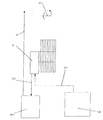
- test unit 2 denotes an external test unit, which is connected via an HF line 3 a corresponding output of the antenna amplifier 1 in connection stands.
- the test unit 2 according to the invention consists of a transmission and reception module as well as from other modules that save, register, Comparing, evaluating and, if necessary, visualizing measurement data are designed.
- test unit 2 is connected via a further HF line 4 with a transmitting antenna 5 in connection, the meaning of which will be explained in more detail below becomes.
- the control unit 6 comprises a signal generator, in particular a sine generator, a DC voltage source and a noise simulator.
- the sine generator is after Requirement of the test in the AM or in the FM area for the generation of a Frequency of 460 kHz or 10.7 MHz designed, this A DC voltage of, for example, 12 V is impressed on the intermediate frequency can be.
- the interference simulator is set up so that the this way generated IF signal can be temporarily disturbed during a deterioration in the signal-to-noise ratio within a defined period of time to simulate. This period is in agreement with the corresponding one Diversity processor settings selected so that this is shorter than the minimum dwell time with an antenna Multi-antenna arrangement. It is the essential prerequisite for that switching from one antenna to another in a defined manner next following is possible.
- a diversity system is usually based on the intermediate frequency of the receiver and a DC voltage signal controlled, the DC voltage signal is used to activate a diversity mode.
- the DC voltage signal is used to activate a diversity mode.
- the two interfaces of the antenna amplifier are thus the IF input required for the diversity system on the one hand and the otherwise intended for connection to the receiver's input socket RF output on the other hand. Only these two interfaces are thus required in accordance with the invention to diagnose the multi-antenna system perform. With the test unit 2 and the control unit 6 it can thus are external devices that are structurally separate from each other, but that can also form a unit.
- the RF connections are first used between the test unit 2, the control unit 6 and the antenna amplifier 1 manufactured.
- the diversity system is initially based on the open interfaces and the lack of a DC signal on one certain known antenna, namely the main antenna.
- About the Control unit 6 now becomes an IF signal with a level of approx. 40 dB ⁇ V are provided, in the case of FM reception with the usual Intermediate frequency of 10.7 MHz. It can be a pure one act unmodulated sine signal.
- a DC signal is sent to this IF signal now slowly impressed, so that the diversity system from Reset mode is brought into the diversity mode without first Changing the antenna takes place. This ensures that an undisturbed IF signal is fed into the diversity system.
- the multi-antenna system is in this initial phase thus a defined initial state for the following functional test in front.
- the IF signal is then briefly disturbed by the interference simulator - as already explained above - this interference via the diversity system is recognized and a transfer in a manner known per se to the next antenna following a given cycle triggers.
- the disruption only lasts for a very short time pending, switching takes place only to the immediately within a Cycle following antenna instead.
- a test signal from a defined power and in a defined frequency range via the transmitting antenna 5 radiated, which over the unplayed receiving antenna the multi-antenna arrangement arrives in the antenna amplifier 1.
- the control unit 6 Receive data from each antenna individually measured and evaluated, for example by comparison with standard data, the measurement results in can be logged or visualized in a suitable manner.
- the system according to the invention offers Diagnostic device thus the advantage that over the already existing Interfaces of an antenna amplifier with connected Diversity system with otherwise unchanged conditions an individual Testing the individual antennas of a multi-antenna system in accordance with reproducible performance data is possible. It is this way for example a particularly simple way of checking the content is possible, whether all electrical connections between the antenna structures of the Vehicle and the antenna amplifier up to the receiver are.
Landscapes
- Engineering & Computer Science (AREA)
- Computer Networks & Wireless Communication (AREA)
- Signal Processing (AREA)
- Physics & Mathematics (AREA)
- Electromagnetism (AREA)
- Radio Transmission System (AREA)
- Monitoring And Testing Of Transmission In General (AREA)
- Variable-Direction Aerials And Aerial Arrays (AREA)
- Mobile Radio Communication Systems (AREA)
Abstract
Description
Claims (7)
- Diagnosevorrichtung für eine Mehrantennenanordnung mit einem Diversity-Prozessor,
gekennzeichnet durcheine Prüfeinheit (2) sowie eine Steuereinheit (6), die in Wirkverbindung mit dem Diversity-Prozessor bringbar sind,wobei die Prüfeinheit (2) zumindest aus einem Sende- und einem Empfangsmodul, einer Sendeantenne (5) und einem Speichermodul besteht,wobei die Steuereinheit (6) zumindest aus einem Signalgenerator, einer Gleichspannungsquelle und einem Störsimulator besteht undwobei die Steuereinheit (6) zur Generierung eines Steuersignals für den Diversity-Prozessor und die Prüfeinheit (2) zur Generierung eines Testsignals sowie zum Empfang desselben über die jeweils unter Mitwirkung der Steuereinheit (6) ausgewählte Antenne der Mehrantennenanordnung bestimmt und eingerichtet sind. - Diagnosevorrichtung nach Anspruch 1,
dadurch gekennzeichnet,daß das Steuersignal ein ZF-Signal ist, dem eine Gleichspannung aufgeprägt ist. - Diagnosevorrichtung nach Anspruch 1 oder 2,
dadurch gekennzeichnet,daß das Testsignal dem ZF-Signal zumindest ähnlich ist. - Diagnosevorrichtung nach einem der Ansprüche 1 bis 3,
dadurch gekennzeichnet,daß die Prüfeinheit (2) für ein antennenspezifisches Auswerten der empfangenen Signale, zum Protokollieren und Visualisieren derselben eingerichtet ist. - Diagnosevorrichtung nach einem der vorangegangenen Ansprüche 1 bis 4,
dadurch gekennzeichnet,daß die Prüfeinheit (2) und die Steuereinheit (6) eine bauliche Einheit bilden. - Diagnosevorrichtung nach einem der vorangegangenen Ansprüche 1 bis 5,
dadurch gekennzeichnet,daß der Diversity-Prozessor mit einem Antennenverstärker (1) eine bauliche Einheit bildet, unddaß die Prüfeinheit (2) und die Steuereinheit (6) mit dem ZF-Eingang des Diversity-Prozessors sowie dem HF-Ausgang des Antennenverstärkers (1) in Verbindung bringbar sind. - Diagnosevorrichtung nach einem der vorangegangenen Ansprüche 1 bis 6,
dadurch gekennzeichnet,daß der Störsimulator der Steuereinheit (6) dahingehend eingerichtet ist, daß dem generierten Steuersignal ein Störsignal lediglich während einer solchen Zeitspanne aufgeprägt wird, die kürzer bemessen ist als die durch den Diversity-Prozessor gesteuerte Verweilzeit bei einer einzelnen Antenne des Mehrantennensystems.
Applications Claiming Priority (2)
| Application Number | Priority Date | Filing Date | Title |
|---|---|---|---|
| DE19930571A DE19930571B4 (de) | 1999-07-02 | 1999-07-02 | Diagnosevorrichtung für eine Mehrantennenanordnung |
| DE19930571 | 1999-07-02 |
Publications (3)
| Publication Number | Publication Date |
|---|---|
| EP1065509A2 true EP1065509A2 (de) | 2001-01-03 |
| EP1065509A3 EP1065509A3 (de) | 2001-01-17 |
| EP1065509B1 EP1065509B1 (de) | 2004-11-03 |
Family
ID=7913438
Family Applications (1)
| Application Number | Title | Priority Date | Filing Date |
|---|---|---|---|
| EP00112549A Expired - Lifetime EP1065509B1 (de) | 1999-07-02 | 2000-06-14 | Diagnosevorrichtung für eine Mehrantennenanordnung |
Country Status (4)
| Country | Link |
|---|---|
| US (1) | US6313799B1 (de) |
| EP (1) | EP1065509B1 (de) |
| AT (1) | ATE281652T1 (de) |
| DE (2) | DE19930571B4 (de) |
Cited By (1)
| Publication number | Priority date | Publication date | Assignee | Title |
|---|---|---|---|---|
| CN102651669A (zh) * | 2011-02-23 | 2012-08-29 | 苏州博联科技有限公司 | 一种传感器网络节点抗干扰测试系统以及测试方法 |
Families Citing this family (25)
| Publication number | Priority date | Publication date | Assignee | Title |
|---|---|---|---|---|
| DE10101173B4 (de) * | 2001-01-12 | 2006-06-29 | Audi Ag | Vorrichtung und Verfahren zur Diagnose eines Antennensystems |
| US6577268B1 (en) * | 2002-06-20 | 2003-06-10 | The United States Of America As Represented By The Secretary Of The Navy | Outboard radio signal test system and method |
| DE10338825A1 (de) * | 2003-08-21 | 2005-03-24 | Daimlerchrysler Ag | Diagnoseeinrichtung und Diagnoseverfahren für ein Mehrantennensystem |
| CN1667814B (zh) * | 2004-03-08 | 2010-10-13 | 松下电器产业株式会社 | 干扰分析方法及干扰分析装置 |
| US20060205369A1 (en) * | 2005-03-06 | 2006-09-14 | Hirschmann Car Communication Gmbh | Multiple antenna receiver system in vehicles |
| DE102005039526A1 (de) * | 2005-08-18 | 2007-02-22 | Daimlerchrysler Ag | Verfahren und Diagnosevorrichtung zur selektiven Prüfung von Empfangsantennen in einem Mehrantennensystem |
| DE102006039357B4 (de) * | 2005-09-12 | 2018-06-28 | Heinz Lindenmeier | Antennendiversityanlage zum Funkempfang für Fahrzeuge |
| DE102007017478A1 (de) * | 2007-04-13 | 2008-10-16 | Lindenmeier, Heinz, Prof. Dr. Ing. | Empfangsanlage mit einer Schaltungsanordnung zur Unterdrückung von Umschaltstörungen bei Antennendiversity |
| US7880670B2 (en) * | 2007-06-18 | 2011-02-01 | AGC Automotive | Signal measurement system and method for testing an RF component |
| EP2037593A3 (de) * | 2007-07-10 | 2016-10-12 | Delphi Delco Electronics Europe GmbH | Antennendiversityanlage für den relativ breitbandigen Funkempfang in Fahrzeugen |
| DE102007039914A1 (de) * | 2007-08-01 | 2009-02-05 | Lindenmeier, Heinz, Prof. Dr. Ing. | Antennendiversityanlage mit zwei Antennen für den Funkempfang in Fahrzeugen |
| DE102008003532A1 (de) * | 2007-09-06 | 2009-03-12 | Lindenmeier, Heinz, Prof. Dr. Ing. | Antenne für den Satellitenempfang |
| US8362783B2 (en) * | 2008-08-27 | 2013-01-29 | Agc Automotive Americas Co. | Method for verifying a completeness of an antenna |
| PT2209221T (pt) * | 2009-01-19 | 2018-12-27 | Fuba Automotive Electronics Gmbh | Sistema de recepção para a soma de sinais de antena em fase |
| DE102009011542A1 (de) * | 2009-03-03 | 2010-09-09 | Heinz Prof. Dr.-Ing. Lindenmeier | Antenne für den Empfang zirkular in einer Drehrichtung der Polarisation ausgestrahlter Satellitenfunksignale |
| DE102009023514A1 (de) * | 2009-05-30 | 2010-12-02 | Heinz Prof. Dr.-Ing. Lindenmeier | Antenne für zirkulare Polarisation mit einer leitenden Grundfläche |
| CN102854409A (zh) * | 2011-06-30 | 2013-01-02 | 鸿富锦精密工业(深圳)有限公司 | 电磁干扰测试装置 |
| US9319908B2 (en) * | 2011-10-12 | 2016-04-19 | Apple Inc. | Methods for reducing path loss while testing wireless electronic devices with multiple antennas |
| FR2987196B1 (fr) * | 2012-02-17 | 2014-04-04 | Continental Automotive France | Procede et dispositif de diagnostic d'antenne |
| CN103293393B (zh) * | 2012-02-29 | 2017-04-12 | 深圳光启创新技术有限公司 | 一种紧缩场产生装置 |
| CN103293395B (zh) * | 2012-02-29 | 2017-04-12 | 深圳光启创新技术有限公司 | 一种紧缩场产生装置 |
| CN103293394B (zh) * | 2012-02-29 | 2017-04-05 | 深圳光启创新技术有限公司 | 一种紧缩场产生装置 |
| CN103293392B (zh) * | 2012-02-29 | 2017-04-05 | 深圳光启创新技术有限公司 | 一种紧缩场产生装置 |
| US9614741B2 (en) * | 2015-07-31 | 2017-04-04 | GM Global Technology Operations LLC | Vehicle antenna system and method for determining connectivity status thereof |
| EP3748374B8 (de) * | 2019-06-06 | 2023-02-15 | Rohde & Schwarz GmbH & Co. KG | System und verfahren zur kalibrierung von funkfrequenz-testkammern |
Family Cites Families (5)
| Publication number | Priority date | Publication date | Assignee | Title |
|---|---|---|---|---|
| DE19513872B4 (de) * | 1995-04-12 | 2007-05-03 | Fuba Automotive Gmbh & Co. Kg | Verfahren und Schaltungsanordnung zum Prüfen von Kraftfahrzeug-Antennen |
| DE19618333A1 (de) * | 1996-05-07 | 1997-11-13 | Lindenmeier Heinz | Schaltungsanordnung zur Funktionsprüfung mobiler Rundfunkempfangsanlagen |
| DE19627391C1 (de) * | 1996-07-06 | 1997-12-11 | Flachglas Automotive Gmbh | Diagnoseverfahren und Diagnosesystem für Kfz-Antennenscheiben |
| JP2000049719A (ja) * | 1998-07-31 | 2000-02-18 | Harada Ind Co Ltd | マストレスアンテナ検査装置 |
| DE29911085U1 (de) | 1999-06-25 | 1999-09-02 | FUBA Automotive GmbH, 31162 Bad Salzdetfurth | Antennendiversitysystem, insbesondere für den mobilen Fernsehempfang |
-
1999
- 1999-07-02 DE DE19930571A patent/DE19930571B4/de not_active Expired - Fee Related
-
2000
- 2000-06-14 DE DE50008477T patent/DE50008477D1/de not_active Expired - Lifetime
- 2000-06-14 EP EP00112549A patent/EP1065509B1/de not_active Expired - Lifetime
- 2000-06-14 AT AT00112549T patent/ATE281652T1/de not_active IP Right Cessation
- 2000-06-27 US US09/604,949 patent/US6313799B1/en not_active Expired - Lifetime
Cited By (2)
| Publication number | Priority date | Publication date | Assignee | Title |
|---|---|---|---|---|
| CN102651669A (zh) * | 2011-02-23 | 2012-08-29 | 苏州博联科技有限公司 | 一种传感器网络节点抗干扰测试系统以及测试方法 |
| CN102651669B (zh) * | 2011-02-23 | 2016-01-20 | 苏州博联科技有限公司 | 一种传感器网络节点抗干扰测试系统以及测试方法 |
Also Published As
| Publication number | Publication date |
|---|---|
| EP1065509A3 (de) | 2001-01-17 |
| ATE281652T1 (de) | 2004-11-15 |
| DE19930571B4 (de) | 2010-04-29 |
| DE19930571A1 (de) | 2001-01-04 |
| DE50008477D1 (de) | 2004-12-09 |
| US6313799B1 (en) | 2001-11-06 |
| EP1065509B1 (de) | 2004-11-03 |
Similar Documents
| Publication | Publication Date | Title |
|---|---|---|
| EP1065509B1 (de) | Diagnosevorrichtung für eine Mehrantennenanordnung | |
| DE69501453T2 (de) | Elektronisches Informationsübertragungssystem auf stromführenden Leitungen, insbesonders für ein Kraftfahrzeug | |
| DE19627391C1 (de) | Diagnoseverfahren und Diagnosesystem für Kfz-Antennenscheiben | |
| DE3727549A1 (de) | Stoerungsdiagnosesystem fuer elektronische vorrichtungen in kraftfahrzeugen | |
| DE3936988C2 (de) | ||
| DE29911541U1 (de) | Diagnosevorrichtung für eine Mehrantennenanordnung | |
| EP0354214B1 (de) | Verfahren zur feststellung der elektrischen laufzeit von signalstrecken | |
| EP1410051B1 (de) | Verfahren und vorrichtung zur prüfung von elektrischen leitungen und/oder elektrischen verbrauchern in einem fahrzeug auf fehler | |
| EP4018600B1 (de) | Verfahren zur positionserkennung eines busteilnehmers | |
| EP1198716B1 (de) | Schaltungsanordnung und verfahren zur prüfung eines schaltdiversity-systems | |
| DE102013224809A1 (de) | Verfahren zum Testen eines Steuergeräts für ein Fahrzeug sowie entsprechendes Steuergerät, System und Fahrzeug | |
| DE19513872A1 (de) | Verfahren und Schaltungsanordnung zum Prüfen von Kraftfahrzeug-Antennen | |
| EP4018603B1 (de) | Verfahren zur positionserkennung eines busteilnehmers | |
| EP0656590B1 (de) | Messvorrichtung zum Testen der Verbindungen zwischen wenigstens zwei Baugruppen | |
| DE102009037497B4 (de) | Diagnosevorrichtung für schlüsselloses Zugangssystem | |
| DE102004059694B3 (de) | Verfahren und Anordnungen zum Prüfen einer Antennenanordnung, insbesondere eines Kraftfahrzeuges | |
| EP1430318B1 (de) | Verfahren und vorrichtung zur lokalisierung eines leitungsfehlers | |
| DE10348297B4 (de) | Prüfvorrichtung für Steuergeräte eines Kraftfahrzeugs und Verfahren zum Prüfen von Steuergeräten eines Kraftfahrzeugs | |
| DE102007007776B3 (de) | Testsystem und Verfahren zum Prüfen einer Baugruppe | |
| EP3807660B1 (de) | Verfahren und vorrichtung zum elektrischen prüfen einer elektrischen baugruppe | |
| EP3620804B1 (de) | Prüfvorrichtung für die elektrik eines lkw mit einem stecker zum einstecken in eine anhängersteckdose des lkw | |
| DE3837718A1 (de) | Vorrichtung zur pruefung der stoerfestigkeit von elektronischen geraeten oder systemen | |
| DE9317946U1 (de) | Schnittstellenkabel für Datenendeinrichtungen und Prüfeinrichtung | |
| DE4406510C1 (de) | Integrierter Schaltkreis mit einer mitintegrierten Prüfvorrichtung | |
| DE2704002A1 (de) | Tastkopf zum anschliessen an pruefstellen von logische schaltkreise enthaltenden steckbaugruppen |
Legal Events
| Date | Code | Title | Description |
|---|---|---|---|
| PUAI | Public reference made under article 153(3) epc to a published international application that has entered the european phase |
Free format text: ORIGINAL CODE: 0009012 |
|
| PUAL | Search report despatched |
Free format text: ORIGINAL CODE: 0009013 |
|
| AK | Designated contracting states |
Kind code of ref document: A2 Designated state(s): AT BE CH CY DE DK ES FI FR GB GR IE IT LI LU MC NL PT SE |
|
| AX | Request for extension of the european patent |
Free format text: AL;LT;LV;MK;RO;SI |
|
| AK | Designated contracting states |
Kind code of ref document: A3 Designated state(s): AT BE CH CY DE DK ES FI FR GB GR IE IT LI LU MC NL PT SE |
|
| AX | Request for extension of the european patent |
Free format text: AL;LT;LV;MK;RO;SI |
|
| RIC1 | Information provided on ipc code assigned before grant |
Free format text: 7G 01R 29/10 A |
|
| 17P | Request for examination filed |
Effective date: 20001215 |
|
| 17Q | First examination report despatched |
Effective date: 20010329 |
|
| AKX | Designation fees paid |
Free format text: AT BE CH CY DE DK ES FI FR GB GR IE IT LI LU MC NL PT SE |
|
| GRAP | Despatch of communication of intention to grant a patent |
Free format text: ORIGINAL CODE: EPIDOSNIGR1 |
|
| GRAP | Despatch of communication of intention to grant a patent |
Free format text: ORIGINAL CODE: EPIDOSNIGR1 |
|
| GRAS | Grant fee paid |
Free format text: ORIGINAL CODE: EPIDOSNIGR3 |
|
| GRAA | (expected) grant |
Free format text: ORIGINAL CODE: 0009210 |
|
| AK | Designated contracting states |
Kind code of ref document: B1 Designated state(s): AT BE CH CY DE DK ES FI FR GB GR IE IT LI LU MC NL PT SE |
|
| PG25 | Lapsed in a contracting state [announced via postgrant information from national office to epo] |
Ref country code: IE Free format text: LAPSE BECAUSE OF FAILURE TO SUBMIT A TRANSLATION OF THE DESCRIPTION OR TO PAY THE FEE WITHIN THE PRESCRIBED TIME-LIMIT Effective date: 20041103 Ref country code: NL Free format text: LAPSE BECAUSE OF FAILURE TO SUBMIT A TRANSLATION OF THE DESCRIPTION OR TO PAY THE FEE WITHIN THE PRESCRIBED TIME-LIMIT Effective date: 20041103 Ref country code: ES Free format text: LAPSE BECAUSE OF FAILURE TO SUBMIT A TRANSLATION OF THE DESCRIPTION OR TO PAY THE FEE WITHIN THE PRESCRIBED TIME-LIMIT Effective date: 20041103 Ref country code: FI Free format text: LAPSE BECAUSE OF FAILURE TO SUBMIT A TRANSLATION OF THE DESCRIPTION OR TO PAY THE FEE WITHIN THE PRESCRIBED TIME-LIMIT Effective date: 20041103 |
|
| REG | Reference to a national code |
Ref country code: GB Ref legal event code: FG4D Free format text: NOT ENGLISH |
|
| REG | Reference to a national code |
Ref country code: CH Ref legal event code: EP |
|
| REF | Corresponds to: |
Ref document number: 50008477 Country of ref document: DE Date of ref document: 20041209 Kind code of ref document: P |
|
| REG | Reference to a national code |
Ref country code: IE Ref legal event code: FG4D Free format text: GERMAN |
|
| PG25 | Lapsed in a contracting state [announced via postgrant information from national office to epo] |
Ref country code: DK Free format text: LAPSE BECAUSE OF FAILURE TO SUBMIT A TRANSLATION OF THE DESCRIPTION OR TO PAY THE FEE WITHIN THE PRESCRIBED TIME-LIMIT Effective date: 20050203 Ref country code: SE Free format text: LAPSE BECAUSE OF FAILURE TO SUBMIT A TRANSLATION OF THE DESCRIPTION OR TO PAY THE FEE WITHIN THE PRESCRIBED TIME-LIMIT Effective date: 20050203 Ref country code: GR Free format text: LAPSE BECAUSE OF FAILURE TO SUBMIT A TRANSLATION OF THE DESCRIPTION OR TO PAY THE FEE WITHIN THE PRESCRIBED TIME-LIMIT Effective date: 20050203 |
|
| GBT | Gb: translation of ep patent filed (gb section 77(6)(a)/1977) |
Effective date: 20050322 |
|
| NLV1 | Nl: lapsed or annulled due to failure to fulfill the requirements of art. 29p and 29m of the patents act | ||
| PG25 | Lapsed in a contracting state [announced via postgrant information from national office to epo] |
Ref country code: CY Free format text: LAPSE BECAUSE OF FAILURE TO SUBMIT A TRANSLATION OF THE DESCRIPTION OR TO PAY THE FEE WITHIN THE PRESCRIBED TIME-LIMIT Effective date: 20050614 Ref country code: AT Free format text: LAPSE BECAUSE OF NON-PAYMENT OF DUE FEES Effective date: 20050614 Ref country code: GB Free format text: LAPSE BECAUSE OF NON-PAYMENT OF DUE FEES Effective date: 20050614 Ref country code: LU Free format text: LAPSE BECAUSE OF NON-PAYMENT OF DUE FEES Effective date: 20050614 |
|
| REG | Reference to a national code |
Ref country code: IE Ref legal event code: FD4D |
|
| PG25 | Lapsed in a contracting state [announced via postgrant information from national office to epo] |
Ref country code: LI Free format text: LAPSE BECAUSE OF NON-PAYMENT OF DUE FEES Effective date: 20050630 Ref country code: MC Free format text: LAPSE BECAUSE OF NON-PAYMENT OF DUE FEES Effective date: 20050630 Ref country code: BE Free format text: LAPSE BECAUSE OF NON-PAYMENT OF DUE FEES Effective date: 20050630 Ref country code: CH Free format text: LAPSE BECAUSE OF NON-PAYMENT OF DUE FEES Effective date: 20050630 |
|
| ET | Fr: translation filed | ||
| PLBE | No opposition filed within time limit |
Free format text: ORIGINAL CODE: 0009261 |
|
| STAA | Information on the status of an ep patent application or granted ep patent |
Free format text: STATUS: NO OPPOSITION FILED WITHIN TIME LIMIT |
|
| 26N | No opposition filed |
Effective date: 20050804 |
|
| REG | Reference to a national code |
Ref country code: CH Ref legal event code: PL |
|
| GBPC | Gb: european patent ceased through non-payment of renewal fee |
Effective date: 20050614 |
|
| BERE | Be: lapsed |
Owner name: *FUBA AUTOMOTIVE G.M.B.H. & CO. K.G. Effective date: 20050630 |
|
| PG25 | Lapsed in a contracting state [announced via postgrant information from national office to epo] |
Ref country code: PT Free format text: LAPSE BECAUSE OF NON-PAYMENT OF DUE FEES Effective date: 20050403 |
|
| REG | Reference to a national code |
Ref country code: FR Ref legal event code: TP |
|
| REG | Reference to a national code |
Ref country code: DE Ref legal event code: R081 Ref document number: 50008477 Country of ref document: DE Owner name: DELPHI TECHNOLOGIES, INC., TROY, US Free format text: FORMER OWNER: DELPHI DELCO ELECTRONICS EUROPE GMBH, 42119 WUPPERTAL, DE Effective date: 20111006 Ref country code: DE Ref legal event code: R081 Ref document number: 50008477 Country of ref document: DE Owner name: DELPHI TECHNOLOGIES, INC., US Free format text: FORMER OWNER: DELPHI DELCO ELECTRONICS EUROPE GMBH, 42119 WUPPERTAL, DE Effective date: 20111006 |
|
| REG | Reference to a national code |
Ref country code: DE Ref legal event code: R082 Ref document number: 50008477 Country of ref document: DE |
|
| REG | Reference to a national code |
Ref country code: DE Ref legal event code: R082 Ref document number: 50008477 Country of ref document: DE |
|
| PGFP | Annual fee paid to national office [announced via postgrant information from national office to epo] |
Ref country code: DE Payment date: 20130627 Year of fee payment: 14 |
|
| PGFP | Annual fee paid to national office [announced via postgrant information from national office to epo] |
Ref country code: IT Payment date: 20130625 Year of fee payment: 14 Ref country code: FR Payment date: 20130702 Year of fee payment: 14 |
|
| REG | Reference to a national code |
Ref country code: DE Ref legal event code: R119 Ref document number: 50008477 Country of ref document: DE |
|
| REG | Reference to a national code |
Ref country code: DE Ref legal event code: R119 Ref document number: 50008477 Country of ref document: DE Effective date: 20150101 |
|
| REG | Reference to a national code |
Ref country code: FR Ref legal event code: ST Effective date: 20150227 |
|
| PG25 | Lapsed in a contracting state [announced via postgrant information from national office to epo] |
Ref country code: DE Free format text: LAPSE BECAUSE OF NON-PAYMENT OF DUE FEES Effective date: 20150101 Ref country code: IT Free format text: LAPSE BECAUSE OF NON-PAYMENT OF DUE FEES Effective date: 20140614 |
|
| PG25 | Lapsed in a contracting state [announced via postgrant information from national office to epo] |
Ref country code: FR Free format text: LAPSE BECAUSE OF NON-PAYMENT OF DUE FEES Effective date: 20140630 |