EP1065522A2 - Système de surveillance optoélectronique - Google Patents
Système de surveillance optoélectronique Download PDFInfo
- Publication number
- EP1065522A2 EP1065522A2 EP00113254A EP00113254A EP1065522A2 EP 1065522 A2 EP1065522 A2 EP 1065522A2 EP 00113254 A EP00113254 A EP 00113254A EP 00113254 A EP00113254 A EP 00113254A EP 1065522 A2 EP1065522 A2 EP 1065522A2
- Authority
- EP
- European Patent Office
- Prior art keywords
- monitoring system
- lighting device
- monitored
- area
- light
- Prior art date
- Legal status (The legal status is an assumption and is not a legal conclusion. Google has not performed a legal analysis and makes no representation as to the accuracy of the status listed.)
- Granted
Links
Images
Classifications
-
- G—PHYSICS
- G01—MEASURING; TESTING
- G01V—GEOPHYSICS; GRAVITATIONAL MEASUREMENTS; DETECTING MASSES OR OBJECTS; TAGS
- G01V8/00—Prospecting or detecting by optical means
- G01V8/10—Detecting, e.g. by using light barriers
-
- G—PHYSICS
- G01—MEASURING; TESTING
- G01S—RADIO DIRECTION-FINDING; RADIO NAVIGATION; DETERMINING DISTANCE OR VELOCITY BY USE OF RADIO WAVES; LOCATING OR PRESENCE-DETECTING BY USE OF THE REFLECTION OR RERADIATION OF RADIO WAVES; ANALOGOUS ARRANGEMENTS USING OTHER WAVES
- G01S17/00—Systems using the reflection or reradiation of electromagnetic waves other than radio waves, e.g. lidar systems
- G01S17/02—Systems using the reflection of electromagnetic waves other than radio waves
- G01S17/04—Systems determining the presence of a target
-
- G—PHYSICS
- G06—COMPUTING OR CALCULATING; COUNTING
- G06V—IMAGE OR VIDEO RECOGNITION OR UNDERSTANDING
- G06V10/00—Arrangements for image or video recognition or understanding
- G06V10/10—Image acquisition
- G06V10/12—Details of acquisition arrangements; Constructional details thereof
- G06V10/14—Optical characteristics of the device performing the acquisition or on the illumination arrangements
- G06V10/145—Illumination specially adapted for pattern recognition, e.g. using gratings
-
- G—PHYSICS
- G01—MEASURING; TESTING
- G01S—RADIO DIRECTION-FINDING; RADIO NAVIGATION; DETERMINING DISTANCE OR VELOCITY BY USE OF RADIO WAVES; LOCATING OR PRESENCE-DETECTING BY USE OF THE REFLECTION OR RERADIATION OF RADIO WAVES; ANALOGOUS ARRANGEMENTS USING OTHER WAVES
- G01S17/00—Systems using the reflection or reradiation of electromagnetic waves other than radio waves, e.g. lidar systems
- G01S17/88—Lidar systems specially adapted for specific applications
- G01S17/89—Lidar systems specially adapted for specific applications for mapping or imaging
Definitions
- the invention relates to an optoelectronic monitoring system for Detection of a room area to be monitored.
- security-relevant premises it is often desirable to be able to control whether in a certain area or Stay in the area, people or other objects or in one desired position.
- security-relevant area and Room areas can e.g. Passages, passages, elevator rooms or entrance areas.
- Conventional monitoring devices e.g. from the published application DE 195 25 875 A1 are known, work according to a simple Principle of comparison in which a currently received image with a previously recorded reference image is compared to any deviations between the pictures.
- Such conventional Monitoring devices have the disadvantage that they e.g. flat on Objects lying on the floor or objects with weak contours Detect the surface poorly or not at all, since such objects are only minor Deviations between the current image and the reference image cause.
- Such monitoring devices are also opposite Contamination of the area to be monitored is sensitive, which can lead to the monitoring function of such devices completely failed.
- an optoelectronic monitoring system can also be small or flat, flat on the floor objects and objects lying in the area to be monitored can be reliably detected with weak contour surfaces.
- the light rays are from the bottom and the side walls of the object to be monitored Area or the objects that are in the area to be monitored Space, reflected and captured by the imager.
- the invention optoelectronic monitoring system has one Time measuring unit, which shows the transit time of each light pulse from the emission through the lighting device until reception by the Imager determined for at least one pixel and with one of these Comparing the pixel assigned, predetermined reference value.
- a Deviation of the current light transit time from the reference value a reliable indicator that that is being monitored New objects or the position of existing ones Objects has changed.
- Each reference value is always on a specific one Target state in the monitored room area coordinated.
- the optoelectronic monitoring system has the advantage that objects are independent of their size and surface quality can be detected more reliably and thus the Surveillance area can be better controlled.
- the invention Surveillance system also provides the ability to determine whether the objects in the area to be monitored are a take predetermined position and / or maintain this position, what is explained in more detail below.
- the entire The space to be monitored can be detected by means of the optoelectronic Surveillance system according to the present invention not only the floor or the area close to the floor, but the entire room is monitored become.
- an optoelectronic monitoring system according to the present invention against contamination or other changes in the area to be monitored are insensitive, since these do not affect the determination of the light propagation times.
- the reference values required for the comparison of the light propagation times can be generated by the time measuring unit the transit time of the light pulses from the emission by the lighting device to Reception determined by the imager for at least one pixel, the area to be monitored is free.
- the reference values determined in this way are stored in a suitable memory for each pixel, so that they can be used for a later comparison with currently determined light propagation times are available. If when comparing the reference values determined in this way With the currently determined light transit times, a deviation is found is, this is a reliable indication that the person to be monitored Space is no longer free, but there are objects in it, whereupon the monitoring system sends a corresponding monitoring signal can spend. Thus, it can be reliably determined whether the area to be monitored is free or not.
- the reference values required for the comparison of the light propagation times can also be generated by the time measuring the running time of the Light pulses for at least one pixel are determined while in objects to be monitored in the area to be monitored and a predefined one To take position.
- the reference values determined in this way are in turn stored in a suitable memory for each individual pixel and are for later comparison with currently determined light propagation times available. If the comparison of the reference values determined in this way there is a deviation with the currently determined light propagation times this is a reliable indication that the one to be monitored Objects located in the spatial area change their specified position to have.
- the optoelectronic monitoring system according to the present invention also has the advantage that between the lighting device and the imaging device does not have to have an angle, i.e. that the lighting device attached very close to or with the imager can be housed in a housing.
- the optoelectronic monitoring system operates in accordance with the present Invention particularly efficient because the pulsed operation of the lighting device is synchronized with the imager.
- the Imager only then a reflection image of the area to be monitored when the lighting device is activated and a short Emits light pulse.
- the synchronization of the pulse operation of the Illumination device with the imager is also a suitable one Measure to reduce the amount of data to be processed. Furthermore
- the synchronized pulse operation makes it easier to determine the light propagation times for the individual pixels of the image captured by the imager.
- each light pulse from the emission by the lighting device determined for each pixel until received by the imager, so as a runtime profile of the entire area to be monitored to obtain.
- a runtime profile can be used for free Monitoring area read in and as a reference image in a suitable Memory can be saved. Now an object penetrates the monitoring area one, this runtime profile changes, and through the The object can be reliably detected in comparison with the reference image.
- the lighting device of the monitoring system according to the invention as a laser light source be executed, the light beam a few millimeters wide generated.
- a laser light source as a lighting device enables a particularly reliable determination of the light propagation times, because laser light is also clear from surfaces with poor contour is detectably reflected.
- That of Light device generated light beam by an optical deflection unit especially periodically distracted.
- the light beam can be deflected in any way to deflect the light beam two-dimensionally in any way and to cover the entire area to be monitored.
- the optical deflection unit is preferably controlled such that it the light beam generated by the lighting device in two to each other deflects vertical planes.
- the can monitoring area for example with a bundle of several parallel lines or a line grid are illuminated become.
- Such illumination of the area to be monitored is particularly advantageous because it creates a specific lighting pattern can be generated so that deviations from that caused by objects present in the area to be monitored are particularly easy to detect.
- the lighting device room to be monitored only in a certain solid angle range illuminated.
- the optical deflection unit or by using suitable diaphragms can then be generated by the lighting device
- Light beam can be manipulated in such a way that only the person of interest Solid angle range is illuminated. This allows Areas that are not subject to control by the surveillance system should be disregarded.
- the restriction of the lighting device to a specific solid angle range can also be the number of pixels for which the light propagation times to be determined is reduced, and thus the amount of data to be processed be reduced.
- the imager can the surveillance system with an optical bandpass filter be on the wavelength of that of the lighting device generated light is matched. This ensures that the imager only receives light from the lighting device comes from.
- an optical bandpass filter can be provided, of light only in a particularly narrow wavelength range lets pass in which also the wavelength of the laser light source generated light.
- the use of an optical bandpass filter makes the optoelectronic monitoring system according to the present invention particularly insensitive to extraneous light, interference phenomena or other disturbing light influences.
- the optoelectronic monitoring system works in another Embodiment of the present invention particularly reliable when a digital camera is used as an imaging device, which has a number of in a semiconductor sensor arranged in a matrix, e.g. Photodiode, CCD (charge coupled device) or CID (charge injection device) matrices having.
- a digital camera is used as an imaging device, which has a number of in a semiconductor sensor arranged in a matrix, e.g. Photodiode, CCD (charge coupled device) or CID (charge injection device) matrices having.
- CCD charge coupled device
- CID charge injection device
- the light pulses emitted into the room to be monitored are reflected and generated in the digital camera on the matrix of the flat arranged semiconductor sensors a certain reflection image, the Transit times of the light pulses preferably for each individual pixel be determined.
- the light transit times of the currently received Images are saved with the previously determined light propagation times Comparison of the reference image and checked for deviations. This comparison can be made for each individual pixel (pixel by pixel) or for a number of combined pixels in which the Sum of the light propagation times a number of neighboring pixels of the currently received image added and with the sum of the light propagation times compared for the corresponding pixels of the reference image become.
- the comparison of the light transit times of the currently received image with the Light transit times of the reference image are also limited to certain pixels become.
- the lighting device has a specific one Illumination pattern, as described above, can Comparison of the light propagation times are limited to those pixels that are detected by the particular lighting pattern.
- the time measuring unit has a tolerance range for determining the deviation between the light propagation times the currently received image and the light transit times of the reference image as a basis, so that the surveillance system only outputs a corresponding monitoring signal if this tolerance range is exceeded.
- the optoelectronic monitoring system allows the recording and storage of reference values for the terms of the Light pulses in any situation.
- the terms are preferred from the emission to the receipt of the light impulses when free monitoring area determined and in a suitable memory saved. A deviation between reference values determined in this way and currently determined light propagation times is then a reliable indication that that there are objects in the area to be monitored.
- the determination and storage of the transit times can be done by the Transmission until the receipt of the light pulses as reference values if the located in the area to be monitored Objects assume a given position.
- a deviation between reference values determined in this way and currently determined Light transit times are an indication that those in the to be monitored Objects located in the spatial area change their specified position to have.
- the imager can and lighting device of the optoelectronic according to the invention Surveillance system in the same direction on the monitored Be aligned.
- a change in their position means a change in the light propagation times caused regardless of the angular relationship in which the lighting device and the imager are arranged to each other.
- the area to be monitored can be aligned according to a further preferred embodiment provides that the lighting device and the imaging device together in one housing are accommodated. This makes the optoelectronic according to the invention Surveillance system overall more compact because of the lighting device and the imager cannot be installed separately need, which greatly simplifies the installation of the surveillance system and connecting lines between the lighting device and makes the imaging device superfluous.
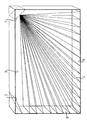
- FIG. 1 An optoelectronic monitoring system according to FIG present invention purely by way of example with reference to the accompanying drawings explained.
- FIG. 1 An optoelectronic monitoring system according to the present invention in a preferred Embodiment shown spatially.
- the drawing shows a room area 3 to be monitored, in the Ceiling area installed a lighting device 1 and an imaging device 2 are.
- the imager is in the Ceiling area arranged opposite the lighting device 1.
- the Lighting device 1 and the imager 2 can, however, also in a different position to each other.
- the lighting device 1 generates light pulses that are to be monitored Room area 3 are emitted.
- the lighting device 1 can be a Act laser light source, the light beam a few millimeters wide generated.
- the light beams emitted in the pulse mode can preferably by an optical deflection unit (not shown) in particular in two mutually perpendicular planes are deflected so that they cover the area to be monitored 3 in a line.
- an optical deflection unit not shown
- the lighting is such that the monitoring area 3 completely filled as possible and on the Floor 5 and the side walls 6 of the monitoring room area 3 straight, lines parallel to each other are projected.
- the lighting device 1 can also be set to be another any two-dimensional projection image generated or only a certain one Solid angle range within the room to be monitored 3 illuminated. In the case shown, the area to be monitored is 3 free, so that the beam of rays freely on the floor 5 and the side wall 6 of the monitoring room area 3 is projected.
- the light pulses emitted into the room area 3 to be monitored are to be monitored from the bottom 5 and the side walls 6 of the Space area 3 or reflected from objects located therein and from Imager 2 detects one of a number arranged in one area Pixels resolved image captured.
- a time measurement unit determines the transit time of the light pulses from the emission the lighting device 1 until it is received by the imaging device 2 for at least one pixel.
- the term is each Light pulse from transmission to reception for every pixel determined in order to have a runtime profile of the whole to be monitored To get room area 3.
- a suitable memory not shown
- the time measuring unit determines the transit time of the light pulses from the Transmission by the lighting device 1 until reception by the imager 2 for at least one pixel and compares them currently determined light transit times with the stored reference values. If the time measuring unit deviations between the currently determined Times of light and the stored reference values, the optoelectronic monitoring system can provide a corresponding Output monitoring signal.
- the reference values of the light propagation times can also be determined if the existing in the area to be monitored 3 Objects assume a given position. If the currently determined Light transit times differ from reference values determined in this way, this is an indication that the one to be monitored Space area 3 located objects changed their predetermined position have, and the optoelectronic monitoring system gives a corresponding Monitoring signal off.
- the principle of operation of the optoelectronic monitoring system according to the invention also allows the lighting device 1 and the imager 2 in the same direction on the one to be monitored Area are aligned. According to a preferred embodiment can therefore the lighting device 1 and the imaging device 2 together be housed in a housing. That way there are none Connection lines between the lighting device 1 and the imaging device 2 required.
- the space requirement of the invention Surveillance system is reduced and installation is simplified, while the reliability of checking one to be monitored Area is improved.
Landscapes
- Engineering & Computer Science (AREA)
- Physics & Mathematics (AREA)
- General Physics & Mathematics (AREA)
- General Life Sciences & Earth Sciences (AREA)
- Geophysics (AREA)
- Multimedia (AREA)
- Theoretical Computer Science (AREA)
- Electromagnetism (AREA)
- Computer Vision & Pattern Recognition (AREA)
- Artificial Intelligence (AREA)
- Life Sciences & Earth Sciences (AREA)
- Remote Sensing (AREA)
- Radar, Positioning & Navigation (AREA)
- Computer Networks & Wireless Communication (AREA)
- Closed-Circuit Television Systems (AREA)
- Burglar Alarm Systems (AREA)
- Radar Systems Or Details Thereof (AREA)
- Studio Devices (AREA)
Applications Claiming Priority (2)
| Application Number | Priority Date | Filing Date | Title |
|---|---|---|---|
| DE29911391U DE29911391U1 (de) | 1999-06-30 | 1999-06-30 | Optoelektronisches Überwachungssystem |
| DE29911391U | 1999-06-30 |
Publications (3)
| Publication Number | Publication Date |
|---|---|
| EP1065522A2 true EP1065522A2 (fr) | 2001-01-03 |
| EP1065522A3 EP1065522A3 (fr) | 2001-03-07 |
| EP1065522B1 EP1065522B1 (fr) | 2005-04-06 |
Family
ID=8075495
Family Applications (1)
| Application Number | Title | Priority Date | Filing Date |
|---|---|---|---|
| EP00113254A Expired - Lifetime EP1065522B1 (fr) | 1999-06-30 | 2000-06-21 | Système de surveillance optoélectronique |
Country Status (3)
| Country | Link |
|---|---|
| EP (1) | EP1065522B1 (fr) |
| AT (1) | ATE292806T1 (fr) |
| DE (2) | DE29911391U1 (fr) |
Cited By (4)
| Publication number | Priority date | Publication date | Assignee | Title |
|---|---|---|---|---|
| EP1548351A2 (fr) | 2003-12-23 | 2005-06-29 | Leuze lumiflex GmbH + Co. KG | Dispositif de surveillance d'une zone de couverture près d'une machine |
| WO2007079883A2 (fr) | 2005-12-22 | 2007-07-19 | Pilz Gmbh & Co. Kg | Procede permettant la configuration d'un dispositif de surveillance destine a la surveillance d'une zone spatiale |
| EP1959271A1 (fr) * | 2007-02-14 | 2008-08-20 | Sick Ag | Agencement de capteur optoélectrique et procédé de vérification du mode de fonctionnement et/ou de l'ajustement d'un agencement de capteur optoélectronique |
| DE102005028490C5 (de) * | 2005-06-20 | 2016-07-14 | Sick Ag | Kamerasystem |
Families Citing this family (2)
| Publication number | Priority date | Publication date | Assignee | Title |
|---|---|---|---|---|
| DE10134305B4 (de) * | 2000-07-18 | 2007-01-11 | Leuze Electronic Gmbh & Co Kg | Optoelektronische Vorrichtung |
| DE102005056265A1 (de) | 2005-11-14 | 2007-05-16 | Pilz Gmbh & Co Kg | Vorrichtung und Verfahren zum Überwachen eines Raumbereichs, insbesondere zum Absichern eines Gefahrenbereichs einer automatisiert arbeitenden Anlage |
Family Cites Families (16)
| Publication number | Priority date | Publication date | Assignee | Title |
|---|---|---|---|---|
| US4915498A (en) * | 1988-04-19 | 1990-04-10 | Malek Joseph H | Range imaging sensor |
| DE3915627A1 (de) * | 1989-05-12 | 1990-11-15 | Dornier Luftfahrt | Optisches radar |
| DE3942770A1 (de) * | 1989-12-23 | 1991-07-11 | Dornier Luftfahrt | Entfernungsbildkamera |
| DE4119797C2 (de) | 1991-06-15 | 1994-02-24 | Leuze Electronic Gmbh & Co | Einen Sender, einen Empfänger und eine Schaltungsanordnung zur Signalauswertung aufweisende Überwachungseinrichtung |
| DE4233810C2 (de) | 1992-10-07 | 2000-02-03 | Sick Ag | Überwachungsvorrichtung bei Arbeitsmaschinen |
| JPH07225276A (ja) | 1994-02-10 | 1995-08-22 | Mitsubishi Electric Corp | 車両用光レーダ装置 |
| DE4422497C2 (de) | 1994-06-28 | 1996-06-05 | Leuze Electronic Gmbh & Co | Vorrichtung und Verfahren zum optoelektronischen Erfassen von Gegenständen |
| DE4422886C2 (de) | 1994-06-30 | 1997-02-20 | Daimler Benz Aerospace Ag | Verfahren und Einrichtung zur optischen Bestimmung räumlicher Positionen einzelner reflektierender Objekte |
| US5682229A (en) * | 1995-04-14 | 1997-10-28 | Schwartz Electro-Optics, Inc. | Laser range camera |
| DE19523843C1 (de) | 1995-06-30 | 1997-01-02 | Leuze Electronic Gmbh & Co | Verfahren zum Erfassen von Objekten in einem Überwachungsbereich und Vorrichtung zur Durchführung des Verfahrens |
| DE19601661C1 (de) | 1996-01-18 | 1997-07-17 | Leuze Electronic Gmbh & Co | Verfahren zum Erfassen von Objekten in einem Überwachungsbereich |
| DE29607075U1 (de) | 1996-04-18 | 1996-07-04 | Erwin Sick Gmbh Optik-Elektronik, 79183 Waldkirch | Lumineszenztaster |
| US5889582A (en) * | 1997-03-10 | 1999-03-30 | Virtek Vision Corporation | Image-directed active range finding system |
| DE19730341A1 (de) | 1997-07-15 | 1999-01-21 | Sick Ag | Verfahren zum Betrieb einer opto-elektronischen Sensoranordnung |
| DE59804862D1 (de) * | 1997-09-15 | 2002-08-29 | Rms Kleine Gmbh Vertrieb Elekt | Verfahren und Vorrichtung zur optischen Überwachung eines Raumbereichs |
| DE19757595C2 (de) * | 1997-12-23 | 2000-05-11 | Siemens Ag | Verfahren und Vorrichtung zur Aufnahme eines dreidimensionalen Abstandsbildes |
-
1999
- 1999-06-30 DE DE29911391U patent/DE29911391U1/de not_active Expired - Lifetime
-
2000
- 2000-06-21 DE DE50009961T patent/DE50009961D1/de not_active Expired - Lifetime
- 2000-06-21 AT AT00113254T patent/ATE292806T1/de not_active IP Right Cessation
- 2000-06-21 EP EP00113254A patent/EP1065522B1/fr not_active Expired - Lifetime
Cited By (6)
| Publication number | Priority date | Publication date | Assignee | Title |
|---|---|---|---|---|
| EP1548351A2 (fr) | 2003-12-23 | 2005-06-29 | Leuze lumiflex GmbH + Co. KG | Dispositif de surveillance d'une zone de couverture près d'une machine |
| EP1548351A3 (fr) * | 2003-12-23 | 2006-04-19 | Leuze lumiflex GmbH + Co. KG | Dispositif de surveillance d'une zone de couverture près d'une machine |
| US7412861B2 (en) | 2003-12-23 | 2008-08-19 | Leuze Lumiflex Gmbh & Co., Ltd. | Device for monitoring an area of coverage on a work tool |
| DE102005028490C5 (de) * | 2005-06-20 | 2016-07-14 | Sick Ag | Kamerasystem |
| WO2007079883A2 (fr) | 2005-12-22 | 2007-07-19 | Pilz Gmbh & Co. Kg | Procede permettant la configuration d'un dispositif de surveillance destine a la surveillance d'une zone spatiale |
| EP1959271A1 (fr) * | 2007-02-14 | 2008-08-20 | Sick Ag | Agencement de capteur optoélectrique et procédé de vérification du mode de fonctionnement et/ou de l'ajustement d'un agencement de capteur optoélectronique |
Also Published As
| Publication number | Publication date |
|---|---|
| EP1065522B1 (fr) | 2005-04-06 |
| ATE292806T1 (de) | 2005-04-15 |
| DE29911391U1 (de) | 1999-10-14 |
| EP1065522A3 (fr) | 2001-03-07 |
| DE50009961D1 (de) | 2005-05-12 |
Similar Documents
| Publication | Publication Date | Title |
|---|---|---|
| EP1300691B1 (fr) | Procédé de surveillance et capteur opto-électronique | |
| EP1040366B1 (fr) | Procede et dispositif pour la prise d'une vue tridimensionnelle permettant la mesure d'une distance | |
| DE69305765T2 (de) | System zur Messung des Abstandes zwischen Fahrzeugen | |
| EP1722191B1 (fr) | Détermination de distance | |
| WO2000055642A1 (fr) | Systeme de mesure de distance a resolution locale | |
| EP1794619B1 (fr) | Dispositif de surveillance optique de zones tridimensionnelles | |
| EP0902402B1 (fr) | Procédé et appareil pour la surveillance optique d'un espace | |
| WO2001013029A1 (fr) | Dispositif pour proteger une zone dangereuse, notamment une zone dangereuse d'une machine fonctionnant de maniere automatisee | |
| DE10026710A1 (de) | Optoelektronische Schutzeinrichtung | |
| DE102005012118A1 (de) | Bewegbare Absperrungseinrichtung mit einem Hindernisdetektor | |
| EP0892280A2 (fr) | Procédé pour faire fonctionner un dispositif capteur opto-électronique | |
| DE19735414A1 (de) | Gerät zum Messen des Abstands zwischen Fahrzeugen | |
| EP0253017B1 (fr) | Système et méthode d'arpentage | |
| EP1355128A1 (fr) | Alignement automatique d'un senseur | |
| DE29911390U1 (de) | Optoelektronisches Überwachungssystem | |
| EP3862780B1 (fr) | Balayeur laser de sécurité et procédé de surveillance de vitre frontale | |
| EP3891532A1 (fr) | Système lidar et véhicule à moteur | |
| DE10033608A1 (de) | Verfahren und Vorrichtung zum Absichern eines Gefahrenbereichs, insbesondere des Gefahrenbereichs einer automatisiert arbeitenden Maschine | |
| DE2312588C3 (de) | Aufnahmekopf fur einen optischen Korrelations-Geschwindigkeitsmesser | |
| EP1065522B1 (fr) | Système de surveillance optoélectronique | |
| DE102010043723B4 (de) | Lichtlaufzeitkamerasystem | |
| EP1857838B1 (fr) | Dispositif de protection optoélectrique | |
| DE19718390A1 (de) | Opto-elektronischer Sensor | |
| DE3919917A1 (de) | Optischer sensor fuer die identifizierung eines koerpers | |
| EP2013642A1 (fr) | Procede et dispositif de prise de vue a distance |
Legal Events
| Date | Code | Title | Description |
|---|---|---|---|
| PUAI | Public reference made under article 153(3) epc to a published international application that has entered the european phase |
Free format text: ORIGINAL CODE: 0009012 |
|
| AK | Designated contracting states |
Kind code of ref document: A2 Designated state(s): AT BE CH CY DE DK ES FI FR GB GR IE IT LI LU MC NL PT SE |
|
| AX | Request for extension of the european patent |
Free format text: AL;LT;LV;MK;RO;SI |
|
| PUAL | Search report despatched |
Free format text: ORIGINAL CODE: 0009013 |
|
| AK | Designated contracting states |
Kind code of ref document: A3 Designated state(s): AT BE CH CY DE DK ES FI FR GB GR IE IT LI LU MC NL PT SE |
|
| AX | Request for extension of the european patent |
Free format text: AL;LT;LV;MK;RO;SI |
|
| 17P | Request for examination filed |
Effective date: 20010426 |
|
| AKX | Designation fees paid |
Free format text: AT BE CH CY DE DK ES FI FR GB GR IE IT LI LU MC NL PT SE |
|
| 17Q | First examination report despatched |
Effective date: 20040527 |
|
| GRAP | Despatch of communication of intention to grant a patent |
Free format text: ORIGINAL CODE: EPIDOSNIGR1 |
|
| GRAS | Grant fee paid |
Free format text: ORIGINAL CODE: EPIDOSNIGR3 |
|
| GRAA | (expected) grant |
Free format text: ORIGINAL CODE: 0009210 |
|
| AK | Designated contracting states |
Kind code of ref document: B1 Designated state(s): AT BE CH CY DE DK ES FI FR GB GR IE IT LI LU MC NL PT SE |
|
| PG25 | Lapsed in a contracting state [announced via postgrant information from national office to epo] |
Ref country code: IE Free format text: LAPSE BECAUSE OF FAILURE TO SUBMIT A TRANSLATION OF THE DESCRIPTION OR TO PAY THE FEE WITHIN THE PRESCRIBED TIME-LIMIT Effective date: 20050406 Ref country code: NL Free format text: LAPSE BECAUSE OF FAILURE TO SUBMIT A TRANSLATION OF THE DESCRIPTION OR TO PAY THE FEE WITHIN THE PRESCRIBED TIME-LIMIT Effective date: 20050406 Ref country code: FI Free format text: LAPSE BECAUSE OF FAILURE TO SUBMIT A TRANSLATION OF THE DESCRIPTION OR TO PAY THE FEE WITHIN THE PRESCRIBED TIME-LIMIT Effective date: 20050406 |
|
| REG | Reference to a national code |
Ref country code: GB Ref legal event code: FG4D Free format text: NOT ENGLISH |
|
| REG | Reference to a national code |
Ref country code: CH Ref legal event code: EP |
|
| REG | Reference to a national code |
Ref country code: IE Ref legal event code: FG4D Free format text: LANGUAGE OF EP DOCUMENT: GERMAN |
|
| REF | Corresponds to: |
Ref document number: 50009961 Country of ref document: DE Date of ref document: 20050512 Kind code of ref document: P |
|
| PG25 | Lapsed in a contracting state [announced via postgrant information from national office to epo] |
Ref country code: LU Free format text: LAPSE BECAUSE OF NON-PAYMENT OF DUE FEES Effective date: 20050621 Ref country code: CY Free format text: LAPSE BECAUSE OF FAILURE TO SUBMIT A TRANSLATION OF THE DESCRIPTION OR TO PAY THE FEE WITHIN THE PRESCRIBED TIME-LIMIT Effective date: 20050621 Ref country code: AT Free format text: LAPSE BECAUSE OF NON-PAYMENT OF DUE FEES Effective date: 20050621 |
|
| GBT | Gb: translation of ep patent filed (gb section 77(6)(a)/1977) |
Effective date: 20050608 |
|
| PG25 | Lapsed in a contracting state [announced via postgrant information from national office to epo] |
Ref country code: BE Free format text: LAPSE BECAUSE OF NON-PAYMENT OF DUE FEES Effective date: 20050630 Ref country code: MC Free format text: LAPSE BECAUSE OF NON-PAYMENT OF DUE FEES Effective date: 20050630 |
|
| PG25 | Lapsed in a contracting state [announced via postgrant information from national office to epo] |
Ref country code: DK Free format text: LAPSE BECAUSE OF FAILURE TO SUBMIT A TRANSLATION OF THE DESCRIPTION OR TO PAY THE FEE WITHIN THE PRESCRIBED TIME-LIMIT Effective date: 20050706 Ref country code: SE Free format text: LAPSE BECAUSE OF FAILURE TO SUBMIT A TRANSLATION OF THE DESCRIPTION OR TO PAY THE FEE WITHIN THE PRESCRIBED TIME-LIMIT Effective date: 20050706 Ref country code: GR Free format text: LAPSE BECAUSE OF FAILURE TO SUBMIT A TRANSLATION OF THE DESCRIPTION OR TO PAY THE FEE WITHIN THE PRESCRIBED TIME-LIMIT Effective date: 20050706 |
|
| PG25 | Lapsed in a contracting state [announced via postgrant information from national office to epo] |
Ref country code: ES Free format text: LAPSE BECAUSE OF FAILURE TO SUBMIT A TRANSLATION OF THE DESCRIPTION OR TO PAY THE FEE WITHIN THE PRESCRIBED TIME-LIMIT Effective date: 20050717 |
|
| PG25 | Lapsed in a contracting state [announced via postgrant information from national office to epo] |
Ref country code: PT Free format text: LAPSE BECAUSE OF FAILURE TO SUBMIT A TRANSLATION OF THE DESCRIPTION OR TO PAY THE FEE WITHIN THE PRESCRIBED TIME-LIMIT Effective date: 20050908 |
|
| NLV1 | Nl: lapsed or annulled due to failure to fulfill the requirements of art. 29p and 29m of the patents act | ||
| REG | Reference to a national code |
Ref country code: IE Ref legal event code: FD4D |
|
| PLBE | No opposition filed within time limit |
Free format text: ORIGINAL CODE: 0009261 |
|
| STAA | Information on the status of an ep patent application or granted ep patent |
Free format text: STATUS: NO OPPOSITION FILED WITHIN TIME LIMIT |
|
| ET | Fr: translation filed | ||
| 26N | No opposition filed |
Effective date: 20060110 |
|
| BERE | Be: lapsed |
Owner name: SICK A.G. Effective date: 20050630 |
|
| PGFP | Annual fee paid to national office [announced via postgrant information from national office to epo] |
Ref country code: FR Payment date: 20100706 Year of fee payment: 11 |
|
| PGFP | Annual fee paid to national office [announced via postgrant information from national office to epo] |
Ref country code: CH Payment date: 20100624 Year of fee payment: 11 |
|
| PGFP | Annual fee paid to national office [announced via postgrant information from national office to epo] |
Ref country code: GB Payment date: 20100401 Year of fee payment: 11 |
|
| PGFP | Annual fee paid to national office [announced via postgrant information from national office to epo] |
Ref country code: IT Payment date: 20110627 Year of fee payment: 12 |
|
| REG | Reference to a national code |
Ref country code: CH Ref legal event code: PL |
|
| GBPC | Gb: european patent ceased through non-payment of renewal fee |
Effective date: 20110621 |
|
| REG | Reference to a national code |
Ref country code: FR Ref legal event code: ST Effective date: 20120229 |
|
| PG25 | Lapsed in a contracting state [announced via postgrant information from national office to epo] |
Ref country code: CH Free format text: LAPSE BECAUSE OF NON-PAYMENT OF DUE FEES Effective date: 20110630 Ref country code: LI Free format text: LAPSE BECAUSE OF NON-PAYMENT OF DUE FEES Effective date: 20110630 Ref country code: FR Free format text: LAPSE BECAUSE OF NON-PAYMENT OF DUE FEES Effective date: 20110630 |
|
| PG25 | Lapsed in a contracting state [announced via postgrant information from national office to epo] |
Ref country code: GB Free format text: LAPSE BECAUSE OF NON-PAYMENT OF DUE FEES Effective date: 20110621 |
|
| PG25 | Lapsed in a contracting state [announced via postgrant information from national office to epo] |
Ref country code: IT Free format text: LAPSE BECAUSE OF NON-PAYMENT OF DUE FEES Effective date: 20120621 |
|
| PGFP | Annual fee paid to national office [announced via postgrant information from national office to epo] |
Ref country code: DE Payment date: 20170621 Year of fee payment: 18 |
|
| REG | Reference to a national code |
Ref country code: DE Ref legal event code: R119 Ref document number: 50009961 Country of ref document: DE |
|
| PG25 | Lapsed in a contracting state [announced via postgrant information from national office to epo] |
Ref country code: DE Free format text: LAPSE BECAUSE OF NON-PAYMENT OF DUE FEES Effective date: 20190101 |