EP1065527A2 - Procédé et appareil pour la lecture d'images de radiation - Google Patents
Procédé et appareil pour la lecture d'images de radiation Download PDFInfo
- Publication number
- EP1065527A2 EP1065527A2 EP00202113A EP00202113A EP1065527A2 EP 1065527 A2 EP1065527 A2 EP 1065527A2 EP 00202113 A EP00202113 A EP 00202113A EP 00202113 A EP00202113 A EP 00202113A EP 1065527 A2 EP1065527 A2 EP 1065527A2
- Authority
- EP
- European Patent Office
- Prior art keywords
- phosphor
- group
- phosphor screen
- csx
- eux
- Prior art date
- Legal status (The legal status is an assumption and is not a legal conclusion. Google has not performed a legal analysis and makes no representation as to the accuracy of the status listed.)
- Withdrawn
Links
Images


Classifications
-
- C—CHEMISTRY; METALLURGY
- C09—DYES; PAINTS; POLISHES; NATURAL RESINS; ADHESIVES; COMPOSITIONS NOT OTHERWISE PROVIDED FOR; APPLICATIONS OF MATERIALS NOT OTHERWISE PROVIDED FOR
- C09K—MATERIALS FOR MISCELLANEOUS APPLICATIONS, NOT PROVIDED FOR ELSEWHERE
- C09K11/00—Luminescent materials, e.g. electroluminescent or chemiluminescent
- C09K11/08—Luminescent materials, e.g. electroluminescent or chemiluminescent containing inorganic luminescent materials
- C09K11/77—Luminescent materials, e.g. electroluminescent or chemiluminescent containing inorganic luminescent materials containing rare earth metals
- C09K11/7728—Luminescent materials, e.g. electroluminescent or chemiluminescent containing inorganic luminescent materials containing rare earth metals containing europium
- C09K11/7732—Halogenides
- C09K11/7733—Halogenides with alkali or alkaline earth metals
-
- A—HUMAN NECESSITIES
- A61—MEDICAL OR VETERINARY SCIENCE; HYGIENE
- A61B—DIAGNOSIS; SURGERY; IDENTIFICATION
- A61B6/00—Apparatus or devices for radiation diagnosis; Apparatus or devices for radiation diagnosis combined with radiation therapy equipment
- A61B6/42—Arrangements for detecting radiation specially adapted for radiation diagnosis
- A61B6/4208—Arrangements for detecting radiation specially adapted for radiation diagnosis characterised by using a particular type of detector
- A61B6/4216—Arrangements for detecting radiation specially adapted for radiation diagnosis characterised by using a particular type of detector using storage phosphor screens
-
- A—HUMAN NECESSITIES
- A61—MEDICAL OR VETERINARY SCIENCE; HYGIENE
- A61B—DIAGNOSIS; SURGERY; IDENTIFICATION
- A61B6/00—Apparatus or devices for radiation diagnosis; Apparatus or devices for radiation diagnosis combined with radiation therapy equipment
- A61B6/50—Apparatus or devices for radiation diagnosis; Apparatus or devices for radiation diagnosis combined with radiation therapy equipment specially adapted for specific body parts; specially adapted for specific clinical applications
- A61B6/502—Apparatus or devices for radiation diagnosis; Apparatus or devices for radiation diagnosis combined with radiation therapy equipment specially adapted for specific body parts; specially adapted for specific clinical applications for diagnosis of breast, i.e. mammography
-
- G—PHYSICS
- G01—MEASURING; TESTING
- G01T—MEASUREMENT OF NUCLEAR OR X-RADIATION
- G01T1/00—Measuring X-radiation, gamma radiation, corpuscular radiation, or cosmic radiation
- G01T1/16—Measuring radiation intensity
- G01T1/20—Measuring radiation intensity with scintillation detectors
- G01T1/2012—Measuring radiation intensity with scintillation detectors using stimulable phosphors, e.g. stimulable phosphor sheets
-
- G—PHYSICS
- G01—MEASURING; TESTING
- G01T—MEASUREMENT OF NUCLEAR OR X-RADIATION
- G01T1/00—Measuring X-radiation, gamma radiation, corpuscular radiation, or cosmic radiation
- G01T1/16—Measuring radiation intensity
- G01T1/20—Measuring radiation intensity with scintillation detectors
- G01T1/2012—Measuring radiation intensity with scintillation detectors using stimulable phosphors, e.g. stimulable phosphor sheets
- G01T1/2014—Reading out of stimulable sheets, e.g. latent image
-
- G—PHYSICS
- G01—MEASURING; TESTING
- G01T—MEASUREMENT OF NUCLEAR OR X-RADIATION
- G01T1/00—Measuring X-radiation, gamma radiation, corpuscular radiation, or cosmic radiation
- G01T1/16—Measuring radiation intensity
- G01T1/20—Measuring radiation intensity with scintillation detectors
- G01T1/2012—Measuring radiation intensity with scintillation detectors using stimulable phosphors, e.g. stimulable phosphor sheets
- G01T1/2016—Erasing of stimulable sheets, e.g. with light, heat or the like
-
- G—PHYSICS
- G21—NUCLEAR PHYSICS; NUCLEAR ENGINEERING
- G21K—HANDLING OF PARTICLES OR IONISING RADIATION NOT OTHERWISE PROVIDED FOR; IRRADIATION DEVICES; GAMMA RAY OR X-RAY MICROSCOPES
- G21K4/00—Conversion screens for the conversion of the spatial distribution of X-rays or particle radiation into visible images, e.g. fluoroscopic screens
Definitions
- the present invention relates to a method and a system of reading a radiation image that has been stored in a photostimulable phosphor screen. More particularly the invention relates to the reuse of the photostimulable phosphor screen.
- Radiation image recording systems wherein a radiation image is recorded on a photostimulable phosphor screen by exposing said screen to image-wise modulated penetrating radiation are widely used nowadays.
- the recorded image is reproduced by stimulating the exposed photostimulable phosphor screen by means of stimulating radiation and by detecting the light that is emitted by the phosphor screen upon stimulation and converting the detected light into an electrical signal representation of the radiation image.
- the stimulable phosphor screen can be used in many imaging cycles.
- the reuse of the stimulable phosphor screen is possible when the previously stored radiation image is erased to a sufficient extent.
- the signal of the first image must be reduced by more than a factor of 300.
- the phosphor can be reduced to neutral state by actions like a uniform illumination, irradiation or heating.
- the phosphor screen is erased by illumination with visible light.
- Incandescent lamps are commonly used because they are cheap, high power light sources.
- High power lamps generate a lot of heat, which may destabilise the scanner to read out the storage phosphor screens.
- the size of the read out apparatus has to be rather large in order to enable removal of the heat generated by a powerful erasure unit which is required in order to have a high throughput.
- an erasing light source assembly refers to either a single light source or a group of more than one erasing light source. In the latter case the electrical power which is specified is the electrical power of the total assembly.
- the wavelength of the erasing light source(s) is within the range of 300 nm to 1500 nm.
- a wavelength range from 500 nm to 800 nm is preferred because a divalent europium activated cesium halide phosphor is most efficiently erased with light within this wavelength range.
- Another aspect of the present invention relates to a radiation image read out apparatus for reading a radiation image that has been stored in photostimulable phosphor screen having a surface area not greater than S max , having
- Still another aspect relates to a re-usable radiation detector comprising
- the objects of the present invention are realised in a read out method and apparatus and detector according to the present invention by using a phosphor with a very good erasibility combined with an erasure unit with low electrical power.
- an erasing light source of a low power type is adequate in a system wherein a radiation image is temporarily stored in a divalent europium activated cesium halide phosphor without there being any need for the phosphor screen to remain for an extended period of time in the erasing unit. Consequentially the fact that a low power erasing light source is used has no negative influence on the throughput of the system.
- radioradiation has to be understood as any penetrating radiation and includes irradiation originating from a radioisotope (e.g. Co60, Ir192, Se75, etc.), radiation created by an X-ray generator of any type, radiation and high energy particles created by a high energy radiation generator (e.g. Betatron), radiation from a sample labeled with a radioisotope as is the case in e.g. autoradiography.
- a radioisotope e.g. Co60, Ir192, Se75, etc.
- X-ray generator e.g.
- high energy particles created by a high energy radiation generator e.g. Betatron
- a radiation image read out device (1) according to the present invention is schematically shown in figure 1.
- the device generally comprises a image read out unit (2) and an erasure unit (3).
- the read out and erasure units can be implemented as separate units or can be incorporated into a single unit.
- a first embodiment of an image read out unit is of the flying spot scanner type, this embodiment is shown in greater detail in figure 2.
- the read out unit comprises a source of stimulating radiation (5), more particulary a HeNe laser emitting light at 633 nm.
- the unit further comprises an oscillating mirror for deflecting light emitted by the stimulating laser source onto the photostimulable phosphor screen (7) into the scan direction, a light guide (8) for guiding light emitted by the photostimulable phosphor screen upon stimulation onto a photomultiplier (9).
- the read out unit further comprises means for transporting (not shown) the photostimulable phosphor screen into the sub-scan direction indicated by arrow (10).
- the HeNe laser can be replaced by a diode laser emitting at 630 nm
- the oscillating mirror can be replaced by a multi-facet mirror etc.
- a read out unit of the flying spot type is generally combined with an erasure unit that is optically separated from the read out unit so that there is no interference between read out and erasure.
- the photostimulable phosphor screen is transported through the read unit into the erasure unit.
- An image line which has been read out is subsequently erased.
- the erasure can be performed by a part-by-part (e.g. line-by-line) erasing illumination of the screen or by means of an overall erasing illumination.
- a read out apparatus of the above-described kind is commonly used for read out of phosphor screens of a variety of dimensions which are selected for different kinds of applications.
- the dimensions of the read out apparatus and the available possibilities for adjustment of optical and mechanical components imply a maximum format of the screen that can be read out in an apparatus. This maximum format is denoted as S max .
- the erasure section comprises at least one erasing light source emitting in the range of 300 to 1500 nm.
- the total electrical power of the erasing unit is not more than 1 Joule multiplied by S max wherein S max is the surface of the largest photostimulable phosphor screen that can be read out in the envisioned read out apparatus (in cm 2 ).
- the wavelength range is selected so as to be optimally matched to the characteristics of the europium activated cesium halide phosphor.
- the europium activated cesium halide phosphor is most efficiently erased with erasure light within the wavelength range of 500 to 800 nm.
- an elongate flash lamp such as a Xenon or Krypton flash lamp, is preferably used.
- This kind of flash lamps emits in the range of 500 to 800 nm, and is thus appropiate for erasure of the europium activated cesium halide phosphor. Furthermore it is a low power light source and it has an appropriate shape for integration in a compact read out unit.
- a second embodiment of a read out unit, referred to as scan-head type read out unit type is shown in figure 3.
- the described scan-head type differs from the conventional flying spot type in that in the scan-head type the image read out is line-wise whereas in the conventional flying spot type read out unit the reading is performed in a point-by-point fashion.
- the read out unit comprises a linear light source (15) for emitting stimulating light onto the photostimulable phospor screen.
- This linear light source comprises 4096 individual laser diodes arranged in a row. This light source provides simultaneous illumination of all pixels of a single line of the photostimulable phosphor screen.
- the read out unit further comprises a fiber optic plate (16) for directing light emitted by the phosphor screen upon stimulation onto a linear array of sensor elements (17), more particulary charge coupled devices.
- the fiber optic plate (16) comprises a number of parallel mounted light guiding fibers arranged so as to guide the light emitted by each individual element of an illuminated line onto a sensor element.
- the fiber optic plate can be replaced by an arrangement of selfoc lenses or microlenses.
- a light guide member might even be avoided.
- linear light source can be replaced by a 'flying spot' light source.
- the light emitted by this light source is then deflected by a rotatable polygon mirror onto a scan line on the phosphor screen. In this way one point of this line at the time is illuminated.
- the linear light source is arranged on one side of the phosphor screen, the fiber optic plate and the linear array of sensor elements being arranged on the opposite side. Either of these elements extends in the direction of a scan line.
- the phosphor screen on the one hand and the assembly of fiber optic plate and sensor array on the other hand are displaced relative to eachother in the direction of arrow (18).
- the array of stimulating light sources, the fiber optic plate and the sensor array are arranged at the same side of the photostimulable phosphor screen.
- the photostimulable phosphor screen After read out the photostimulable phosphor screen is erased so that the energy remaining in the screen after read out is released and so that the screen is in a condition for re-use.
- the erasure unit preferably forms part of the read out unit.
- the erasing light source is part of an assembly comprising the stimulating light source,the light guiding and light detecting means.
- the position of the stimulating light source and of the erasing light source is shown schematically in figure 4.
- the erasing section comprises an erasing light source emitting in the range of 300 nm to 1500 nm and having an electrical power of not more than 1 J x S max .
- an elongate flash lamp such as a Xenon or Krypton flash lamp, is preferably used.
- This kind of flash lamps emits in the range of 500 to 800 nm, and is thus appropiate for erasure of the europium activated cesium halide phosphor. Furthermore it is a low power light source which has an appropriate shape for integration in a compact read out unit.
- the erasing light source is arranged parallel to the linear array of stimulating light sources.
- the erasing light source is transported past the image that is read at the same transportation speed in between 30mm/sec and 250 mm/sec. In this way the erasing light source illuminates a line of the image after it has been submitted to read out.
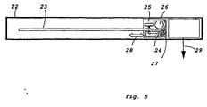
- Another aspect of the present invention relates to a re-usable radiation detector. This type of detector is shown in figure 5.
- the detector comprises an enclosure (22).
- a photostimulable phosphor screen (23) is positioned within the enclosure.
- This screen preferably comprises a divalent cesium halide phoshor, wherein said halide is at least one of chloride and bromide.
- the enclosure further comprises a source of stimulating light (24) arranged for stimulating said phosphor screen and an array of transducer elements (25) for capturing light emitted by the phoshor upon stimulation and for converting said light into an electrical signal representation.
- a source of stimulating light is a linear light source and the array of transducer elements is also a linear array. This embodiment can be made very compact and provides fast read out.
- the enclosure further comprises a linear erasing light source (26) arranged substantially parallel to the stimulating light source.
- the enclosure still further comprises means (not shown) for transporting the assembly (27) of stimulating light source, erasing light source and array of transducer elements relative to the phosphor screen in a so-called sub-scan direction, indicated by arrow (28).
- Means (29) are further provided for communicating the electrical signal representation output by the array of transducer elements to an external signal processing device.
- the phosphor screen remains inside the enclosure during irradiation, read out and erasure.
- the stimulating light source and the array of transducer elements are arranged on opposite sides of the phosphor screen.
- these items may be arranged on the same side of the phosphor screen.
- the stimulable phosphor screen in the several embodiments of the present invention comprises a divalent europium activated cesium halide phosphor.
- a divalent europium activated cesium halide phosphor is known in the art and has for example been disclosed in EP-A-174 875 (and US 5,028,509).
- the phosphor is especially well suited for manufacturing 'binderless' phosphor screens. Binderless phosphor screens provide optimal sharpness.
- a phosphor that has been obtained as a result of the above method of preparation has an increased conversion efficiency compared to the state of the art divalent europium activated cesium halide phosphor.
- the phosphor can be stimulated by means of a lower amount of stimulation energy.
- a photostimulable phosphor screen using such a phosphor is preferably obtained by the method of
- This method of preparation is advantageous because it allows to deposit the phosphor in the form of needle-shaped crystals.
- These needle-shaped phosphor crystals act as light guides so that they reduce the lateral spreading of light in the phosphor layer. Reduced lateral light spread leads to images of higher resolution.
- a phosphor screen containing a CsX:Eu stimulable phosphor, wherein X represents a halide selected from the group consisting of Br and Cl can also be manufactured by performing the steps of :
- This method of preparation is advantageous because it likewise allows to deposit the phosphor in the form of needle-shaped crystals.
- These needle-shaped phosphor crystals act as light guides so that they reduce the lateral spreading of light in the phosphor layer. Reduced lateral light spread leads to images of higher resolution.
- the CsBr:Eu screen was produced in the following way:
- a CsBr:Eu sample screen was made via thermal vapour deposition of CsBr and the EuOBr.
- CsBr was mixed with EuOBr and placed in a container in a vacuum deposition chamber.
- the phosphor was deposited on a glass disk with a thickness of 1.5 mm and a diameter of 40 mm. The distance between the container and the substrate was 10 cm. During evaporation, the substrate was rotated at 12 rpm.
- the substrate temperature was ca. 200°C at the start of the evaporation process.
- the container was heated to a temperature of 750° C.
- the chamber was evacuated to a pressure of 4.10 -5 mbar.
- Ar was introduced in the chamber and the Ar gas pressure was 1.6 10 -2 mbar.
- the resulting screen had a thickness of 850 m.
- the Eu-concentration in the evaporated screen was measured with X-ray fluorescence.
- the phosphor contained 400 ppm of Eu and at the surface side 800 ppm.
- both screens were homogeneously irradiated with a dose of ca. 50 mR at 80 kVp.
- the screens were read out in a flying spot scanner.
- the scanning light source was a 30 mW diode laser emitting at 690 nm.
- a 4 mm Hoya BG-39 (trade name) filter was used to separate the stimulation light from the light emiited by the phosphor screen.
- the scan-average levels (SAL) were determined as the average signal produced by the screens in the photomultiplier tube. The results of this measurement was a SAL1 value for the CsBr:Eu2+ screen and a SAL1 value for the MD-10 screen (Table 1).
- the MD-10 screen was homogeneously irradiated with a dose of ca. 44 R, also at 80 kVp.
- the screen was erased with a 500 W (electrical power) quartz-halogen lamp for 1 s.
- the light intensity at the screen position was measured using a photometer and was 12 mW/cm 2 .
- the CsBr:Eu2+ screen was homogeneously irradiated with a dose of Ca. 166 R, also at 80 kVp.
- the screen was erased with the 500 Watt quartz-halogen lamp for 1 s.
- the light intensity on the screen was, again, 12 mW/cm 2 .
- Ed SAL3 x 50 / (SAL1 x 166,000) where the factor 50 / 166,000 corrects for the difference in dose in the measurements 1 and 3.
- the object of the present invention can be accomplished by making an imaging system based on CsBr:Eu instead of BaFBr:Eu.
- the CsBr:Eu 2+ screen was homogeneously irradiated with a dose of ca. 185 R, also at 80 kVp.
- the screen was erased with the 500 Watt quartz-halogen lamp for 2 s.
- the light intensity on the screen was, again, 12 mW/cm 2 .
- Ed SAL4 x 50 / (SAL1 x 185,000), where the factor 50 / 185,000 corrects for the difference in dose in the measurements 1 and 4.
- Measurement 4 demonstrates that the required erasure depth can be achieved by erasing CsBr:Eu 2+ with an optical power of 12 mW/cm 2 in 2 s, which is equivalent to using an optical energy of 24 mJ/cm 2 .
- a read out system is commonly designed for read out of phosphor screens having a variety of dimensions.
- the largest screens that are used in medical radiography have a size of 35 x 43 cm 2 , i.e. a size of 1,500 cm 2 .
- an erasure depth of 3.10 -5 is reached when the CsBr:Eu2+ screen is erased with an optical energy of 24 mJ/cm 2 .
- Incandescent lamps that are commonly used in erasure units, because they are available at high power, have an efficiency of Ca. 5% in the transformation of electrical energy to light energy [Sristava, AM, TJ Sommerer: Fluorescent Lamp Phosphors, The Electrochemical Society Interface, Summer 1998, p.28].
- optical erasure energy corresponds to an electrical erasure energy of 480 mJ/cm 2 .
- a read out apparatus that allows to erase a phophor screen in 1 s is still a high throughput system and requires an erasure unit with an electrical power of S max x 500 mJ, where S max is the surface area of the largest phosphor screen to be read in the read out apparatus.
- Fluorescent lamps have an efficiency of about 40% in the transformation of electrical energy to light. [Sristava: AM, TJ Sommerer: Fluorescent Lamp Phosphors, The Electrochemical Society Interface, Summer 1998, p.28]. This implies that the calculated optical erasure energy corresponds to an electrical erasure energy of 60 mJ / cm 2 .
- Erasure of the phosphor screen should therefore preferably be possible within 2 minutes or 120 seconds.
- a read out apparatus that allows to erase the storage phoshor screen in 120 seconds and having high efficiency lamps to erase, requires an erasure unit with an electrical power of S max x 0.5 mJ, where S max is the surface area of the largest phosphor screen to be read out in the readout apparatus.
- the scanner requires an erasure unit with high efficiency lamps having an electrical power of S max x 1 mJ, where S max is the surface area of the largesst phosphor screen to be read out in the read out apparatus.
- the erasure unit then requires an electrical power of S max x 2mJ, where S max is the area of the largest phosphor screen to be read out in the readout apparatus.
Landscapes
- Health & Medical Sciences (AREA)
- Life Sciences & Earth Sciences (AREA)
- Engineering & Computer Science (AREA)
- High Energy & Nuclear Physics (AREA)
- Physics & Mathematics (AREA)
- Molecular Biology (AREA)
- Medical Informatics (AREA)
- Chemical & Material Sciences (AREA)
- Spectroscopy & Molecular Physics (AREA)
- General Physics & Mathematics (AREA)
- Optics & Photonics (AREA)
- Pathology (AREA)
- Heart & Thoracic Surgery (AREA)
- Radiology & Medical Imaging (AREA)
- Surgery (AREA)
- Animal Behavior & Ethology (AREA)
- General Health & Medical Sciences (AREA)
- Public Health (AREA)
- Veterinary Medicine (AREA)
- Biophysics (AREA)
- Nuclear Medicine, Radiotherapy & Molecular Imaging (AREA)
- Biomedical Technology (AREA)
- Oral & Maxillofacial Surgery (AREA)
- Dentistry (AREA)
- General Engineering & Computer Science (AREA)
- Inorganic Chemistry (AREA)
- Materials Engineering (AREA)
- Organic Chemistry (AREA)
- Conversion Of X-Rays Into Visible Images (AREA)
- Radiography Using Non-Light Waves (AREA)
- Image Input (AREA)
- Facsimile Scanning Arrangements (AREA)
- Luminescent Compositions (AREA)
- Light Receiving Elements (AREA)
Applications Claiming Priority (5)
| Application Number | Priority Date | Filing Date | Title |
|---|---|---|---|
| US14227699P | 1999-07-02 | 1999-07-02 | |
| US142276P | 1999-07-02 | ||
| US15900499P | 1999-10-08 | 1999-10-08 | |
| US159004P | 1999-10-08 | ||
| US09/595,183 US6504169B1 (en) | 1999-07-02 | 2000-06-16 | Method for reading a radiation image that has been stored in a photostimulable screen |
Publications (2)
| Publication Number | Publication Date |
|---|---|
| EP1065527A2 true EP1065527A2 (fr) | 2001-01-03 |
| EP1065527A3 EP1065527A3 (fr) | 2006-04-05 |
Family
ID=27385785
Family Applications (2)
| Application Number | Title | Priority Date | Filing Date |
|---|---|---|---|
| EP00202110A Withdrawn EP1065524A3 (fr) | 1999-07-02 | 2000-06-13 | Procédé et dispositif pour la reproduction d'images de rayonnement |
| EP00202113A Withdrawn EP1065527A3 (fr) | 1999-07-02 | 2000-06-13 | Procédé et appareil pour la lecture d'images de radiation |
Family Applications Before (1)
| Application Number | Title | Priority Date | Filing Date |
|---|---|---|---|
| EP00202110A Withdrawn EP1065524A3 (fr) | 1999-07-02 | 2000-06-13 | Procédé et dispositif pour la reproduction d'images de rayonnement |
Country Status (3)
| Country | Link |
|---|---|
| US (2) | US6512240B1 (fr) |
| EP (2) | EP1065524A3 (fr) |
| JP (2) | JP2001074895A (fr) |
Cited By (4)
| Publication number | Priority date | Publication date | Assignee | Title |
|---|---|---|---|---|
| US6800870B2 (en) | 2000-12-20 | 2004-10-05 | Michel Sayag | Light stimulating and collecting methods and apparatus for storage-phosphor image plates |
| EP1489626A3 (fr) * | 2003-05-19 | 2006-03-29 | Fuji Photo Film Co., Ltd. | Ecran pour l'enregistrement d'une image obtenue par rayonnement |
| EP1707990A2 (fr) | 2005-03-17 | 2006-10-04 | E2V Technologies (UK) Limited | Capteur à rayons X |
| CN103160277A (zh) * | 2012-09-11 | 2013-06-19 | 佛山安亿纳米材料有限公司 | 双功能转光剂及其制备方法 |
Families Citing this family (20)
| Publication number | Priority date | Publication date | Assignee | Title |
|---|---|---|---|---|
| DE60044254D1 (de) | 1999-07-02 | 2010-06-02 | Agfa Healthcare Nv | Verfahren zur herstellung von einem csx photostimulierbaren phosphor und phosphor-schirmen damit |
| EP1103846B1 (fr) * | 1999-11-23 | 2004-09-15 | Agfa-Gevaert | Panneau à stockage phosphoreux avec un rendement lumineux amélioré |
| US20010007352A1 (en) * | 1999-12-27 | 2001-07-12 | Erich Hell | Binderless storage phosphor screen with needle shaped crystals |
| US20010019115A1 (en) * | 2000-03-01 | 2001-09-06 | Kenji Tajima | Radiation image information reading apparatus |
| US6967339B2 (en) * | 2002-03-26 | 2005-11-22 | Agfa-Gevaert | Needle-shaped cylindrical storage phosphor crystals |
| DE10235051B4 (de) * | 2002-07-31 | 2004-06-09 | Siemens Ag | Verfahren zur Bedampfung eines Trägers mit einem Röntgenleuchtstoff |
| JP2004163895A (ja) * | 2002-09-25 | 2004-06-10 | Fuji Photo Film Co Ltd | 放射線像読取装置および励起光カットフィルタ |
| US20040081750A1 (en) * | 2002-10-25 | 2004-04-29 | Agfa-Gevaert | Storage phosphor screen and preparation method |
| KR100505682B1 (ko) * | 2003-04-03 | 2005-08-03 | 삼성전자주식회사 | 금속-절연체-금속 커패시터를 포함하는 이중 다마신 배선구조 및 그 제조방법 |
| US7057200B2 (en) * | 2003-07-24 | 2006-06-06 | Eastman Kodak Company | Storage phosphor erase |
| US7075100B2 (en) * | 2003-09-22 | 2006-07-11 | Honeywell International Inc. | Confocal scanner system and method |
| EP1526552B1 (fr) * | 2003-10-24 | 2011-09-28 | Agfa HealthCare NV | Système de lecture d'une pluralité des écrans d'enregistrement luminescent différents |
| DE502004012256D1 (de) * | 2004-05-21 | 2011-04-14 | Agfa Gevaert Healthcare Gmbh | Speicherleuchtstoffplatte zur Speicherung von Röntgeninformation |
| US7186996B2 (en) * | 2004-08-06 | 2007-03-06 | Agfa-Gevaert | System for reading out storage phosphor screens |
| JP2006098796A (ja) * | 2004-09-29 | 2006-04-13 | Fuji Photo Film Co Ltd | 放射線画像読取方法 |
| JP2007010805A (ja) | 2005-06-28 | 2007-01-18 | Fujifilm Holdings Corp | 放射線像変換パネルからの放射線エネルギーの放出除去方法 |
| DE602006010367D1 (de) * | 2006-08-10 | 2009-12-24 | Agfa Healthcare Nv | Verfahren zum Löschen von Speicherleuchtstoffträgern |
| JP6179362B2 (ja) * | 2013-11-14 | 2017-08-16 | コニカミノルタ株式会社 | ブライトバーンの消去方法およびブライトバーン消去機能を有する放射線画像撮影装置 |
| US10168288B2 (en) * | 2015-09-21 | 2019-01-01 | General Electric Company | System for radiography imaging and method of operating such system |
| CN108277457B (zh) * | 2017-12-27 | 2020-07-28 | 上海超导科技股份有限公司 | 适用于脉冲激光镀膜的光路装置及其脉冲激光镀膜装置 |
Family Cites Families (12)
| Publication number | Priority date | Publication date | Assignee | Title |
|---|---|---|---|---|
| US3859527A (en) | 1973-01-02 | 1975-01-07 | Eastman Kodak Co | Apparatus and method for producing images corresponding to patterns of high energy radiation |
| JPS59181335A (ja) * | 1983-03-31 | 1984-10-15 | Fuji Photo Film Co Ltd | オ−トラジオグラフイ−における信号検出方法 |
| JPS60121439A (ja) * | 1983-12-05 | 1985-06-28 | Fuji Photo Film Co Ltd | 放射線画像情報読取装置 |
| US5028509A (en) * | 1984-09-14 | 1991-07-02 | Konica Corporation | Method for converting radiographic image, radiation energy storage panel having stimulable phosphor-containing layer and alkali halide phosphor |
| EP0174875B1 (fr) | 1984-09-14 | 1990-06-06 | Konica Corporation | Méthode de conversion d'une image radiographique et écran pour l'enregistrement d'énergie par rayonnement comportant une couche de matière luminescente excitable |
| US4835386A (en) * | 1985-10-18 | 1989-05-30 | Fuji Photo Film Co., Ltd. | Radiation image recording and read-out apparatus |
| US5012095A (en) * | 1987-01-14 | 1991-04-30 | Fuji Photo Film Co., Ltd. | Radiation image recording and read-out apparatus |
| EP0276698B1 (fr) * | 1987-01-16 | 1992-04-22 | Fuji Photo Film Co., Ltd. | Dispositif pour l'enregistrement et la reproduction d'images de rayonnement |
| JPH07109483B2 (ja) * | 1988-09-06 | 1995-11-22 | 富士写真フイルム株式会社 | 蓄積性蛍光体シートのノイズ消去方法 |
| US5072119A (en) * | 1990-04-18 | 1991-12-10 | Fuji Photo Film Co., Ltd. | Radiation image read-out apparatus and erasing apparatus |
| DE69213948T2 (de) * | 1992-11-25 | 1997-04-03 | Agfa Gevaert Nv | Verfahren zur Wiedergabe eines Strahlungsbildes |
| DE69409235T2 (de) * | 1994-09-29 | 1998-10-15 | Agfa Gevaert Nv | Vorrichtung zum Auslesen eines Speicherphosphor-Aufzeichnungsträgers |
-
2000
- 2000-06-13 EP EP00202110A patent/EP1065524A3/fr not_active Withdrawn
- 2000-06-13 EP EP00202113A patent/EP1065527A3/fr not_active Withdrawn
- 2000-06-16 US US09/595,487 patent/US6512240B1/en not_active Expired - Fee Related
- 2000-06-16 US US09/595,183 patent/US6504169B1/en not_active Expired - Fee Related
- 2000-06-29 JP JP2000197098A patent/JP2001074895A/ja active Pending
- 2000-06-29 JP JP2000195725A patent/JP2001074898A/ja active Pending
Non-Patent Citations (1)
| Title |
|---|
| None * |
Cited By (8)
| Publication number | Priority date | Publication date | Assignee | Title |
|---|---|---|---|---|
| US6800870B2 (en) | 2000-12-20 | 2004-10-05 | Michel Sayag | Light stimulating and collecting methods and apparatus for storage-phosphor image plates |
| US7589341B2 (en) | 2000-12-20 | 2009-09-15 | Michel Sayag | Light stimulating and collecting methods and apparatus for storage-phosphor image plates |
| US7825394B2 (en) | 2000-12-20 | 2010-11-02 | Michel Sayag | Light stimulating and collecting methods and apparatus for storage-phosphor image plates |
| EP1489626A3 (fr) * | 2003-05-19 | 2006-03-29 | Fuji Photo Film Co., Ltd. | Ecran pour l'enregistrement d'une image obtenue par rayonnement |
| EP1707990A2 (fr) | 2005-03-17 | 2006-10-04 | E2V Technologies (UK) Limited | Capteur à rayons X |
| US7211817B2 (en) | 2005-03-17 | 2007-05-01 | E2V Technologies (Uk) Limited | X-ray sensor |
| CN103160277A (zh) * | 2012-09-11 | 2013-06-19 | 佛山安亿纳米材料有限公司 | 双功能转光剂及其制备方法 |
| CN103160277B (zh) * | 2012-09-11 | 2015-08-19 | 佛山安亿纳米材料有限公司 | 双功能转光剂及其制备方法 |
Also Published As
| Publication number | Publication date |
|---|---|
| JP2001074898A (ja) | 2001-03-23 |
| JP2001074895A (ja) | 2001-03-23 |
| EP1065524A2 (fr) | 2001-01-03 |
| US6504169B1 (en) | 2003-01-07 |
| US6512240B1 (en) | 2003-01-28 |
| EP1065524A3 (fr) | 2006-04-05 |
| EP1065527A3 (fr) | 2006-04-05 |
Similar Documents
| Publication | Publication Date | Title |
|---|---|---|
| US6504169B1 (en) | Method for reading a radiation image that has been stored in a photostimulable screen | |
| US6528812B1 (en) | Radiation image read-out method and apparatus | |
| EP1065528A2 (fr) | Procédé et appareil pour la lecture d'images de radiation | |
| JP2004528587A (ja) | 記憶蛍光体イメージプレートのための光励起および集積方法および装置 | |
| US20110001052A1 (en) | Computed radiography system | |
| EP0586744A1 (fr) | Méthode pour effacer l'énergie emmagasinée dans un moyen photostimulable au phosphore | |
| US6507039B2 (en) | Apparatus for reading information recorded in a memory layer and an X-ray cassette and X-ray table for use with the apparatus | |
| US5432354A (en) | Radiographic image reading apparatus | |
| US6479835B1 (en) | Radiation image detector | |
| US7211817B2 (en) | X-ray sensor | |
| EP1887385B1 (fr) | Procédé d'effacement de panneaux de stockage phosphorescents | |
| US20080035839A1 (en) | Radiation Image read-out method | |
| US7442952B2 (en) | Method for erasing radiation energy remaining in radiation image storage panel | |
| JP2521452B2 (ja) | 放射線画像読取装置 | |
| JP2670605B2 (ja) | 放射線画像撮影読取装置 | |
| JP2879138B2 (ja) | 放射線画像情報の読取方法 | |
| JPS6397939A (ja) | 放射線像変換パネルの残存放射線像の消去装置 | |
| JP2873834B2 (ja) | 放射線画像情報記録読取装置 | |
| JPH03107941A (ja) | 放射線画像読取装置 | |
| JPH03144557A (ja) | 蓄積性蛍光体のエネルギー消去方法 | |
| JPS63121834A (ja) | 放射線画像情報読取装置 | |
| JPH0389337A (ja) | 放射線画像情報記録読取装置 | |
| JPH05113614A (ja) | 放射線情報記録読取方法および装置 | |
| JP2002116514A (ja) | 蓄積性蛍光体シート、放射線画像情報読取方法および装置 | |
| JP2003186129A (ja) | 放射線画像形成装置 |
Legal Events
| Date | Code | Title | Description |
|---|---|---|---|
| PUAI | Public reference made under article 153(3) epc to a published international application that has entered the european phase |
Free format text: ORIGINAL CODE: 0009012 |
|
| AK | Designated contracting states |
Kind code of ref document: A2 Designated state(s): AT BE CH CY DE DK ES FI FR GB GR IE IT LI LU MC NL PT SE |
|
| AX | Request for extension of the european patent |
Free format text: AL;LT;LV;MK;RO;SI |
|
| RAP1 | Party data changed (applicant data changed or rights of an application transferred) |
Owner name: AGFA-GEVAERT |
|
| PUAL | Search report despatched |
Free format text: ORIGINAL CODE: 0009013 |
|
| AK | Designated contracting states |
Kind code of ref document: A3 Designated state(s): AT BE CH CY DE DK ES FI FR GB GR IE IT LI LU MC NL PT SE |
|
| AX | Request for extension of the european patent |
Extension state: AL LT LV MK RO SI |
|
| 17P | Request for examination filed |
Effective date: 20061005 |
|
| AKX | Designation fees paid |
Designated state(s): DE FR GB |
|
| 17Q | First examination report despatched |
Effective date: 20070108 |
|
| RAP1 | Party data changed (applicant data changed or rights of an application transferred) |
Owner name: AGFA HEALTHCARE NV |
|
| STAA | Information on the status of an ep patent application or granted ep patent |
Free format text: STATUS: THE APPLICATION IS DEEMED TO BE WITHDRAWN |
|
| 18D | Application deemed to be withdrawn |
Effective date: 20070719 |