EP1065541A1 - Connecteur - Google Patents
Connecteur Download PDFInfo
- Publication number
- EP1065541A1 EP1065541A1 EP00112894A EP00112894A EP1065541A1 EP 1065541 A1 EP1065541 A1 EP 1065541A1 EP 00112894 A EP00112894 A EP 00112894A EP 00112894 A EP00112894 A EP 00112894A EP 1065541 A1 EP1065541 A1 EP 1065541A1
- Authority
- EP
- European Patent Office
- Prior art keywords
- connector
- locking
- connector according
- connector part
- ferrule
- Prior art date
- Legal status (The legal status is an assumption and is not a legal conclusion. Google has not performed a legal analysis and makes no representation as to the accuracy of the status listed.)
- Withdrawn
Links
- 230000003287 optical effect Effects 0.000 claims abstract description 10
- 230000000903 blocking effect Effects 0.000 claims description 8
- 230000002093 peripheral effect Effects 0.000 claims description 6
- 239000013307 optical fiber Substances 0.000 abstract description 3
- 230000008878 coupling Effects 0.000 description 17
- 238000010168 coupling process Methods 0.000 description 17
- 238000005859 coupling reaction Methods 0.000 description 17
- 238000004519 manufacturing process Methods 0.000 description 4
- 238000010276 construction Methods 0.000 description 2
- 230000000694 effects Effects 0.000 description 2
- 230000003993 interaction Effects 0.000 description 2
- 230000013011 mating Effects 0.000 description 2
- 238000013459 approach Methods 0.000 description 1
- 230000004323 axial length Effects 0.000 description 1
- 230000005540 biological transmission Effects 0.000 description 1
- 239000002131 composite material Substances 0.000 description 1
- 230000002045 lasting effect Effects 0.000 description 1
- 239000000463 material Substances 0.000 description 1
- 230000005693 optoelectronics Effects 0.000 description 1
Images


Classifications
-
- G—PHYSICS
- G02—OPTICS
- G02B—OPTICAL ELEMENTS, SYSTEMS OR APPARATUS
- G02B6/00—Light guides; Structural details of arrangements comprising light guides and other optical elements, e.g. couplings
- G02B6/24—Coupling light guides
- G02B6/36—Mechanical coupling means
- G02B6/38—Mechanical coupling means having fibre to fibre mating means
- G02B6/3807—Dismountable connectors, i.e. comprising plugs
- G02B6/389—Dismountable connectors, i.e. comprising plugs characterised by the method of fastening connecting plugs and sockets, e.g. screw- or nut-lock, snap-in, bayonet type
- G02B6/3893—Push-pull type, e.g. snap-in, push-on
-
- G—PHYSICS
- G02—OPTICS
- G02B—OPTICAL ELEMENTS, SYSTEMS OR APPARATUS
- G02B6/00—Light guides; Structural details of arrangements comprising light guides and other optical elements, e.g. couplings
- G02B6/24—Coupling light guides
- G02B6/42—Coupling light guides with opto-electronic elements
- G02B6/4292—Coupling light guides with opto-electronic elements the light guide being disconnectable from the opto-electronic element, e.g. mutually self aligning arrangements
-
- G—PHYSICS
- G02—OPTICS
- G02B—OPTICAL ELEMENTS, SYSTEMS OR APPARATUS
- G02B6/00—Light guides; Structural details of arrangements comprising light guides and other optical elements, e.g. couplings
- G02B6/24—Coupling light guides
- G02B6/36—Mechanical coupling means
- G02B6/38—Mechanical coupling means having fibre to fibre mating means
- G02B6/3807—Dismountable connectors, i.e. comprising plugs
- G02B6/381—Dismountable connectors, i.e. comprising plugs of the ferrule type, e.g. fibre ends embedded in ferrules, connecting a pair of fibres
- G02B6/3818—Dismountable connectors, i.e. comprising plugs of the ferrule type, e.g. fibre ends embedded in ferrules, connecting a pair of fibres of a low-reflection-loss type
- G02B6/3821—Dismountable connectors, i.e. comprising plugs of the ferrule type, e.g. fibre ends embedded in ferrules, connecting a pair of fibres of a low-reflection-loss type with axial spring biasing or loading means
-
- G—PHYSICS
- G02—OPTICS
- G02B—OPTICAL ELEMENTS, SYSTEMS OR APPARATUS
- G02B6/00—Light guides; Structural details of arrangements comprising light guides and other optical elements, e.g. couplings
- G02B6/24—Coupling light guides
- G02B6/36—Mechanical coupling means
- G02B6/38—Mechanical coupling means having fibre to fibre mating means
- G02B6/3807—Dismountable connectors, i.e. comprising plugs
- G02B6/381—Dismountable connectors, i.e. comprising plugs of the ferrule type, e.g. fibre ends embedded in ferrules, connecting a pair of fibres
- G02B6/3825—Dismountable connectors, i.e. comprising plugs of the ferrule type, e.g. fibre ends embedded in ferrules, connecting a pair of fibres with an intermediate part, e.g. adapter, receptacle, linking two plugs
-
- G—PHYSICS
- G02—OPTICS
- G02B—OPTICAL ELEMENTS, SYSTEMS OR APPARATUS
- G02B6/00—Light guides; Structural details of arrangements comprising light guides and other optical elements, e.g. couplings
- G02B6/24—Coupling light guides
- G02B6/36—Mechanical coupling means
- G02B6/38—Mechanical coupling means having fibre to fibre mating means
- G02B6/3807—Dismountable connectors, i.e. comprising plugs
- G02B6/3869—Mounting ferrules to connector body, i.e. plugs
Definitions
- the invention relates to a connector with two pluggable and interlocking connector parts, at least one Connector part with at least one connection element, in particular one optical ferrule for light guides, which can be coupled when plugged together Connector parts in a predetermined axial position relative to the other connector part is held.
- Such connectors are found, for example, in the connection of Light guides with other optical or opto-electronic components Use e.g. be used in motor vehicles.
- the ones to be connected In practice, light guides are at one free end with one provided ferrule-like connecting element, which is referred to as a ferrule becomes.
- a ferrule becomes.
- the other connector part e.g. an optical or electro-optical module, arranged, via which light is coupled in and out.
- connection element it is the problem (object) on which the invention is based, one To create connectors of the type mentioned, the mated Connector parts as precise and permanent as possible axial positioning of the connection element relative to the other connector part guaranteed and in particular the connection is as simple as possible to manufacture and to solve again.
- the one connector part is axially fixed coupled connection element when plugging together with the other Lockable connector part and the locking by a relative to the Connector parts axially movable locking element can be secured.
- the axial positioning of the connection element takes place by locking with the other connector part. Because the connector is already axially fixedly coupled to one connector part by locking the connection element with the other connector part also locked the two connector parts together, i.e. it the axial positioning of the connecting element and the locking of the two connector parts. Securing the lock takes place according to the invention by the locking element, being because of the axial Mobility of the locking element relative to the connector parts The purpose of securing no longer need to be moved. Compliance the exact positioning of the connection element and thus compliance is a permissible minimum tolerance range in this way guaranteed. In light guide systems, the invention ensures Connectors in both electro-optical and mechanical Regarding reliable and lasting connections.
- the Locking and securing when plugging the connector parts together automatically.
- the effort required to produce the plug connection reduced to a minimum.
- the locking of the connecting element at in the predetermined axial Position of the connecting element is the one Only then connector part axially coupled connecting element with the other Connector part locks when it is in the desired relative position has obtained this connector part. This makes a particularly exact Positioning of the connection element achieved with minimal tolerances.
- the locking element relative to an axially fixed to the connecting element couplable connector element of the connector part movable.
- the Locking element and the connector element can be inserted into one another according to the invention or be formed one inside the other, and it is according to the invention also possible, the locking element at least in some areas to be arranged inside the connector element.
- the energy stored in this way becomes free as soon as the lock engages with the connection element stands and thereby the blocking of the blocking element is released, which therefore automatically jumps to its end position in which it is Locking secures.
- the Invention in the area of its interacting with the lock In the end, beveled in this way in a blocked and locked by the coil spring To be able to bias engagement with the connecting element.
- Locking sections of the lock in the direction of a peripheral recess of the connection element be charged.
- the locking sections can be made in one piece with the connector element and e.g. provided in the form of locking arms his. It is also possible to use a separate component e.g. in form of curved spring wire to provide for locking.
- the spring wire can, for example, be bent into a U shape and axially in a suitable manner be firmly arranged in the connector part.
- the Outside of the connector part that can be coupled to the connection element partially formed by the locking element.
- the locking element accessible from the outside, so that the plug-in connection is simply through Moving the locking element in the unlocking direction and subsequent Pull apart the two connector parts again can.
- this is with the Interlocking connector part designed as an intermediate piece, which on both sides with a connector part having a connecting element is pluggable.
- the intermediate piece which is a kind of adapter for The two connector parts are used, so-called in-line connections between two connection elements and thus e.g. Light guides made become.
- the intermediate piece which preferably with regard its coupling or plug-in area one with an electro-optical Module provided connector part, can be designed so that it is fully assembled within the two when plugged together each provided with a connector element connector parts is.
- the plug connection is not unnecessarily extended in this way.
- the coupling areas of the intermediate piece are preferably of identical construction, as a result of which only a single design of couplable with connection elements Connector parts is required.
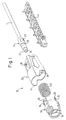
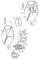
- Fig. 1 shows three components of a connector part 10, which is part of a Connector according to an embodiment of the invention.
- the Connector part 10 comprises a sleeve-like connector element 20, a also sleeve-like locking element 18 of smaller diameter as well a coil spring 22.
- the locking element 18 can from the front into the connector element 20 are inserted, diametrically opposite, operating areas 33 each having an operating trough 34 in the area of corresponding recesses 35 of the connector element 20 arranged and thus accessible from the outside in the assembled state are.
- the connector element 20 is provided with an extension 11, which approximately over half the circumference of the connector element 20 over the front End protrudes beyond, but also as extending over the entire scope sleeve-shaped extension could be formed.
- connection element 10 With the connector part 10 is a connection element in the form of a ferrule 14 connectable, the ferrule-like the free end of one with a sheath 17 provided light guide 16 surrounds.
- the ferrule 14 is in the front Area 27 with a taper and in the middle area with a Provided circumferential recess 26.
- the cylindrical ferrule 14 has the further a rear locking area 29, over which they with can be coupled to the connector element 20.
- 1 is also a half-shell 40 of an optional receiving device for receiving the ferrule 14 and the light guide 16 shown. The cradle can be locked with the connector element 20.
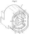
- FIG. 2 shows the other connector part 12 of the connector according to the invention, which can be plugged together with the connector part 10 of FIG. 1.
- An electro-optical module is arranged in the connector part 12 2 cannot be recognized and which interacts with the light guide 16 from FIG. 1, to optical signals to electrical signals or vice versa convert. In principle, this can be any one act electro-optical module. That is the electro-optical module Receiving connector part 12 is also referred to as a header and can be designed either as a plug-in part or as a receiving part.
- the connector part or header 12 includes an inner part 42 and an outer part 44, which are either formed in one piece or releasably together can be connected, for example locked.
- the radial space between inner part 42 and outer part 44 is large enough to Extension 11 of the connector element 20 of the ferrule 14 receiving Connector part 10 of Fig. 1 when the two connector parts 10, 12 are put together.
- each piece with the inner part 42 are two diametrically opposed, each approximately a semicircular cross section having locking portions 24 formed opposite two also diametrically opposite, but a larger one Sections 43 having a distance from one another are rotated by 90 °.
- the sections 43 of the inner part 42 have an arcuate cross section on.
- the two locking sections 24 of the inner part 42 are each with provided a radially outwardly projecting retaining projection 68a, that the projections 68a an approximately perpendicular to the longitudinal axis of the Connector part 12 extending surface in the form of an interrupted annulus form. As will be explained below with reference to FIGS. 3a-3d, serve the projections 68a for blocking the locking element 18 of the connector part 10 of Fig. 1 when plugging the two connector parts together 10, 12.
- the two locking sections are also in the area of their front end 24 with radially inwardly projecting engagement projections 68b provided.
- the engagement projections 68b are in the mated position State of the connector according to the invention with the ferrule 14 at their peripheral recess 26 in engagement and are for this purpose with a trough-shaped, to the cylindrical shape of the ferrule 14 in the area provided their circumferential recess 26 adapted inside.
- the locking sections 24 are elastically deformable in such a way that they pushed radially apart, i.e. can be spread out.
- the distance the locking portions 24 is dimensioned such that the Spreading occurs by inserting the ferrule 14.
- the preferred material for the connector part 12 as well as for the locking element 18 and the connector element 20 of the ferrule 14 receiving Connector part 10 is plastic.
- the engagement sections 68 in particular those projecting radially inwards Engagement projections 68b, can be essentially without resistance slide along the outer surface of the ferrule 14.
- the ferrule 14 is received Connector part 10 held by a user on the connector element 20, with its front end surrounding the tip of the ferrule 14 between Inner part 42 and outer part 44 of the other connector part 12 pushed becomes.
- the electro-optical module 28 which can be seen in FIG. 3a can, for example are inserted laterally into the connector part 12, wherein in the illustrated Embodiment the positioning of the module 28 by a Bracket 32 of the inner part 42 and by a separate and for example resilient positioning piece 30 takes place.
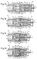
- Fig. 3a it can also be seen that the front end of the locking element 18 is provided with a slope 58a, and that the peripheral recess 26 on the free end of the ferrule 14 facing Side is limited by a slope 60.
- the two connector parts 10, 12 are plugged together so far, that the lying on the outside of the central part of the ferrule 14 Locking sections 24 maximum with respect to the respective ferrule 14 are pressed apart and protrude radially outwards Holding projections 68a block the locking element 18, which with its Sloping 58a in a form-fitting manner in the area of the holding projections 68a Engagement sections 68 abuts.
- FIG. 3c shows the state immediately before the ferrule 14 reaches its predetermined one axial position relative to connector part 12 reached, i.e. right away before the two connector parts are completely plugged together 10, 12. While the connector element 20 together with the axially firmly coupled ferrule 14 pushed further into the connector part 12 was, the locking element 18 has not moved because it the holding projections 68a of the locking portions 24 were blocked. in the State of Fig. 3c, the locking element 18 is still blocked because of the projections 68b are not yet in engagement with the circumferential recess 26. Due to the relative movement between The connector element 20 and locking element 18 becomes the coil spring 22 stretched between the rear end of the connector element 20 and the one that moves backwards relative to the connector element 20 Locking element 18 is compressed.
- the interlock between the interlocking portions 24 and the ferrule 14 can slide due to the sliding over the engagement sections 68 Do not release locking element 18.
- the interlock between ferrule 14 and the connector part receiving the electro-optical module 28 12 is therefore in the finally assembled state according to FIG. 3d secured by the locking element 18. Since the ferrule 14 is axially fixed to the Connector element 20 of the connector part 10 is coupled, ensures the latching between the locking portions 24 and the ferrule 14 at the same time for locking the connector parts 10, 12 together.
- the Securing the axial position of the ferrule 14 by the locking element 18 therefore also forms the locking of the two at the same time Connector parts 10, 12 with each other. Additional locking and securing devices are therefore not necessary according to the invention.
- connectors only require a single plugging movement and both locking and securing take place automatically when plugged together.
- To release the connector it only required the locking element 18 against the force of the coil spring 22 withdraw.
- the projections 68b disengage from the circumferential recess 26 of the ferrule 14, if the connector element 20 and thus the axially coupled with it Ferrule 14 via the locking element 18 from the connector part 12 is pulled out.
- the engagement projections 68b slide along the bevel 60 out of the circumferential recess 26. The two connector parts 10, 12 can thus be completely separated from one another.
- the locking element 18 is withdrawn via the externally accessible ones Operating areas 33 (see. Fig. 1) and is ergonomic shaped actuating troughs 34 facilitated. As can be seen from Fig. 1, can the operating areas 33 with corresponding arrow marks and labels. Likewise, the outside of the connector element 20 with arrow marks and labels be provided, which indicate to a user that to manufacture the connector that receives the ferrule 14 connector part 10 is to be held on the connector element 20.
- the ferrule 14 With the ferrule 14 in the axial end position according to FIG. 3d the light entry and / or exit surface of the light guide 16 in one optimal coupling or decoupling of light ensuring position relative to the respective electro-optical module 28 in the invention Connector positioned.
- This optimal alignment between Light guide 16 and module 28 is through the locking portions 24th and securing them permanently by means of the locking element 18 with minimal Maintain tolerances.
- the connector according to the invention with a so-called CPA (Connecter Position Assurance) function, i.e. the Locking element 18 not only secures the axial position of the ferrule 14 and thus the light guide 16, but also the relative position of the Connector parts 10, 12.
- CPA Connecter Position Assurance
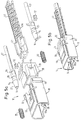
- Fig. 4 shows another embodiment of the invention in which a Connector part 12 'is formed as an intermediate piece, the two identical Has locking areas, as described above in connection with 2 and 3 have been described. Two rotated 180 ° against each other, connector parts 10 each receiving an optical ferrule 14 can be connected in such a way that each Ferrule 14 locked by the respective pair of locking sections 24 and the locking is secured by the respective locking element 18 becomes.
- the intermediate piece 12 'thus serves as an adapter for two identical Connector parts 10.
- the axial length of the adapter 12 ' is dimensioned such that the light entry or Light exit surfaces of the light guide 16 when connector parts are plugged together 10, 12 'at an optimal distance for the transmission of light are positioned to each other. Furthermore, the intermediate piece 12 'executed such that it is complete when the plug connection is made is arranged within the connector parts 10.
- This design of the connector part 12 allows the production of so-called In-line connections using two identical connector parts 10 without unnecessarily increasing the length of the light guide system.
- the connector parts 10, 12, 12 ' can also be used for coupling several ferrules 14 and thus several light guides 16 simultaneously be trained.
- the connector part 12 could, for example several adjacent pairs of locking sections 24 be provided, while the connector parts 10 each lying side by side Areas corresponding to connector element 20 for the ferrule 14 and respective locking elements 18 would have.
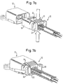
- the connector part 10 which is another embodiment of the invention comprises a locking element 18 and a connector element 20, the interposition of two coil springs 22, the are plugged on pin 54 of the connector element 20, put together and can be locked together.
- the connector element 20 is axially fixed to a coupling piece 50, which on one End of a receiving device 41 for light guide 16 is formed.
- the Receiving device 41 has two receiving channels 41a into which in each case a light guide 16 provided with a sheath 17 is inserted can be.
- an optical one Ferrule 14 is provided, the respective as a ferrule-like connecting element Light guide 16 surrounds.
- the ferrules 14 are in the respective receiving area of the coupling piece 50 fixable.
- the ferrule 14 are each with a Provided circumferential recess 26 in the form of an annular groove from which the ferrule 14 taper towards the tip. 5b shows that in the assembled state of the connector part 10 and when the coupling piece 50 is coupled in, the tapering front areas 27 of the ferrule 14 protrude from the coupling piece 50, however are still within the locking element 18.
- Both the locking element 18 and the connector element 20 are each provided with operating areas 33 and 31, on which the relevant Element for releasing or establishing the plug connection by a user is held, as described in more detail elsewhere.
- the Operating areas 33 of the locking element 18 include laterally protruding Approaches while the operating areas 31 of the connector element 20 each provided as a multi-graded surface area are.
- the connector element 20 In the assembled state of the connector part 10 are the connector element 20, with which the coupling piece 50 of the receiving device 41 - and thus the optical ferrule 14 and the light guide 16 - axially are firmly coupled, and the locking element 18 against each other in the axial direction slidable.
- the connector element 20 by rib-like Elevations 56 performed on the outside of the locking element 18.
- the locking element 18 has two locking sections arranged in the center 58 provided between which are in the assembled state 5b, the ferrule 14 are located. In their front area they are Locking sections 58 are each provided with a bevel 58a.
- the connector part 12 according to FIGS. 6a and 6b, which with the connector part 10th 5a and 5b can be plugged together and to accommodate an electro-optical Module 28 is used, is also referred to as a header.
- connection 28b and coupling areas 28a for light guides electro-optical module 28, for which basically any one Module can be provided, is in an inner part 42 of the connector part 12 inserted and by a positioning piece 30 with resilient, each impinging on a coupling area 28a of the electro-optical module 28 Areas 30a in the desired position in the inner part 42 fixed.
- a spring wire 78 serves as a lock for the ferrule 14, which with the Connector part 10 of Fig. 5a and 5b can be coupled.
- the one shown in Fig. 6a Spatial structure of the spring wire 78 is obtained by a wire is first bent into a narrow U-shape and this U-shape again is bent approximately into a U-shape.
- One leg of the final U will thus from the two parallel free ends of the Spring wire 78 formed which as locking portions 24 of the lock serve.
- Slit-shaped passages 45 are formed in the inner part 42, into which the legs of the U-shaped spring wire 78 can be inserted. From Fig.
- Fig. 7a is indicated by the arrows that for making the connector the ferrule 14 receiving connector part 10 to the of externally accessible actuation areas 31 of the connector element 20 is to be held.
- Fig. 7b is indicated by the arrows - the locking element 18 at its operating areas 33 to take.
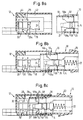
- Fig. 8a are on the connector part 12 of the spring wire 78, which is perpendicular to the drawing plane extending locking sections 24 and the outlines of the electro-optical module 28 and the positioning piece 30 to recognize.
- the are with the locking portions 58 of the locking element 18 provided with the bevels 58a can be seen between which the axially fixed with the not shown Connector element 20 coupled ferrule 14 are arranged. While the tapered front region 27 of the ferrule 14 each over the Locking portions 58 protrudes, is located with the peripheral recess 26 provided area of the ferrule 14 in the axial direction the height of the non-beveled areas of the locking sections 58.
- the two connector parts 10, 12 are already plugged together so far that the ferrule 14 each with their tapered front area 27 between the locking portions 24 protrude into the passages 48 recognizable in FIGS. 6a and 6b.
- the locking sections 24 of the spring wire 78 are at Pushing the ferrule 14 apart through its front region 27 and in the state according to FIG. 8c by the bevels 58a the locking portions 58 pressed onto the ferrule 14.
- the ferrules 14 are axially fixedly coupled to them Connector element 20 has been inserted further into the connector part 12, the ferrule 14 now being in its predetermined final axial positions relative to the connector part 12 and thus to the electro-optical Module 28 are.
- the front ends of the ferrule 14 and thus the light entry and / or light exit surfaces of the respective Light guides 16 are therefore located within the respective coupling area 28a and thus in one for coupling or decoupling Optimal light distance to the electro-optical module 28.
- the Locking sections 24 in the circumferential recesses 26 of the ferrule 14 dodge into it and are over the bevels 58a by the compressed coil springs 22 in the mating direction biased locking element 18 pressed into the circumferential recesses 26.
- the blocking of the blocking sections 58 is released in that so that the energy stored in the coil springs 22 is released and the locking element 18 jerkily forward into the electro-optical Module 28 receiving connector part 12 moves into it.
- the locking sections 24 of the spring wire 78 prevent, on the one hand, that the ferrule 14 is pulled out over the connector element 20 can be. Because the connector element 20 is axially fixed to the ferrules 14 is coupled, but are not only the ferrule 14 with the connector part 12, but also the two connector parts 10, 12 with one another locked. An additional lock between which the ferrule 14 receiving connector part 10 and the header 12 is thus not mandatory.
Landscapes
- Physics & Mathematics (AREA)
- General Physics & Mathematics (AREA)
- Optics & Photonics (AREA)
- Mechanical Coupling Of Light Guides (AREA)
Applications Claiming Priority (2)
| Application Number | Priority Date | Filing Date | Title |
|---|---|---|---|
| DE1999129592 DE19929592A1 (de) | 1999-06-28 | 1999-06-28 | Steckverbinder |
| DE19929592 | 1999-06-28 |
Publications (1)
| Publication Number | Publication Date |
|---|---|
| EP1065541A1 true EP1065541A1 (fr) | 2001-01-03 |
Family
ID=7912833
Family Applications (1)
| Application Number | Title | Priority Date | Filing Date |
|---|---|---|---|
| EP00112894A Withdrawn EP1065541A1 (fr) | 1999-06-28 | 2000-06-19 | Connecteur |
Country Status (2)
| Country | Link |
|---|---|
| EP (1) | EP1065541A1 (fr) |
| DE (1) | DE19929592A1 (fr) |
Cited By (4)
| Publication number | Priority date | Publication date | Assignee | Title |
|---|---|---|---|---|
| WO2006052420A1 (fr) * | 2004-11-10 | 2006-05-18 | Corning Cable Systems Llc | Connecteur à fibre optique installable sur site |
| EP1783524A1 (fr) * | 2005-11-03 | 2007-05-09 | Ridgemount Technologies Limited | Ensemble de connexion pour fibre optique |
| EP2012153A1 (fr) * | 2007-07-06 | 2009-01-07 | Ridgemount Technologies Limited | Assemblée d'embout de fibre optique |
| EP3427346A4 (fr) * | 2016-01-15 | 2020-03-18 | Senko Advanced Components Inc. | Adaptateurs et connecteurs étroits à libération à distance à ressort |
Families Citing this family (1)
| Publication number | Priority date | Publication date | Assignee | Title |
|---|---|---|---|---|
| DE10108285A1 (de) * | 2001-02-21 | 2002-09-12 | Tyco Electronics Amp Gmbh | Steckverbindung |
Citations (5)
| Publication number | Priority date | Publication date | Assignee | Title |
|---|---|---|---|---|
| EP0141958A1 (fr) * | 1983-10-17 | 1985-05-22 | Siemens Nixdorf Informationssysteme Aktiengesellschaft | Dispositif de couplage verrouillable |
| EP0338727A2 (fr) * | 1988-04-19 | 1989-10-25 | AT&T Corp. | Assemblage de connecteur avec un mécanisme de verrouillage |
| EP0510240A1 (fr) * | 1991-04-23 | 1992-10-28 | Interlemo Holding S.A. | Dispositif de connexion |
| EP0571325A1 (fr) * | 1992-05-20 | 1993-11-24 | Diamond S.A. | Fiche pour une fibre optique |
| US5335301A (en) * | 1993-05-05 | 1994-08-02 | Methode Electronics, Inc. | Fiber optic connector with sliding key |
Family Cites Families (4)
| Publication number | Priority date | Publication date | Assignee | Title |
|---|---|---|---|---|
| DE3118489A1 (de) * | 1981-05-09 | 1982-11-25 | Bunker Ramo Corp., 60521 Oak Brook, Ill. | Verbinder fuer lichtwellenleiter |
| US5233674A (en) * | 1991-11-21 | 1993-08-03 | Methode Electronics, Inc. | Fiber optic connector with sliding tab release |
| CH685267A5 (de) * | 1992-11-26 | 1995-05-15 | Diamond Sa | Steckverbindung für Lichtwellenleiter. |
| DE9314172U1 (de) * | 1993-09-20 | 1993-12-16 | Spinner GmbH Elektrotechnische Fabrik, 80335 München | LWL-Stecker mit einer Vorrichtung zum Verrasten mit einer Kupplungshülse |
-
1999
- 1999-06-28 DE DE1999129592 patent/DE19929592A1/de not_active Withdrawn
-
2000
- 2000-06-19 EP EP00112894A patent/EP1065541A1/fr not_active Withdrawn
Patent Citations (5)
| Publication number | Priority date | Publication date | Assignee | Title |
|---|---|---|---|---|
| EP0141958A1 (fr) * | 1983-10-17 | 1985-05-22 | Siemens Nixdorf Informationssysteme Aktiengesellschaft | Dispositif de couplage verrouillable |
| EP0338727A2 (fr) * | 1988-04-19 | 1989-10-25 | AT&T Corp. | Assemblage de connecteur avec un mécanisme de verrouillage |
| EP0510240A1 (fr) * | 1991-04-23 | 1992-10-28 | Interlemo Holding S.A. | Dispositif de connexion |
| EP0571325A1 (fr) * | 1992-05-20 | 1993-11-24 | Diamond S.A. | Fiche pour une fibre optique |
| US5335301A (en) * | 1993-05-05 | 1994-08-02 | Methode Electronics, Inc. | Fiber optic connector with sliding key |
Cited By (8)
| Publication number | Priority date | Publication date | Assignee | Title |
|---|---|---|---|---|
| US7204644B2 (en) | 2004-03-24 | 2007-04-17 | Corning Cable Systems Llc | Field installable optical fiber connector |
| WO2006052420A1 (fr) * | 2004-11-10 | 2006-05-18 | Corning Cable Systems Llc | Connecteur à fibre optique installable sur site |
| JP2008520005A (ja) * | 2004-11-10 | 2008-06-12 | コーニング ケーブル システムズ リミテッド ライアビリティ カンパニー | 現場取付け光ファイバコネクタ |
| CN100485431C (zh) * | 2004-11-10 | 2009-05-06 | 康宁光缆系统有限责任公司 | 可现场安装的光纤连接器 |
| AU2005305200B2 (en) * | 2004-11-10 | 2011-06-09 | Corning Cable Systems Llc | Field installable optical fiber connector |
| EP1783524A1 (fr) * | 2005-11-03 | 2007-05-09 | Ridgemount Technologies Limited | Ensemble de connexion pour fibre optique |
| EP2012153A1 (fr) * | 2007-07-06 | 2009-01-07 | Ridgemount Technologies Limited | Assemblée d'embout de fibre optique |
| EP3427346A4 (fr) * | 2016-01-15 | 2020-03-18 | Senko Advanced Components Inc. | Adaptateurs et connecteurs étroits à libération à distance à ressort |
Also Published As
| Publication number | Publication date |
|---|---|
| DE19929592A1 (de) | 2001-01-04 |
Similar Documents
| Publication | Publication Date | Title |
|---|---|---|
| EP1152497B1 (fr) | Connecteur circulaire | |
| DE69111223T2 (de) | Steckverbinder-Vorrichtung. | |
| DE2332427C2 (de) | Elektrischer Steckverbinder | |
| DE19940489B4 (de) | Steckverbindung | |
| EP1102098B1 (fr) | Connecteur pour fibres optiques | |
| EP0805366A1 (fr) | Connecteur | |
| DE3040803A1 (de) | Steckverbinder fuer lichtwellenleiter | |
| DE9102805U1 (de) | Verbinder mit einer Überverbinderanordnung für ein Paar Lichtleiter-Verbinder | |
| DE1615644C3 (de) | Elektrischer Steckverbinder | |
| DE19652838A1 (de) | Stecker einer elektrischen Steckverbindung und elektrische Steckverbindung | |
| DE3027827A1 (de) | Steckverbinder fuer lichtwellenleiter | |
| CH703904A2 (de) | Steckverbinder. | |
| DE3940230A1 (de) | Steckeranordnung fuer ein mehradriges kabel | |
| DE19855824C2 (de) | Verbindungserkennungsmechanismus für eine Steckverbindung aus einem Stecker und einer Steckbuchse | |
| EP0984524B1 (fr) | Connecteur électrique en deux parties et avec un élément de couplage et un élément mobile de vérfication | |
| DE3200265A1 (de) | Steckverbinder | |
| DE29918358U1 (de) | Kuppler für Koaxialsteckverbinder | |
| DE10221517B4 (de) | Verfahren zum Einführen von Anschlussklemmen bei einer Steckverbindung zur Verhinderung eines unvollständig verbundenen Zustands | |
| EP0599780A1 (fr) | Connecteur pour guide d'onde optique | |
| EP1065541A1 (fr) | Connecteur | |
| DE3232125C2 (fr) | ||
| DE19619374C1 (de) | Steckverbindung | |
| EP0532955A2 (fr) | Fixation par clippage avec moyens de verrouillage pour connecteur coaxial HF | |
| DE2456340A1 (de) | Steckverbinder | |
| DE9320829U1 (de) | Steckverbindung für Lichtwellenleiter |
Legal Events
| Date | Code | Title | Description |
|---|---|---|---|
| PUAI | Public reference made under article 153(3) epc to a published international application that has entered the european phase |
Free format text: ORIGINAL CODE: 0009012 |
|
| AK | Designated contracting states |
Kind code of ref document: A1 Designated state(s): DE ES FR GB IT |
|
| AX | Request for extension of the european patent |
Free format text: AL;LT;LV;MK;RO;SI |
|
| 17P | Request for examination filed |
Effective date: 20010213 |
|
| AKX | Designation fees paid |
Free format text: DE ES FR GB IT |
|
| 17Q | First examination report despatched |
Effective date: 20060703 |
|
| GRAP | Despatch of communication of intention to grant a patent |
Free format text: ORIGINAL CODE: EPIDOSNIGR1 |
|
| RTI1 | Title (correction) |
Free format text: OPTICAL CONNECTOR |
|
| STAA | Information on the status of an ep patent application or granted ep patent |
Free format text: STATUS: THE APPLICATION IS DEEMED TO BE WITHDRAWN |
|
| 18D | Application deemed to be withdrawn |
Effective date: 20071017 |