EP1065815A2 - Protocole de transmission pour la transmission de données sur une sousporteuse d'une émission en modulation de fréquence - Google Patents
Protocole de transmission pour la transmission de données sur une sousporteuse d'une émission en modulation de fréquence Download PDFInfo
- Publication number
- EP1065815A2 EP1065815A2 EP20000305478 EP00305478A EP1065815A2 EP 1065815 A2 EP1065815 A2 EP 1065815A2 EP 20000305478 EP20000305478 EP 20000305478 EP 00305478 A EP00305478 A EP 00305478A EP 1065815 A2 EP1065815 A2 EP 1065815A2
- Authority
- EP
- European Patent Office
- Prior art keywords
- data
- frame
- data groups
- information
- broadcasting
- Prior art date
- Legal status (The legal status is an assumption and is not a legal conclusion. Google has not performed a legal analysis and makes no representation as to the accuracy of the status listed.)
- Withdrawn
Links
- 230000005540 biological transmission Effects 0.000 title description 12
- 238000009432 framing Methods 0.000 claims description 18
- 239000000872 buffer Substances 0.000 claims description 11
- 230000004044 response Effects 0.000 claims description 5
- 238000012544 monitoring process Methods 0.000 claims 1
- 238000004891 communication Methods 0.000 description 22
- 238000010586 diagram Methods 0.000 description 13
- 238000012546 transfer Methods 0.000 description 12
- 238000000034 method Methods 0.000 description 3
- 238000013459 approach Methods 0.000 description 2
- 239000000284 extract Substances 0.000 description 2
- 230000002708 enhancing effect Effects 0.000 description 1
- KSNNEUZOAFRTDS-UHFFFAOYSA-N fominoben Chemical compound ClC=1C=CC=C(NC(=O)C=2C=CC=CC=2)C=1CN(C)CC(=O)N1CCOCC1 KSNNEUZOAFRTDS-UHFFFAOYSA-N 0.000 description 1
- 229960004594 fominoben Drugs 0.000 description 1
- 230000000977 initiatory effect Effects 0.000 description 1
- 230000007246 mechanism Effects 0.000 description 1
- 238000012986 modification Methods 0.000 description 1
- 230000004048 modification Effects 0.000 description 1
- 238000012545 processing Methods 0.000 description 1
- 230000003252 repetitive effect Effects 0.000 description 1
- 230000011664 signaling Effects 0.000 description 1
Images





Classifications
-
- H—ELECTRICITY
- H04—ELECTRIC COMMUNICATION TECHNIQUE
- H04H—BROADCAST COMMUNICATION
- H04H20/00—Arrangements for broadcast or for distribution combined with broadcast
- H04H20/28—Arrangements for simultaneous broadcast of plural pieces of information
- H04H20/33—Arrangements for simultaneous broadcast of plural pieces of information by plural channels
- H04H20/34—Arrangements for simultaneous broadcast of plural pieces of information by plural channels using an out-of-band subcarrier signal
-
- H—ELECTRICITY
- H04—ELECTRIC COMMUNICATION TECHNIQUE
- H04H—BROADCAST COMMUNICATION
- H04H60/00—Arrangements for broadcast applications with a direct linking to broadcast information or broadcast space-time; Broadcast-related systems
- H04H60/02—Arrangements for generating broadcast information; Arrangements for generating broadcast-related information with a direct linking to broadcast information or to broadcast space-time; Arrangements for simultaneous generation of broadcast information and broadcast-related information
- H04H60/07—Arrangements for generating broadcast information; Arrangements for generating broadcast-related information with a direct linking to broadcast information or to broadcast space-time; Arrangements for simultaneous generation of broadcast information and broadcast-related information characterised by processes or methods for the generation
-
- H—ELECTRICITY
- H04—ELECTRIC COMMUNICATION TECHNIQUE
- H04H—BROADCAST COMMUNICATION
- H04H20/00—Arrangements for broadcast or for distribution combined with broadcast
- H04H20/02—Arrangements for relaying broadcast information
- H04H20/06—Arrangements for relaying broadcast information among broadcast stations
-
- H—ELECTRICITY
- H04—ELECTRIC COMMUNICATION TECHNIQUE
- H04H—BROADCAST COMMUNICATION
- H04H2201/00—Aspects of broadcast communication
- H04H2201/10—Aspects of broadcast communication characterised by the type of broadcast system
- H04H2201/13—Aspects of broadcast communication characterised by the type of broadcast system radio data system/radio broadcast data system [RDS/RBDS]
-
- H—ELECTRICITY
- H04—ELECTRIC COMMUNICATION TECHNIQUE
- H04H—BROADCAST COMMUNICATION
- H04H2201/00—Aspects of broadcast communication
- H04H2201/70—Aspects of broadcast communication characterised in that receivers can be addressed
-
- H—ELECTRICITY
- H04—ELECTRIC COMMUNICATION TECHNIQUE
- H04H—BROADCAST COMMUNICATION
- H04H60/00—Arrangements for broadcast applications with a direct linking to broadcast information or broadcast space-time; Broadcast-related systems
- H04H60/09—Arrangements for device control with a direct linkage to broadcast information or to broadcast space-time; Arrangements for control of broadcast-related services
- H04H60/14—Arrangements for conditional access to broadcast information or to broadcast-related services
Definitions
- RBDS Radio Broadcast Data System
- a radio station that utilizes the RBDS standard can broadcast the title and artist of songs that are currently playing on that radio station. Alternatively, the radio station could simply broadcast its call letters.
- a specially configured radio referred to as a "smart radio", or a pager device, is required to view that information.
- Smart radios include hardware circuits or software applications that convert received RBDS signals into the information contained therein.
- the information that is contained within an RBDS signal originates at a terminal such as a laptop computer or a personal digital assistant (PDA).
- a terminal such as a laptop computer or a personal digital assistant (PDA).
- PDA personal digital assistant
- a user inputs the information to a user interface application, running on the laptop computer or PDA, that converts the information to a digital data stream.
- the digital data stream is transmitted to a "communications hub" by means of a modem.
- the communications hub is typically a centrally located computer system.
- the communications hub executes an application that formats the digital data stream according to a signaling protocol that is suitable for transmitting data to an orbiting satellite. Once formatted, the communications hub transmits the digital data stream over a satellite uplink to the orbiting satellite.
- the satellite contains a radio transceiver which decodes and re-modulates the uplink signal for re-transmission over a number of downlink signals. The signal is subsequently transmitted back to earth over those downlink signals and is received by receivers referred to as "terrestrial repeater stations.”
- the terrestrial repeater stations are typically commercial frequency-modulated (FM) radio broadcast stations. Those broadcast stations include hardware referred to as RBDS encoders.
- Each RBDS encoder transmits a signal on a 57 kilohertz subcarrier of the frequency transmitted by the radio broadcast station.
- Each terrestrial repeater station receives a downlink signal from the orbiting satellite and converts it to a frequency modulated signal. The terrestrial repeater station also configures the information contained in that signal according to the RBDS protocol and subsequently broadcasts the FM signal on the 57 kilohertz subcarrier frequency.
- the frequency modulated RBDS signal is transmitted as a bi-phase coded signal having a data rate of 1,187.5 bits per second. That signal is received by the radio receivers or pagers such that the information can be conveyed to the operator of the vehicle or the carrier of the pager.
- the RBDS protocol requires that information received by the receiver units is configured in a group/block structure. That structure is comprised of data groups transmitted at a frequency of approximately 11 groups per second. Each data group is made up of four blocks of information, with each block containing 26 bits. Those 26 bits include a 16 bit data portion and a 10 bit check word, or CRC, portion.
- the RBDS protocol defines several group types that specify different configurations of information sent to a receiver unit. One of those groups, referred to as the RBDS open data application group 12A, specifies that the first two blocks of information must contain formatting information and the second two blocks can contain up to 32 bits of data (i.e. the message generated by the user). Therefore, each message is limited to 32 bits of data per transmission.
- Prior art approaches to transmitting more than 32 bits of information have consisted of broadcasting two different group types in an alternating manner. The transmissions are repeated for a period of time in hopes that the receiver unit will receive and store the data contained in both data groups. Such approaches are not desirable because the amount of data that can be transmitted in this manner is very limited.
- the present invention is applicable to the RBDS protocol, for example, to enhance it so that it is capable of handling framed data thus enabling transmissions of larger amounts of related information to the receiver units. Also repetitive transmission may be avoided so avoiding wasting signal bandwidth.
- the present invention can be used to enhance the RBDS open data application group data format such that framed data can be sent using the RBDS protocol.
- Bit locations within the open data application (ODA) group data signal format may be defined in such a way that information concerning the start, middle and end of a frame of data, and the type of data contained in that frame, are transmitted to a receiver unit.
- Data that comprises the start of a frame of data may be designated as such by bit locations referred to as a frame control field.
- data within the frame is designated as comprising the middle of that frame of data.
- the data that comprises the middle of the frame of data can significantly extend the frame size.
- the frame control bits indicate that the end of the frame of data has been reached.
- an apparatus for passing information between a dispatcher unit and an intelligent transceiver unit.
- the apparatus includes a communications hub unit for receiving information from the dispatcher unit and for determining characteristics of that information such that it can be apportioned into a data frame.
- the communications hub configures the information in a first configuration that includes delimiters for indicating the characteristics of the information.
- the delimiters can be indicative of the data frame's length and type.
- the apparatus may also include a repeater station for receiving the information and delimiters from the communications link.
- the repeater station can include an encoder unit for apportioning the received information into a plurality of data groups that compose the data frame and for configuring those data groups according to a second configuration. That second configuration includes frame control fields for indicating the arrangement of the data groups within the data frame.
- the intelligent transceiver unit includes a receiver unit for receiving the data groups and for grouping them in accordance with the frame control fields, such that said data groups are conveyed to the intelligent transceiver unit in a related manner.
- the frame control fields store values that indicate whether the associated number of data groups comprises a start of said frame, a middle of said frame, or an end of said frame.
- the first configuration is in accordance with the STX/ETX/ESC protocol and the second configuration is in accordance with the ODA group data format as enhanced by the inclusion of the frame control fields.
- the frame control fields are included within a channel field of the ODA group data format.
- FIG. 1 is a pictorial diagram of an embodiment of a communication system according to the present invention.
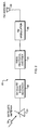
- FIG. 2 is a block diagram of a terrestrial repeater station of the communication system of Fig. 1.
- FIG. 3A is a block diagram of the format of an ODA Beacon that is transmitted from the terrestrial repeater station of Fig. 2.
- FIG. 3B is a block diagram of the format of an RBDS ODA group data signal that is transmitted from the terrestrial repeater station of Fig. 2.
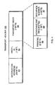
- FIG. 4 is a block diagram of a transport header portion of the RBDS ODA group data format of Fig. 4, according to the present invention.
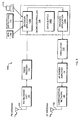
- FIG. 5 is a block diagram of an intelligent transceiver unit according to the present invention.
- FIG. 6 is a block diagram of a receive site that receives information from the intelligent transceiver unit of Fig. 6.
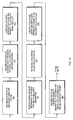
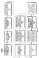
- FIGs. 7A-7C are flow diagrams of a multiple data group transfer via the communication system of Fig.1, according to the present invention.
- the present invention provides a method for enhancing the RBDS protocol such that the beginning, middle and end of frames of related data groups can be identified by receiving units.
- the communication system 10 includes a dispatcher computer system 12 executing a user interface application, a communications hub 14 coupled to the dispatcher computer system 12 by a communications link 16 such as a telephone line or a computer network.
- the communications hub 14 is connected to an orbiting satellite 18 by a satellite uplink signal 19.
- the orbiting satellite is further connected to a number of terrestrial repeater stations 20a-20d by satellite downlink signals 30a-30d.
- Each of the terrestrial repeater stations 20a-20d includes an RBDS encoder 22 for transmitting RDBS configured signals on a 57 kilohertz subcarrier of the frequency broadcast by the associated terrestrial repeater station.
- the FM signals broadcast on that subcarrier are received by a receiver unit 24, such as a radio receiver or pager 24 that can be disposed in a tractor trailer cab. It should be recognized that the receiver unit 24 can be disposed in a number of types of vehicles such as cars, ships, trains and any type of cargo container coupled thereto.
- a message or receiver unit command is input to the user interface running on the dispatcher computer system 12.
- Dispatcher computer system 12 converts the message or command to a digital data stream and sends it over a telephone line or computer network to the communications hub 14.
- Communications hub 14 converts the message into a signal suitable for transmission to satellite 18.
- Orbiting satellite 18 includes a radio transceiver 28 that decodes and re-modulates the uplink signal 18a for transmission on downlink signals 30a-30d. Subsequently, orbiting satellite 18 transmits the reformatted signals to the terrestrial repeater stations 20a-20d. Each terrestrial repeater station 20a-20d receives one of the downlink signals 30a-30d and converts it into a frequency-modulated signal.
- the message or command contained in that FM signal is formatted according to the RBDS protocol, as modified by the present invention, and then broadcast on the above mentioned subcarrier frequency. The modifications allow an entire data frame, comprising one or more data groups, to be broadcast from the terrestrial repeater station 20a-20d.
- the signal transmitted by the terrestrial repeater station 20a-20d is received by all receiver units 24 that are within its transmission range. However, by use of identification bits defined by the embedded network protocol, a single receiver unit 24 can be identified as the recipient. In such a manner, the message or command is conveyed from the dispatcher computer system 12 to a given receiver unit 24.
- the terrestrial repeater station 20 includes a satellite antenna 31, a satellite signal receiver 32, an RBDS protocol encoder 34, an FM modulator 36 and an FM antenna 38 connected in a serial manner.
- a downlink signal 30 is received by satellite antenna 31 and transmitted to satellite signal receiver 32.
- the data that is contained in downlink signal 30 has been formatted by the communications hub 14 using the STX/ETX/ESC protocol and contains additional framing information. In other words, additional frame information precedes the associated message or command and indicates the data type and the length of the frame.
- RBDS protocol encoder 34 periodically issues an open data application beacon 35 to the FM modulator 36 and it is broadcast by FM antenna 38.
- An ODA beacon 35 is a signal that is broadcast to a receiver unit 24 to cause it to responsively listen to the frequency on which the beacon was broadcast. Once the receiver unit 24 is listening to that frequency, a signal that contains message or command data can subsequently be received.
- the ODA beacon 35 is made up of four sixteen-bit blocks of information, each interspersed with a ten-bit check word or CRC code.
- the first block is referred to as the "program identifier" or PI field 40.
- the PI field 40 includes a code that identifies the terrestrial repeater station that transmitted the ODA beacon 35.
- the code contained in PI field 40 may be displayed by radios referred to as "smart radios”.
- the second block 42 includes several fields.
- the first field is referred to as the "group type code” field 44.
- the group type code field 44 includes four bits that define the type of transmission. For example, ODA beacons 35 are identified by a group type code of "0011".
- the second block 42 further includes a program type or PTY code field 46 and an ODA spec field 48 that are each five bits wide.
- the PTY code field 46 is used by smart radios to arrange broadcasts according to particular formats. Accordingly a user can scan broadcasts within a given format so as to more quickly determine a station to be listened to.
- the ODA spec field 48 further includes an "application group type" field 50 and a B0 field 52.
- the application group type field 50 and B0 field 52 include the group type on which to find the application data.
- Block three of the ODA beacon 35 is referred to as the "application data" field 56.
- the application data field 56 includes information regarding the network to which the beacon is being transmitted over.
- selected bits can be set to indicate different configurations. For example, bit 15 is referred to as the "quiet zones apply" bit. That bit indicates whether a list of geographical regions, where transmissions from the receiver unit are not permitted, will be transmitted from the associated terrestrial repeater station 20.
- the "quiet zones apply” bit is set to a logical "1" in the ODA beacon 35, the receiver unit 42 is not allowed to transmit until it receives "quiet zone information" from the terrestrial repeater station.
- Bits 14-11 indicate whether a particular type of receiver unit is supported by the associated terrestrial repeater station 20.
- bits 10 through 2 are reserved for future use and therefore are not utilized.
- bits 1 and 0 designate a reference base year for all dates transmitted from the receiver unit. The two bit value corresponds to a base year to be used by the receiver when reporting date and time information to the dispatcher computer system 12.
- Block four of the ODA beacon 35 is referred to as the "Application ID" field 60.
- the Application ID field 60 identifies this ODA beacon as being associated with a particular broadcast signal, for example the Terion broadcast signal.
- the value of the Application ID field 60 is registered to be unique within the RBDS standard.
- the RBDS protocol encoder 34 conveys an ODA group data signal to the FM modulator 36 which is broadcast by FM antenna 38.
- the ODA group data signal transfers the actual data input to the dispatcher computer system 12 and the frame information which encapsulates that data.
- the ODA group data signal includes a sequence of four blocks of information.
- the first block contains a PI code field 62 that is similar to PI code field 40 of the ODA beacon 35.
- the second block 64 of the ODA group data signal is comprised of a group type code field 66 comprising four bits containing the group type from the Application Group Type field 50 of the ODA beacon 35 and a PTY code field 72 comprising four bits.
- the second block 64 of the ODA group data signal further includes a channel field 74 that comprises 5 bits.
- the channel field 74 is divided into a frame control field 90, comprising two bits, and a frame type field 92, comprising three bits.
- the frame control field 90 indicates whether the data contained in blocks 76 and 78 of the ODA group data signal comprise the start of a frame (SOF), the middle of a frame (MOF), or the end of a frame (EOF). Accordingly, the framing control field is contained in each data group that is sent to the receiver unit 42. Therefore, the receiver unit 42 will be able to concatenate the data contained in the ODA group data signal, beginning with the data identified as the start of the frame and ending with the data identified as the end of the frame.
- the second control of the framing and packetizing of data is the frame type field 92.
- the frame type 92 permits simultaneous reception of data on multiple virtual paths at essentially the same time. Therefore, groups of one type of data could be interspersed with groups of a different type of data and the receiver will store those in different data buffers using the frame type field 92 to distinguish between the two types. Because the frame type field 92 comprises three bits, eight different frame types can be defined. Therefore, groups of data associated with those eight different frame types can be interspersed. The receiver will be able to differentiate between those data types and store them in their own data buffers. For example, being able to intersperse different types of data allows multiple priority and vendor data to be mixed on the same network and ODA group without causing undue queuing or reliance on other data streams.
- Blocks three 76 and four 78 of the ODA group data signal contain the message or command to be conveyed to the receiver unit 24.
- Blocks 76 and 78 each contain 16 bits of information, therefore a total of 32 bits of information can be sent in a single data group. Without the present invention, a single data group of information was all that could be transmitted to a receiver unit 42. Subsequent ODA group data signals could be sent, thereto, but the receiver unit would not identify them as conveying related information. Therefore a 64 bit message could not be transferred to the receiver unit 42 as a single message.
- an embodiment of the present invention layers a framed packet linked protocol on top of the existing RBDS group data format structure. More specifically, the five bits of channel field 74 are used to form two significant controls for the framing of data groups to be transferred to receiver unit 24. In other words, a series of thirty-two-bit groups of data can be transferred to receiver unit 42 in such a way that they will be identified as a single message or command.
- Receiver unit 24 contains a central processing unit (CPU) based micro-controller 106.
- CPU central processing unit
- receiver unit 24 receives an ODA group data signal having a frame control field 90 that indicates that the data contained therein is the start of a frame
- a decoder application 106a running on micro-controller 106 clears a data buffer 106c in which to store the frame data.
- the decoder application 106a will concatenate each additionally received data block, from subsequent ODA group data signals, in the data buffer until an ODA group data signal is received that contains data that represents the end of the data frame.
- data that can be contained in a single data group do not contain a CRC since the RBDS protocol has a 10 bit check word for every 16 bits of data. Those 10 bit check words follow every 16 bits of data in the ODA group data signal, as shown.
- a CRC or checksum will be computed for the data contained within each group based upon the type of data indicated in the frame type field 92. The size of that CRC, and the algorithm used to compute it, is dependant on the frame type.
- the length of a frame is determined to be all of the bytes to be transmitted in blocks three 76 and four 78 of the series of ODA group data signals starting with the ODA group data signal that has a framing control field 90 that indicates it is the start of the frame and ending with an ODA group data signal having a framing control field 90 that indicates that it is the end of the frame. Therefore, the minimum data length of a frame is 32 bits, or a single ODA group data signal. In a preferred embodiment of the invention, the maximum frame length is set to 200 bytes, or fifty ODA group data signals.
- higher layer protocol information such as for a link layer, transport layer, or network layer, may be added to such frames.
- the transport header 100 is disposed in the fourth byte of the concatenated data frame and includes a twenty-four bit destination address 93, a protocol ID comprising one bit, and a transport body comprising 7 bits.
- the protocol ID field 94 contains a value indicative of whether the associated data transfer is included in a multiple number of data groups or in a single data group (i.e., a multiple number of ODA group data signals).
- the protocol ID field 94 of the present embodiment includes a logical zero for a multi group transfer or a logical one for a single group transfer.
- the transport body 104 includes a framing field 96, a sequence number field 97 and an acknowledge request field 98.
- the framing field 96 includes information similar to the framing control field 90 of the ODA group data signal (See Fig. 4). Therefore, framing field 96 includes values that indicate the start of frame, middle of frame or end of frame.
- the sequence number field 97 of transport header 100 comprises 4 bits indicating the relative position of the associated data group within the overall data frame or message. For example, where a multiple data group transfer includes five data groups, each will get a sequential number from one to five. The data group comprising the beginning of the frame will receive sequence number one while the data group comprising the end of the frame will receive sequence number five.
- the acknowledge requested field 110 comprises one bit that indicates whether the receiver unit 42 should reply to the frame with an acknowledge signal indicative of whether it has been received.
- the acknowledgment is formed by sending a message back to the initiating unit that contains the message's sequence number.
- the ITU 24a is configured to receive ODA Beacons 35 and ODA group data signals.
- the ITU 24a includes an FM antenna 100 for receiving those broadcast signals.
- the broadcast signals are conveyed to an FM receiver unit 102 that performs several functions.
- the FM receiver unit 102 scans a range of broadcast frequencies until it detects an ODA Beacon 35. Once the ODA Beacon 35 is detected, the FM receiver unit 102 monitors that frequency until an ODA group data signal is broadcast.
- the FM receiver unit 102 demodulates the ODA group data signal and transfers it to an RBDS decoder unit 104 that extracts the information from the frame control field 90, the frame type field 92 and the data fields 76 and 78.
- That information is conveyed to a micro-controller 106 that has an electrical connection, such as a serial bus connection, to a global positioning system (GPS) 108, an array of detectors 110 and a messaging terminal 112.
- GPS global positioning system
- the detectors 110 provide information regarding, for example, whether the vehicle or container to which it is attached has been opened or whether the ambient temperature has reached a low or a high threshold point.
- the data that is conveyed to the micro-controller 106 either includes a command to initiate acquisition of status information from the GPS 108 or detectors 110, or includes a text message to be displayed on the messaging terminal 112.
- the micro-controller 106 may also receive data to send back to the dispatcher unit 12 in response to the text message displayed on the messaging terminal 112.
- micro-controller 106 Once the micro-controller 106 has performed the requested operation, data to be returned to the dispatcher computer system 12 is conveyed to an encoder application 106b running on micro-controller 106. The data is presented to an oscillator unit 116 that produces a corresponding frequency modulated signal. That frequency modulated signal is conveyed to a high frequency (HF) amplifier 118 and subsequently to a compensation network 120 before it is broadcast on an HF antenna 122.
- HF high frequency
- Receive site 124 includes an array of HF antennas 126.
- the antenna array 126 receives the signal broadcast by HF antenna 122 and conveys it to an HF receiver circuit 128.
- HF receiver circuit 128 conveys the signal to a digital signal processor 130 that is executing a demodulator application.
- the digital signal processor 130 demodulates the signal and transmits the digital data, via phone lines, to the communications hub 14. Subsequently, the communications hub 14 routes that data signal to the dispatcher computer system 12 via phone lines 16.
- a flow diagram depicts the operation of a multiple group transfer originating at the dispatcher computer system 12 and terminating at the ITU 24a.
- ITU 24a is connected to a tractor-trailer and cargo container combination that is at a remote location from the dispatcher computer system 12.
- a text message is input to the dispatcher computer system 12 for the purpose of being displayed on message terminal 112 of ITU 24a (Step 200).
- the text message is transmitted to terrestrial repeater stations 20a-20d (Step 210).
- Satellite antenna 31 receives the re-modulated signal from orbiting satellite 18 and passes it to satellite signal receiver 32 (Step 212). Satellite signal receiver 32 de-modulates the signal, thereby reconstructing the data type and frame length information (Step 214). Subsequently, the digital data that was input to dispatcher computer system 12 is also reconstructed (Step 216). The data type, frame length and data are passed to RBDS protocol encoder 34 such that they can be arranged in the ODA group data format and broadcast as an ODA group data signal (Step 218).
- the RBDS protocol encoder 34 begins to arrange the framed data according to the ODA group data format (Step 220).
- the initial data composes a network header and a transport header 100 to be placed at the head of the frame or message.
- Transport header 100 includes a logical zero in its protocol Id field 94 to indicate that the data will comprise more than thirty-two bits of information and therefore requires the broadcast of multiple groups, each containing a portion of the total amount of data.
- Transport header 100 also includes a transport body 95 having framing field 96, sequence number field 97 and acknowledgment requested field 98. Because the data that is associated with the initial ODA group data signal represents the start of the data frame, the framing field 96 will include a logical "01" (Step 228).
- the sequence number field 97 includes a logical "0001" indicating that the data conveyed in the instant ODA group data signal comprises the first thirty-two bits of the data frame (Step 230). Further, the acknowledge requested field 98 will include a logical "0" indicating that issuance of an acknowledgment message, in response to receipt of the data, is not requested (Step 232).
- the RBDS protocol encoder 34 generates fields 62 and 64 of the ODA group data signal.
- the RBDS protocol encoder 34 generates the second block 64 of the ODA group data signal which includes the group type code field 66, the program type code field 72, the frame control field 90 and the frame type field 92 (Step 234).
- the frame control field 90 includes a logical "10" indicating that the data represents the start of the data frame.
- the frame type field 92 includes a logical "001,” indicating that the data is low priority data (Step 236).
- the first sixteen bits of header data are included in block three 76 of the ODA group data signal and the second sixteen bits included in block four 78. Accordingly, the initial ODA group data signal has been configured (Step 238).
- a CRC or checksum is generated after each block of the ODA group data signal is constructed. The results of that CRC are also included adjacent to the associated block within the ODA group data signal.
- each portion of the first ODA group data signal is conveyed to FM modulator 36.
- the data included in each portion is modulated and then broadcast on FM antenna 38 (Step 240). That signal is received by the ITU 42a via FM antenna 100 and FM receiver 102 (Step 242).
- FM receiver 102 demodulates the signal and passes it to RBDS decoder 104 (Step 244).
- RBDS decoder 104 extracts the network and transport headers and the data from the demodulated ODA group data signal (Step 246).
- the transport header and the data is conveyed to decoder application 106a running on micro-controller 106 (Step 248).
- micro-controller 106 clears a data buffer 106c in which to store the data contained in blocks three 76 and four 78 (Step 250). As will be shown, micro-controller 106 concatenates each additionally received data group that is part of the associated frame, in that data buffer. Such concatenation terminates when an ODA group data signal is received having a frame control field 90 that indicates the end of the data frame has been reached.
- Step 252 generation of the second ODA group data signal is initiated.
- RBDS protocol encoder 34 includes a logical "00" in framing field 96 of transport header 100 and in frame control field 90 to indicate that the associated data constitutes the middle of the data frame (Step 254).
- micro-controller 106 concatenates the data from block three 76 and block four 78 with the data from the first ODA group data signal, in data buffer 106c (Step 256).
- Step 258 when the second ODA group data signal is completely generated by RBDS protocol encoder 34, generation of the third ODA group data signal is initiated (Step 258).
- RBDS protocol encoder 34 includes a logical "10" in framing field 96 and in frame control field 90 to indicate that the associated data constitutes the end of the data frame (Step 260).
- micro-controller 106 concatenates the data from block three 76 and block four 78 with the data from the first and second ODA group data signals (Step 262). Once all of the data associated with the frame is stored in the data buffer, micro-controller 106 transfers that data to message terminal 112 for display (Step 264).
- micro-controller 106 executes multiple layers of software such as the data link layer software and the transport layer software.
- the transport header information is processed by the transport layer software while the remainder of the ODA group data signal is processed by the data link layer software. Accordingly, the framing information is repeated in both the transport header 100 and in frame control field 90.
- the message or command information can be conveyed to the RBDS protocol encoder 34 through a connection to a local computer system rather than via communications hub 14 and orbiting satellite 18.
- a user can enter information to be conveyed to the ITU 42a which is converted into a digital data stream. That digital data stream can be input to RBDS protocol encoder 34 and configured into a data frame of related groups as described above. Subsequently, the configured data frame is broadcast to the ITU 42a.
- RBDS protocol encoder 34 could have circuitry that enables it to receive a digital data stream from a communication medium such as the world wide web. Accordingly, a user could input the above mentioned message or command data via a web site. That digital data would be retrieved by circuitry or software associated with RBDS protocol encoder 34 and broadcast in the manner of the present invention.
Landscapes
- Engineering & Computer Science (AREA)
- Signal Processing (AREA)
- Communication Control (AREA)
Applications Claiming Priority (4)
| Application Number | Priority Date | Filing Date | Title |
|---|---|---|---|
| US14185499P | 1999-07-01 | 1999-07-01 | |
| US141854P | 1999-07-01 | ||
| US59566900A | 2000-06-19 | 2000-06-19 | |
| US595669 | 2000-06-19 |
Publications (1)
| Publication Number | Publication Date |
|---|---|
| EP1065815A2 true EP1065815A2 (fr) | 2001-01-03 |
Family
ID=26839509
Family Applications (1)
| Application Number | Title | Priority Date | Filing Date |
|---|---|---|---|
| EP20000305478 Withdrawn EP1065815A2 (fr) | 1999-07-01 | 2000-06-29 | Protocole de transmission pour la transmission de données sur une sousporteuse d'une émission en modulation de fréquence |
Country Status (1)
| Country | Link |
|---|---|
| EP (1) | EP1065815A2 (fr) |
Cited By (3)
| Publication number | Priority date | Publication date | Assignee | Title |
|---|---|---|---|---|
| RU2344471C2 (ru) * | 2002-09-14 | 2009-01-20 | Лейка Геосистемз Аг | Способ и устройства для использования данных в форматах данных, не поддающихся непосредственной обработке |
| CN101771424A (zh) * | 2009-01-05 | 2010-07-07 | 启碁科技股份有限公司 | 用于一无线信号收发器的射频电路及相关无线信号收发器 |
| EP4637058A1 (fr) * | 2024-04-16 | 2025-10-22 | Hyundai Mobis Co., Ltd. | Procédé de commande d'émetteur |
-
2000
- 2000-06-29 EP EP20000305478 patent/EP1065815A2/fr not_active Withdrawn
Cited By (4)
| Publication number | Priority date | Publication date | Assignee | Title |
|---|---|---|---|---|
| RU2344471C2 (ru) * | 2002-09-14 | 2009-01-20 | Лейка Геосистемз Аг | Способ и устройства для использования данных в форматах данных, не поддающихся непосредственной обработке |
| CN101771424A (zh) * | 2009-01-05 | 2010-07-07 | 启碁科技股份有限公司 | 用于一无线信号收发器的射频电路及相关无线信号收发器 |
| CN101771424B (zh) * | 2009-01-05 | 2013-03-27 | 启碁科技股份有限公司 | 用于一无线信号收发器的射频电路及相关无线信号收发器 |
| EP4637058A1 (fr) * | 2024-04-16 | 2025-10-22 | Hyundai Mobis Co., Ltd. | Procédé de commande d'émetteur |
Similar Documents
| Publication | Publication Date | Title |
|---|---|---|
| CA2125969C (fr) | Systeme de diffusion de donnees a spectre etale | |
| US6785551B1 (en) | Method of providing dynamic regionally relevant data to a mobile environment | |
| CA2208170C (fr) | Procede et appareil d'affichage de messages dans des systemes de communications pour vehicules | |
| CA2487806A1 (fr) | Systeme et procede de retransmission de donnees | |
| US6674731B1 (en) | Transmission and reception of TCP/IP data over a wireless communication channel | |
| EP1085708A3 (fr) | Procédé et système de communication | |
| CA2065317A1 (fr) | Systeme global de communication par satellite a conversion de protocoles geographiques | |
| KR960700590A (ko) | 메시지 전송 시스템 및 무선 통신 시스템을 위한 방법(A Messgae Transmission System and Method for Radiocommunication System) | |
| CN101060362A (zh) | 基于卫星通信系统的多数据业务系统 | |
| JPH08298647A (ja) | 衛星によるデジタル放送システム | |
| WO2002017659A1 (fr) | Messages de donnees courts dans des systemes de communication du service mobile | |
| US6650636B1 (en) | Transmission and reception of TCP/IP data over a wireless communication channel | |
| EP1065815A2 (fr) | Protocole de transmission pour la transmission de données sur une sousporteuse d'une émission en modulation de fréquence | |
| US6891831B1 (en) | Data transmission method | |
| CN111800233B (zh) | 一种提高导航探空仪数据传输成功率的方法 | |
| EP1065839A3 (fr) | Système et dispositif pour la communication bi-directionnelle parmi une pluralité de terminaux de radiocommunication, ainsi que méthode pour la transmission de paquets de données entre ces terminaux de radiocommunication | |
| CN101022322B (zh) | T-mmb业务信号的封装方法 | |
| CN112073117A (zh) | 一种5g通讯模组及5g通讯系统 | |
| JPH10308727A (ja) | 無線受信装置及び無線通信システム | |
| US6035206A (en) | Method and apparatus for transmitting multiple communication messages on a communication resource | |
| EP1024609B1 (fr) | Transmission de données de priorité faible via un satellite en utilisant une capacité inutilisée du transpondeur | |
| KR100376245B1 (ko) | 에프.엠 디.에이.알.씨를 이용한 기상 정보 전송 시스템및 방법 | |
| JPS5821932A (ja) | デ−タ送信方式 | |
| EP1635586A3 (fr) | Procédé et dipositif de transmission pour des données numériques dans un canal à débit limité | |
| JPH0951298A (ja) | コンピュータ間通信ネットワーク |
Legal Events
| Date | Code | Title | Description |
|---|---|---|---|
| PUAI | Public reference made under article 153(3) epc to a published international application that has entered the european phase |
Free format text: ORIGINAL CODE: 0009012 |
|
| AK | Designated contracting states |
Kind code of ref document: A2 Designated state(s): AT BE CH CY DE DK ES FI FR GB GR IE IT LI LU MC NL PT SE |
|
| AX | Request for extension of the european patent |
Free format text: AL;LT;LV;MK;RO;SI |
|
| STAA | Information on the status of an ep patent application or granted ep patent |
Free format text: STATUS: THE APPLICATION IS DEEMED TO BE WITHDRAWN |
|
| 18D | Application deemed to be withdrawn |
Effective date: 20031231 |