EP1066532B1 - Verfahren zur probenentnahme einer biologischen probe - Google Patents
Verfahren zur probenentnahme einer biologischen probe Download PDFInfo
- Publication number
- EP1066532B1 EP1066532B1 EP99910452A EP99910452A EP1066532B1 EP 1066532 B1 EP1066532 B1 EP 1066532B1 EP 99910452 A EP99910452 A EP 99910452A EP 99910452 A EP99910452 A EP 99910452A EP 1066532 B1 EP1066532 B1 EP 1066532B1
- Authority
- EP
- European Patent Office
- Prior art keywords
- pressure
- sample
- air
- pressure variation
- variation
- Prior art date
- Legal status (The legal status is an assumption and is not a legal conclusion. Google has not performed a legal analysis and makes no representation as to the accuracy of the status listed.)
- Expired - Lifetime
Links
- 238000005070 sampling Methods 0.000 title claims description 44
- 238000000034 method Methods 0.000 title claims description 25
- 239000000523 sample Substances 0.000 claims description 54
- 239000012472 biological sample Substances 0.000 claims description 29
- 238000009736 wetting Methods 0.000 claims description 28
- 238000001514 detection method Methods 0.000 claims description 13
- 239000007788 liquid Substances 0.000 description 79
- 239000007787 solid Substances 0.000 description 15
- 238000004458 analytical method Methods 0.000 description 10
- 230000004907 flux Effects 0.000 description 7
- 238000005259 measurement Methods 0.000 description 5
- 238000010992 reflux Methods 0.000 description 5
- 239000006260 foam Substances 0.000 description 4
- 238000005086 pumping Methods 0.000 description 4
- 239000013060 biological fluid Substances 0.000 description 3
- 230000006835 compression Effects 0.000 description 3
- 238000007906 compression Methods 0.000 description 3
- 230000002706 hydrostatic effect Effects 0.000 description 3
- 239000012528 membrane Substances 0.000 description 3
- 230000003287 optical effect Effects 0.000 description 3
- 230000035945 sensitivity Effects 0.000 description 3
- OKTJSMMVPCPJKN-UHFFFAOYSA-N Carbon Chemical compound [C] OKTJSMMVPCPJKN-UHFFFAOYSA-N 0.000 description 2
- 230000015572 biosynthetic process Effects 0.000 description 2
- 229910052799 carbon Inorganic materials 0.000 description 2
- 239000003153 chemical reaction reagent Substances 0.000 description 2
- 238000004581 coalescence Methods 0.000 description 2
- 239000000470 constituent Substances 0.000 description 2
- 238000011109 contamination Methods 0.000 description 2
- 230000007547 defect Effects 0.000 description 2
- 230000000694 effects Effects 0.000 description 2
- 238000000465 moulding Methods 0.000 description 2
- 238000012797 qualification Methods 0.000 description 2
- 230000006641 stabilisation Effects 0.000 description 2
- 238000011105 stabilization Methods 0.000 description 2
- 230000005856 abnormality Effects 0.000 description 1
- 230000003321 amplification Effects 0.000 description 1
- 230000003416 augmentation Effects 0.000 description 1
- 239000004020 conductor Substances 0.000 description 1
- 238000000354 decomposition reaction Methods 0.000 description 1
- 230000006837 decompression Effects 0.000 description 1
- 230000001419 dependent effect Effects 0.000 description 1
- 238000005516 engineering process Methods 0.000 description 1
- 238000000605 extraction Methods 0.000 description 1
- 230000002209 hydrophobic effect Effects 0.000 description 1
- 239000012535 impurity Substances 0.000 description 1
- 238000002347 injection Methods 0.000 description 1
- 239000007924 injection Substances 0.000 description 1
- 238000007726 management method Methods 0.000 description 1
- 238000004519 manufacturing process Methods 0.000 description 1
- 239000003550 marker Substances 0.000 description 1
- 239000000463 material Substances 0.000 description 1
- 239000002184 metal Substances 0.000 description 1
- 238000005459 micromachining Methods 0.000 description 1
- 238000003199 nucleic acid amplification method Methods 0.000 description 1
- 230000005693 optoelectronics Effects 0.000 description 1
- 239000002245 particle Substances 0.000 description 1
- 229920001296 polysiloxane Polymers 0.000 description 1
- 230000000750 progressive effect Effects 0.000 description 1
- 230000010349 pulsation Effects 0.000 description 1
- 210000002966 serum Anatomy 0.000 description 1
- 238000005406 washing Methods 0.000 description 1
- XLYOFNOQVPJJNP-UHFFFAOYSA-N water Substances O XLYOFNOQVPJJNP-UHFFFAOYSA-N 0.000 description 1
Images

Classifications
-
- G—PHYSICS
- G01—MEASURING; TESTING
- G01N—INVESTIGATING OR ANALYSING MATERIALS BY DETERMINING THEIR CHEMICAL OR PHYSICAL PROPERTIES
- G01N35/00—Automatic analysis not limited to methods or materials provided for in any single one of groups G01N1/00 - G01N33/00; Handling materials therefor
- G01N35/10—Devices for transferring samples or any liquids to, in, or from, the analysis apparatus, e.g. suction devices, injection devices
- G01N35/1009—Characterised by arrangements for controlling the aspiration or dispense of liquids
- G01N35/1016—Control of the volume dispensed or introduced
-
- G—PHYSICS
- G01—MEASURING; TESTING
- G01N—INVESTIGATING OR ANALYSING MATERIALS BY DETERMINING THEIR CHEMICAL OR PHYSICAL PROPERTIES
- G01N35/00—Automatic analysis not limited to methods or materials provided for in any single one of groups G01N1/00 - G01N33/00; Handling materials therefor
- G01N35/10—Devices for transferring samples or any liquids to, in, or from, the analysis apparatus, e.g. suction devices, injection devices
- G01N35/1009—Characterised by arrangements for controlling the aspiration or dispense of liquids
- G01N2035/1025—Fluid level sensing
-
- Y—GENERAL TAGGING OF NEW TECHNOLOGICAL DEVELOPMENTS; GENERAL TAGGING OF CROSS-SECTIONAL TECHNOLOGIES SPANNING OVER SEVERAL SECTIONS OF THE IPC; TECHNICAL SUBJECTS COVERED BY FORMER USPC CROSS-REFERENCE ART COLLECTIONS [XRACs] AND DIGESTS
- Y10—TECHNICAL SUBJECTS COVERED BY FORMER USPC
- Y10T—TECHNICAL SUBJECTS COVERED BY FORMER US CLASSIFICATION
- Y10T436/00—Chemistry: analytical and immunological testing
- Y10T436/25—Chemistry: analytical and immunological testing including sample preparation
- Y10T436/2575—Volumetric liquid transfer
Definitions
- the present invention relates to a method for taking a biological sample through a suction-discharge device, such as a pipette, manual or automatic, incorporated or not in an automaton. It also relates to a detection method of the free surface of a biological sample or a solid through an apparatus manual or automatic suction-discharge, whether or not incorporated in a PLC. Finally, she relates to an apparatus for taking a sample, such as a pipette, and an apparatus for detection of the free surface of a biological sample or of a solid. Whatever device concerned, it can be manual or automatic, incorporated or not in a PLC.
- a camera can be used to view the liquid level and the entry into needle contact with liquid.
- a photo detector detects the liquid level and the ditching of the needle or tip liquid sampling.
- the needle or the sampling tip plunges into the biological sample to be taken. If the needle or tip goes too deep into the liquid of the sample, there is, on the one hand, a risk of contamination from the outside of the needle and, on the other hand, a problem of "overdose", that is to say that the amount of liquid biological having wetted the outer wall of the needle or tip will be all or partially deposited after transfer to the bottom of the analysis cuvette thus distorting the accuracy of the dose distributed.
- US-A-4,846,003 describes a system which uses a sound characteristic emitted by a loudspeaker and received by a microphone. The measured value is made up of the acoustic impedance.
- the sensors of these devices are associated with air movements always uniform and unidirectional. They do not allow the numerous characteristics according to the present invention.
- the invention not only aims to detect a surface, liquid or solid, the defectiveness of a nozzle, leakage problems, but also to detect and distinguish between the presence of a bubble or foam on the surface of the liquid sample to be detected or taken, or of a bubble or a solid impurity or having another density in said sample.
- this invention can be used as a viscometer, since there is a relationship between the duration of the sampling, the vacuum created within the pipette and measured by a pressure sensor, and the viscosity of the liquid withdrawn.
- the invention therefore proposes to solve all of these problems by proposing processes and apparatuses simple to implement. These allow you to remove as much as possible all electrical contacts cause problems, use disposable tips not conductors therefore less expensive and less critical to manufacture, and to reuse a sensor already available for needle blockage detection
- the variation in suction-delivery volume is between a few nanoliters (nl) and a few microliters (II), and / or the constant pressure variation; otherwise called frequency, is between a few Hertz and a few hundred Hertz (Hz).
- the air flow is between 10 and 50 ⁇ l per second, and preferably from 20 to 30 ⁇ l per second.
- a variation in pressure should be interpreted as consisting of a increase in pressure followed by a decrease in pressure or by a decrease in pressure followed by an increase in pressure, which generates a peak.
- the means generating a pressure variation consists of a flexible tube which can be compressed and decompressed regularly by any alternative movement mechanism, such as than a cam, a crankpin, associated with a motor.
- the means generating the air flow consists of the piston of the pipette, when the latter ejects air outside of said pipette.
- the free lower end of the device consists of a disposable tip.
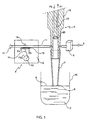
- Figure 1 shows a schematic view of a sampling device or level detection (free surface) according to the invention which allows the implementation of the sampling or detection and uses a means generating a pressure variation.
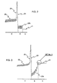
- Figure 2 shows a view of the electrical signal at the output of the pressure sensor viewed by an oscilloscope, when using a device according to FIG. 1 in the case non-wetting liquid.
- Figure 3 shows a view identical to Figure 2 in the case of a wetting liquid.
- FIG. 4 represents a detail D of FIG. 3.
- Figure 5 shows a sectional view at the lower end of the nozzle which is flush with the surface of a non-wetting liquid.
- Figure 6 shows a view identical to Figure 5 in the case of a wetting liquid.
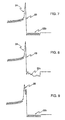
- FIG. 7 represents a view of a conventional electrical signal at the output of the pressure displayed by an oscilloscope.
- FIG. 8 represents a view of an electrical signal identical to that of FIG. 7 but disturbed by the presence of numerous small bubbles on the surface of the constituent sample a foam.
- FIG. 9 represents a view of an electrical signal identical to FIG. 7 but disturbed by the presence of an air bubble inside the sample, air bubble which is aspirated by the suction-sampling device.
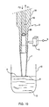
- FIG. 10 represents a schematic view of a sampling or level detection according to the invention, which allows the implementation of the sampling process or detection and uses a means generating an air flow.
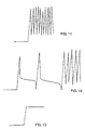
- Figure 11 shows a view of the electrical signal at the output of the pressure sensor viewed by an oscilloscope, when using a device according to figure 10, the tip coming directly into contact with the free surface of a liquid.
- Figure 12 shows a view identical to Figure 11 in the case where the nozzle enters indirectly in contact with the free surface of a liquid since there are bubbles.
- FIG. 13 represents a view identical to FIGS. 11 and 12 in the case where the tip comes into contact with the free surface of a solid.
- outcrop In the rest of the text, the term outcrop must be understood as being equivalent to get in touch.
- the walls internal or external lateral are soiled or not, before sampling, depending on whether said biological sample is a wetting or non-wetting liquid.
- the outcrop should ability to allow sampling without creating air bubbles or other gas with minimal soiling possible outside the nozzle.
- This device 1 is essentially constituted by a pipette 3 which allows the sampling of a biological sample 2 contained inside an analysis cuvette 10.
- the pipette 3 essentially consists of an external body 18 containing a piston 19.
- seal 20 between the piston 19 and the body 18 of the pipette 3.
- the pipette 18 has the free end of the body, a nozzle 7, also called a cone or sampling point.
- the present invention proposes to associate with the pipette 3 previously described, a means making it possible to generate a pressure variation, generally referenced 4 in FIG. 1.
- a means making it possible to generate a pressure variation 4 is also associated a pressure sensor 5 which measures the pressure and pressure variations when using the pipette 3.
- a pressure sensor 5 which measures the pressure and pressure variations when using the pipette 3.
- the object of the present invention is therefore also to detect the free surface 9 of a sample 2 whether this is wetting or not.
- the inside of the nozzle 7 is associated with both the pressure sensor 5 and the means generating a pressure variation 4.
- the means generating a pressure variation 4 is constituted by a support 12 which may optionally be integrated into a machine, not shown in the figures.
- This support 12 consists, for example, of the carcass or the structure of the automaton.
- This structure 12 acts as a support for a crankshaft 13 to which it is connected by a rotation axis.
- the crankshaft 13 is also associated with one of the ends of a connecting rod 14.
- the other end of this connecting rod 14 is in turn connected to a pressure roller 15 whose movement will be alternating according to F4 and F5 to allow compression between the pressure roller 15 and an anvil 16 of a flexible pipe 11.
- the anvil 16 is in fact integral with the support 12 and cannot move, which is not the case. in the case of the pressure roller 15.
- the flexible pipe 11 has two ends; a first end is plugged via a plug 17 while the other end is mechanically connected to the pipette 3. More specifically, the interior of the flexible pipe 11 is in direct relationship with the inside of the pipette 3 at the level of the space delimited by the body of the pipette 18, piston 19 and nozzle 7. It is therefore easy to understand that the engine does not represented in the figures will actuate in rotation, according to F3, the crankshaft 13, the movement of the pressure roller 15 will be carried out according to F4 then F5 to allow, on the one hand, compression and, on the other hand, the decompression of the flexible pipe 11 against the anvil 16.
- the pipe 11 When the movement of the roller 15 will be carried out according to F4, the pipe 11 will be pressed and there will be an air flow which will reach the within the pipette 3.
- the pressure roller 15 When, on the contrary, the pressure roller 15 will take place according to F5, the pressure exerted on the pipe 11 will be eliminated and said pipe 11 will be able to suck back the air which had been injected inside the body 18 of the pipette 3.
- the movement of the pressure roller 15 is on average a few Hertz to a few hundred Hertz.
- the pipe 11 is chosen so that the volume moved, that is to say sucked up and driven back, from a few nanoliters to a few microliters.
- each signal transmitted by the pressure sensor 5 essentially comprises three well-defined zones: A, B and C.
- the electrical signal at the output of sensor 5 corresponds to the position before there is contact between the end 8 of the nozzle 7 and the sample 2.
- the signal from sensor 5 corresponds to the position after there has been contact between end 8 and sample 2, but before aspiration by pipette 3.
- the signal corresponds to the position after contact between the end 8 and the sample 2, but after aspiration.
- Zone A1 corresponds to a signal for measuring the atmospheric pressure before the means 4 generating a pressure variation is put Operating.
- Zone A2 corresponds to a signal for measuring atmospheric pressure after the means 4 generating a pressure variation has been put into operation. So signal A1 is completely flat, whereas with A2 there is a slight amplitude due to air movements according to F4 and F5.
- This technique thus makes it possible to detect the free surface 9 of a biological sample 2 whatever the wetting or non-wetting nature of this sample 2.
- the present invention therefore relates to a method for taking a sample biological 2 via a suction-discharge device, a detection process of the free surface 9 of a biological sample 2 via, optionally, this same device. Finally, it relates to a device 1 for taking a sample 2, such as a pipette 3, and an apparatus for detecting the free surface of a biological sample.
- the invention therefore consists in injecting into the air space trapped in the nozzle 7 of draws an air flow. This flow of injected air, disturbing the precision of the sample, is immediately re-aspirated. We then obtain a back-and-forth system of a small amount of air of about a fraction of micro liter, see the curves of figures 2 to 4 and 7 at 9.
- This quantity is small enough compared to the quantities of moving air ensuring the correct volume required for pumping the liquid dose.
- This air flow is injected then sucked in at a speed fast enough that it had no effect on movement liquid at the orifice of the sampling tip, so the cycle suction / delivery is executed in a few milliseconds.
- the sensor pressure 5 reacts at a speed of the order of 100 micro seconds. At this speed, the liquid is not able to enter the nozzle 7.
- This system finds a particularly advantageous use in the case of liquid to low surface tension which comes into contact with the orifice of the sampling tip 7.
- this invention makes it possible to qualify the geometry of the end of the cone since if this end has roughness due for example to poor molding the micro flow of incoming and outgoing air is disturbed resulting in a change in the variation easily detectable pressure using the same pressure sensor 5.
- Air flows and refluxes are generated via a micro pump 4 operating on the crank connecting rod principle compressing a micro silicone hose 11, by example, whose inner capillary channel is of small diameter of the order of a few tenths of millimeters.
- the pipe 11 is alternately deformed and restored in its initial shape, thereby generating an air flow and reflux respectively.
- These air flows and refluxes are transmitted, via the hose, to the internal chamber of the sampling nozzle 7.
- one of the two ends of the pipe 11 is connected to said internal chamber of the sampling tip 7.
- the other end of this pipe 11 is closed with a plug 17.
- the pressure sensor 5, on the other hand, is in direct connection with the air channel of the pumping of the pipette, the pipette is of a standard type operating according to the known principle moving a mattress.
- the different types of electronic signals from the micro pressure sensor 5 are standard and can be used by any micro computer programmed to detect a signal of a few millivolts becoming instantly (a few milliseconds) a few hundred millivolts.
- volume of flow and reflux air for example from a few fractions of micro liters to a few micro liters, as well as varying the pulsation frequency, enabling said volume of air to be pulsed, from a few tens of Hertz to a few hundred Hertz, without departing from the scope of the invention.
- the air flow can be generated by other systems, such as micro speaker waterproof whose sound membrane acts like a pump membrane.
- the cavity sealed against the speaker traps a small volume of air which is then injected at the top of the sampling tip 7.
- the invention described above is used as a system for detecting the level of a liquid to be sampled 2. It can also have another functionality linked to the total clogging of the sampling tip 7, when the end of said tip is flush with the liquid. This system also makes it possible to detect a partial blockage of said sampling tip 7, by example when a biological liquid 2 is dried or crystallized at one of the ends or also inside this sampling tip 7.
- the invention in this case is capable of detecting the formation of a coalescence of the liquid; this coalescence generates at minus a ring of liquid which behaves like a fragile membrane. The flow and the reflux the volume of air ejected into the nozzle 7 is therefore disturbed, which results in a very low pressure variation which is detected by the pressure sensor 5. If at the same time, said nozzle 7 does not immerse in the liquid to be sampled 2, it can be deduced therefrom that the tip of sample 7 is imperfectly emptied, a second ejection cycle in this case can be undertaken.
- the present invention provides an apparatus which works only on the air mattress above the liquid column, which increases considerably the sensitivity of the pressure sensor that is used. So a low obstruction of the cone inlet results in a small variation in pressure which, compared to an unblocked cone signal reveals a partial blockage.
- the device according to the invention makes it possible to monitor the qualities of wettability of internal surfaces of the sampling cones 7 as well as the tensions of the different biological liquids. Indeed the peak of depression will be all the more high that the liquid will have little wetting and that the internal surface of the cone 7 will be hydrophobic. AT using a set of master curves stored in the management computer, it becomes possible to qualify biological liquids on these new criteria.
- the apparatus according to the present invention is judiciously positioned in the pump body 11; thus it is possible in the absence of sampling cone 7 to validate the tightness in all the parts contributing to the proper functioning.
- the control procedure can be performed before starting the analyzer by an artificial plugging of the end of the cone holder.
- An overpressure is generated by the pumping mechanism 4, within the pipette 3, and the pressure sensor 5 monitors for an extended time, for example a minute, the correct withstand this generated pressure.
- the invention therefore relates to a method for detecting the level of liquid by variation of pressure using a pressure sensor 5, associated with a pulsed air flow, that is to say obtained by injection of a small volume then re-aspiration of this volume.
- the air flow is of a frequency from a few Hertz to a few hundred Hertz.
- the volume of forced air is an amount varying from a few nanoliters to a few microliters.
- FIG. 7 therefore represents a conventional electrical signal at the output of the pressure 5 displayed by an oscilloscope. This signal breaks down as follows.
- FIG. 8 represents an electrical signal identical to that of FIG. 7 but disturbed by the presence of many small bubbles on the surface of the sample constituting a foam. Therefore in zone B, the variations generated by means 4 are much less regular 22c. This is linked to the fact that the pressure sensor 5 alternately detects the presence of liquid 2 and air. In this case the signal uses the references 21, 23, 24 and 25 exposed above but not the reference 22b replaced by the reference 22c.
- Figure 9 shows a view of an electrical signal identical to Figure 7 but also disturbed by the presence of an air bubble inside the sample, air bubble which is sucked by the suction-extraction device at zone C.
- This curve includes references 21, 22b and 25, but references 23 and 24 are absent because replaced by a depression 28 of the sample 2 in the end piece 7 disturbed by a bubble air.
- This invention detects leaks between the tip and the pipette, but also the presence of gas bubbles in the sample during sampling, imperfect cones emptied, the presence of a cone, partial plugging of a cone with a biological reagent.
- the invention still allows the qualification of hydrostatic forces (surface tension / wettability), the cone qualification (geometry / end molding), speed control of the device sampling, checking that the mechanism of said device does not leak.
- the pipette 3 can be of simpler structure than the pipette shown in Figure 1.
- this embodiment shown in Figure 10, there there is no presence of a means generating a pressure variation 4.
- the object of this invention resides in the use of the piston 19 to create a flow continuous and constant air at the nozzle 7.
- the piston 19 went up to the maximum according to F1.
- the piston 19 is driven by the movement along F2 in order to drive, outside of the pipette 3 and said tip 7, the air contained therein. This air will therefore be evacuated at the level of the free lower end 8 of said end piece 7.
- the signal is first of all horizontal, on the left of the figure, and corresponds to atmospheric pressure or in any case to the pressure undergone by inside the pipette 3 and the nozzle 7 under the effect of the air flow generated by the piston 19.
- the line is transformed into a curve which increases and constitutes a certain number of successive peaks.
- this curve corresponds to the fact that the free end 8 of the nozzle 7 is at the free surface 9 of the liquid to be detected 2.
- the peaks correspond therefore to the creation of air bubbles within the liquid.
Landscapes
- Physics & Mathematics (AREA)
- Health & Medical Sciences (AREA)
- Life Sciences & Earth Sciences (AREA)
- Chemical & Material Sciences (AREA)
- Analytical Chemistry (AREA)
- Biochemistry (AREA)
- General Health & Medical Sciences (AREA)
- General Physics & Mathematics (AREA)
- Immunology (AREA)
- Pathology (AREA)
- Automatic Analysis And Handling Materials Therefor (AREA)
- Sampling And Sample Adjustment (AREA)
- Measurement Of Levels Of Liquids Or Fluent Solid Materials (AREA)
- Devices For Use In Laboratory Experiments (AREA)
- Feeding, Discharge, Calcimining, Fusing, And Gas-Generation Devices (AREA)
Claims (8)
- Verfahren zur Entnahme einer biologischen Probe über eine manuelle oder automatische Saug- und Pumpvorrichtung, die in einen Automaten integriert ist oder nicht, das darin besteht,dass ein Mittel betätigt wird, das eine Druckänderung und/oder einen Luftstrom im Inneren der Vorrichtung erzeugt,dass das freie untere Ende der Saug- und Pumpvorrichtung so positioniert wird, dass es mit der freien Oberfläche der biologischen Probe bündig ist,dass die Druckänderung und/oder ein Luftstrom in Inneren der Vorrichtung erfasst wird, wobei diese Erfassung dem Bündigsein des unteren Endes der Vorrichtung mit der freien Oberfläche der biologischen Probe entspricht, unddass eine Menge dieser Probe mit Hilfe der Vorrichtung in bündiger Stellung durch Absaugung entnommen wird, was verhindert, dass die äußeren Seitenwände der Vorrichtung durch die Probe anders verunreinigt werden als durch das, was durch den mehr oder weniger benetzenden Charakter der Probe verursacht wird.
- Verfahren nach Anspruch 1, dadurch gekennzeichnet, dass die Änderung des angesaugten und gepumpten Volumens zwischen einigen Nanolitern (nl) und einigen Mikrolitern (µl) beträgt und/oder die ständige Druckänderung, mit anderen Worten die Frequenz, zwischen einigen Hertz und einigen Hunderten Hertz (Hz) beträgt.
- Verfahren nach einem der Ansprüche 1 oder 2, dadurch gekennzeichnet, dass der Luftstrom zwischen 10 und 50 µl pro Sekunde und vorzugsweise 20 bis 30 µl pro Sekunde beträgt.
- Vorrichtung (1), die in einen Automaten integriert ist oder nicht, zur manuellen oder automatischen Entnahme einer biologischen Probe (2), umfassend:dadurch gekennzeichnet, dass sie ferner Mittel (6) zur Analyse der von dem oder den Fühlern (5) gelieferten Signale aufweist, um die Entnahme zu gestatten, wenn das freie untere Ende (8) der Saug- und Pumpvorrichtung mit der freien Oberfläche (9) der biologischen Probe (2) bündig ist, ohne dass die äußeren Seitenwande der Vorrichtung (1) durch die Probe (2) anders als durch das verschmutzt sind, was ggf. durch den mehr oder weniger benetzenden Charakter der Probe verursacht wird.mindestens ein Mittel, das eine Druckänderung (4) oder einen Luftstrom (19) im Inneren der Vorrichtung (1) im Ruhezustand erzeugt, undmindestens einen Druckfühler (5) zum Erfassen einerseits der Druckänderung im Ruhezustand oder eines von dieser Druckänderung abweichenden Drucks oder andererseits eines Drucks, der von dem durch den Luftstrom erzeugten Druck im Inneren der Vorrichtung (1) abweicht,
- Automatische Vorrichtung nach Anspruch 4, dadurch gekennzeichnet, dass das eine Druckänderung erzeugende Mittel (4) aus einem Schlauch (11) besteht, der durch jeden Hinund Herbewegungsmechanismus (12-17) regelmäßig komprimiert und dekomprimiert werden kann.
- Vorrichtung nach Anspruch 4, dadurch gekennzeichnet, dass das den Luftstrom erzeugende Mittel (19) aus dem Kolben (19) der Pipette (3) besteht, wenn dieser die Luft aus der Pipette (3) nach außen ausstößt.
- Vorrichtung nach einem der Ansprüche 4 bis 6, dadurch gekennzeichnet, dass das freie untere Ende (8) der Vorrichtung (1) aus einem Einwegaufsatz (7) besteht.
- Verfahren zum Erfassen einer partiellen oder vollständigen Verstopfung im Bereich einer manuellen oder automatischen Vorrichtung (1) zur Entnahme einer biologischen Probe (2) nach einem der Ansprüche 4 bis 7, das darin besteht,dass ein Mittel betätigt wird, das eine Druckänderung und/oder einen Luftstrom im Inneren der Vorrichtung erzeugt, unddass eine Druckänderung gemessen wird, die von der normalen Druckänderung im Inneren der Vorrichtung abweicht und die durch eine partielle oder vollständige Verstopfung des freien unteren Endes der Vorrichtung verursacht wird.
Applications Claiming Priority (5)
| Application Number | Priority Date | Filing Date | Title |
|---|---|---|---|
| FR9804144 | 1998-04-01 | ||
| FR9804144A FR2777085A1 (fr) | 1998-04-01 | 1998-04-01 | Procede de prelevement d'un echantillon biologique par l'intermediaire d'un appareil d'aspiration-refoulement |
| FR9807884 | 1998-06-22 | ||
| FR9807884A FR2777086B3 (fr) | 1998-04-01 | 1998-06-22 | Procede de prelevement et de detection de surface d'un echantillon biologique par l'intermediaire d'un appareil d'aspiration-refoulement |
| PCT/FR1999/000728 WO1999050674A1 (fr) | 1998-04-01 | 1999-03-29 | Procede de prelevement d'un echantillon biologique |
Publications (2)
| Publication Number | Publication Date |
|---|---|
| EP1066532A1 EP1066532A1 (de) | 2001-01-10 |
| EP1066532B1 true EP1066532B1 (de) | 2002-07-03 |
Family
ID=26234241
Family Applications (1)
| Application Number | Title | Priority Date | Filing Date |
|---|---|---|---|
| EP99910452A Expired - Lifetime EP1066532B1 (de) | 1998-04-01 | 1999-03-29 | Verfahren zur probenentnahme einer biologischen probe |
Country Status (8)
| Country | Link |
|---|---|
| US (2) | US6641545B1 (de) |
| EP (1) | EP1066532B1 (de) |
| JP (1) | JP2002510056A (de) |
| AU (1) | AU763656B2 (de) |
| CA (1) | CA2324930A1 (de) |
| DE (1) | DE69902024T2 (de) |
| FR (1) | FR2777086B3 (de) |
| WO (1) | WO1999050674A1 (de) |
Cited By (2)
| Publication number | Priority date | Publication date | Assignee | Title |
|---|---|---|---|---|
| DE102005060862B3 (de) * | 2005-12-20 | 2007-06-28 | Stratec Biomedical Systems Ag | Verfahren und Vorrichtung zur Beurteilung eines Dosiervorgangs |
| US7482939B2 (en) | 2005-11-15 | 2009-01-27 | Roche Molecular Systems, Inc. | Electrical drop surveillance |
Families Citing this family (25)
| Publication number | Priority date | Publication date | Assignee | Title |
|---|---|---|---|---|
| US7439076B1 (en) * | 2000-06-30 | 2008-10-21 | Hitachi, Ltd. | Liquid dispensing method and device |
| US7479391B2 (en) * | 2004-12-10 | 2009-01-20 | Tecan Trading Ag | Pipetting apparatus with integrated liquid level and/or gas bubble detection |
| DE102004063358A1 (de) * | 2004-12-23 | 2006-07-06 | Georg-August-Universität Göttingen | Verfahren zur Bestimmung der Viskosität und Viskosimeter |
| FR2898285B1 (fr) | 2006-03-13 | 2008-04-18 | Biomerieux Sa | Dispositif, utilisation et procede de prelevement d'un liquide |
| US7870797B2 (en) * | 2006-04-03 | 2011-01-18 | Artel, Inc. | Apparatus and method for aspirating and dispensing liquid |
| JP4753770B2 (ja) * | 2006-04-06 | 2011-08-24 | ベックマン コールター, インコーポレイテッド | 分注装置における配管内の気泡の有無判定方法および分注装置 |
| JP5658566B2 (ja) * | 2007-09-29 | 2015-01-28 | イーアイ・スペクトラ・エルエルシー | 計装ピペット先端 |
| US7634378B2 (en) * | 2007-11-30 | 2009-12-15 | Siemens Healthcare Diagnostics Inc. | Detection of insufficient sample during aspiration with a pipette |
| JP5192264B2 (ja) * | 2008-03-07 | 2013-05-08 | ベックマン コールター, インコーポレイテッド | 気泡有無判定方法および分注装置 |
| US8231842B2 (en) * | 2010-01-22 | 2012-07-31 | Tecan Trading Ag | Positive displacement pump with pressure sensor |
| JP2013076674A (ja) * | 2011-09-30 | 2013-04-25 | Fujifilm Corp | 分注装置および吸引ノズル位置制御方法 |
| CN102607667B (zh) * | 2012-03-05 | 2014-01-15 | 太原理工大学 | 基于虚拟仪器智能相机的煤仓煤位检测方法 |
| US10082452B2 (en) | 2013-02-05 | 2018-09-25 | Pocared Diagnostics Ltd. | Filter arrangement and method for using the same |
| EP3058352B1 (de) * | 2013-10-17 | 2019-03-06 | Siemens Healthcare Diagnostics Inc. | Verfahren und vorrichtung zur messung eines saugdrucks |
| WO2015092844A1 (ja) * | 2013-12-16 | 2015-06-25 | 株式会社島津製作所 | 液採取装置及びその液採取装置を備えた自動分析装置 |
| CA2957420A1 (en) | 2014-08-15 | 2016-02-18 | Biomerieux, Inc. | Methods, systems, and computer program products for verifying dispensing of a fluid from a pipette |
| CN111609168B (zh) * | 2015-09-14 | 2021-12-07 | 日商乐华生命科學有限公司 | 切换阀、及具备切换阀的吸入喷出装置 |
| WO2019060716A1 (en) * | 2017-09-25 | 2019-03-28 | Freenome Holdings, Inc. | SAMPLE EXTRACTION METHODS AND SYSTEMS |
| WO2019193404A1 (en) | 2018-04-06 | 2019-10-10 | Muscle Lab Canada Inc. | Integrated pipetting apparatus |
| JP7079352B2 (ja) * | 2018-07-03 | 2022-06-01 | シーメンス・ヘルスケア・ダイアグノスティックス・インコーポレイテッド | ピペット装置の近接感知のために無脈動空気流を生成する小型圧電空気ポンプ |
| EP3872496B1 (de) * | 2018-10-26 | 2025-07-23 | Hitachi High-Tech Corporation | Automatisierter analysator |
| KR102170779B1 (ko) * | 2019-02-07 | 2020-10-28 | 주식회사 위코테크 | 수질 측정방법 |
| JP7417463B2 (ja) * | 2020-04-24 | 2024-01-18 | 株式会社日立ハイテク | 分注装置、自動分析装置、分注方法 |
| CA3191169A1 (en) * | 2020-08-10 | 2022-02-17 | Agilent Technologies, Inc. | Pressure-based liquid level detection |
| CN115824712B (zh) * | 2022-11-30 | 2023-08-11 | 江西怡杉环保股份有限公司 | 一种采样计量定量全过程电数据处理方法 |
Family Cites Families (6)
| Publication number | Priority date | Publication date | Assignee | Title |
|---|---|---|---|---|
| US3982438A (en) * | 1975-06-23 | 1976-09-28 | The Salk Institute For Biological Studies | Multiple sample pipetting apparatus |
| EP0341438A3 (de) * | 1988-05-13 | 1990-11-28 | Abbott Laboratories | Pneumatischer Sensor |
| US4846003A (en) * | 1988-06-08 | 1989-07-11 | Beckman Instruments, Inc. | Acoustic impedance system for pipette tip detection |
| FI90207C (fi) * | 1992-05-04 | 1994-01-10 | Wallac Oy | Pipettilaitteisto |
| US5723795A (en) * | 1995-12-14 | 1998-03-03 | Abbott Laboratories | Fluid handler and method of handling a fluid |
| JP2985816B2 (ja) * | 1997-02-04 | 1999-12-06 | 日本電気株式会社 | 液体採取装置 |
-
1998
- 1998-06-22 FR FR9807884A patent/FR2777086B3/fr not_active Expired - Lifetime
-
1999
- 1999-03-29 AU AU29403/99A patent/AU763656B2/en not_active Ceased
- 1999-03-29 EP EP99910452A patent/EP1066532B1/de not_active Expired - Lifetime
- 1999-03-29 JP JP2000541531A patent/JP2002510056A/ja active Pending
- 1999-03-29 CA CA002324930A patent/CA2324930A1/fr not_active Abandoned
- 1999-03-29 DE DE69902024T patent/DE69902024T2/de not_active Expired - Lifetime
- 1999-03-29 WO PCT/FR1999/000728 patent/WO1999050674A1/fr not_active Ceased
-
2000
- 2000-09-29 US US09/675,648 patent/US6641545B1/en not_active Expired - Lifetime
-
2003
- 2003-08-14 US US10/640,646 patent/US7097623B2/en not_active Expired - Fee Related
Cited By (2)
| Publication number | Priority date | Publication date | Assignee | Title |
|---|---|---|---|---|
| US7482939B2 (en) | 2005-11-15 | 2009-01-27 | Roche Molecular Systems, Inc. | Electrical drop surveillance |
| DE102005060862B3 (de) * | 2005-12-20 | 2007-06-28 | Stratec Biomedical Systems Ag | Verfahren und Vorrichtung zur Beurteilung eines Dosiervorgangs |
Also Published As
| Publication number | Publication date |
|---|---|
| FR2777086B3 (fr) | 2000-06-09 |
| US6641545B1 (en) | 2003-11-04 |
| AU763656B2 (en) | 2003-07-31 |
| AU2940399A (en) | 1999-10-18 |
| DE69902024T2 (de) | 2003-02-06 |
| EP1066532A1 (de) | 2001-01-10 |
| US20040048393A1 (en) | 2004-03-11 |
| CA2324930A1 (fr) | 1999-10-07 |
| FR2777086A1 (fr) | 1999-10-08 |
| DE69902024D1 (de) | 2002-08-08 |
| US7097623B2 (en) | 2006-08-29 |
| WO1999050674A1 (fr) | 1999-10-07 |
| JP2002510056A (ja) | 2002-04-02 |
Similar Documents
| Publication | Publication Date | Title |
|---|---|---|
| EP1066532B1 (de) | Verfahren zur probenentnahme einer biologischen probe | |
| FR2927999A1 (fr) | Viscosimetre comprenant un systeme de pipetage, a precision amelioree et conception simplifiee | |
| EP1327152B1 (de) | Vorrichtung zur abgabe von flüssigkeit | |
| EP2255161A1 (de) | Verfahren zur messung der ausgegebenen menge einer flüssigkeit in einem behälter durch messung von dessen kapazität | |
| FR2614422A1 (fr) | Electrode enzymatique et module a electrode perfectionnes et leur procede d'utilisation | |
| EP0321358B1 (de) | Blutentnahmevorrichtung | |
| FR3003033A1 (fr) | Dispositif de prelevement d'un echantillon de liquide par capillarite et procede d'analyse associe | |
| FR2629209A1 (fr) | Procede pour mesurer l'hematocrite et echantillonner separement le constituant plasmatique et le constituant globulaire du sang | |
| EP2056105A1 (de) | Vorrichtung zur Bodenerosionsmessung unterhalb der Bodenoberfläche und Messverfahren | |
| WO2013072643A2 (fr) | Procede optique pour piloter le deplacement d'un outil de prelevement | |
| WO2022184984A1 (fr) | Capteur de volume et de débit, injecteur associé | |
| EP3877744B1 (de) | Mikrofluidische probenvorbereitungsvorrichtung mit hoher wiederholbarkeit | |
| FR2777085A1 (fr) | Procede de prelevement d'un echantillon biologique par l'intermediaire d'un appareil d'aspiration-refoulement | |
| EP0351256B1 (de) | Vereinfachte Entnahme- und Verteilungsvorrichtung für einen automatischen Blutanalysator | |
| FR2905379A1 (fr) | Dispositif de collecte et de separation de particules et de microorganismes presents dans l'air ambiant | |
| FR2827318A1 (fr) | Dispositif permettant d'evaluer la resistance mecanique d'un sol ou analogue | |
| WO2003052359A1 (fr) | Dispositif pour la mesure capacitative d’un niveau de remplissage | |
| FR2579467A1 (fr) | Chambre de detection de fuites d'air pour dispositif de drainage pleural | |
| FR2708341A1 (fr) | Procédé de dosage, notamment micro-dosage d'un liquide; application à l'obtention de dilutions contrôlées, notamment des dilutions nanovolumétriques. | |
| FR2846254A1 (fr) | Dispositif de filtration integrant le controle du volume echantillonne | |
| BE1004241A7 (fr) | Dispositif d'analyse d'un echantillon de liquide et procede utilisant un tel dispositif. | |
| EP2660594B1 (de) | Elektronisches Gerät zur Überwachung der Weinbereitung | |
| FR2672994A1 (fr) | Capteur de pression osmotique pour mesures en continu. | |
| FR2496259A1 (fr) | Dispositif de pipetage, notamment pour le melange d'au moins deux liquides | |
| FR3137268A1 (fr) | Procédé d’analyse d’une sueur présente sur une peau d’un utilisateur et dispositif d’analyse pour mettre en œuvre un tel procédé |
Legal Events
| Date | Code | Title | Description |
|---|---|---|---|
| PUAI | Public reference made under article 153(3) epc to a published international application that has entered the european phase |
Free format text: ORIGINAL CODE: 0009012 |
|
| 17P | Request for examination filed |
Effective date: 20001017 |
|
| AK | Designated contracting states |
Kind code of ref document: A1 Designated state(s): DE ES FR GB IT |
|
| 17Q | First examination report despatched |
Effective date: 20010427 |
|
| GRAG | Despatch of communication of intention to grant |
Free format text: ORIGINAL CODE: EPIDOS AGRA |
|
| GRAG | Despatch of communication of intention to grant |
Free format text: ORIGINAL CODE: EPIDOS AGRA |
|
| GRAH | Despatch of communication of intention to grant a patent |
Free format text: ORIGINAL CODE: EPIDOS IGRA |
|
| GRAH | Despatch of communication of intention to grant a patent |
Free format text: ORIGINAL CODE: EPIDOS IGRA |
|
| GRAA | (expected) grant |
Free format text: ORIGINAL CODE: 0009210 |
|
| AK | Designated contracting states |
Kind code of ref document: B1 Designated state(s): DE ES FR GB IT |
|
| PG25 | Lapsed in a contracting state [announced via postgrant information from national office to epo] |
Ref country code: IT Free format text: LAPSE BECAUSE OF FAILURE TO SUBMIT A TRANSLATION OF THE DESCRIPTION OR TO PAY THE FEE WITHIN THE PRESCRIBED TIME-LIMIT;WARNING: LAPSES OF ITALIAN PATENTS WITH EFFECTIVE DATE BEFORE 2007 MAY HAVE OCCURRED AT ANY TIME BEFORE 2007. THE CORRECT EFFECTIVE DATE MAY BE DIFFERENT FROM THE ONE RECORDED. Effective date: 20020703 |
|
| REF | Corresponds to: |
Ref document number: 69902024 Country of ref document: DE Date of ref document: 20020808 |
|
| GBT | Gb: translation of ep patent filed (gb section 77(6)(a)/1977) |
Effective date: 20020920 |
|
| PG25 | Lapsed in a contracting state [announced via postgrant information from national office to epo] |
Ref country code: ES Free format text: LAPSE BECAUSE OF FAILURE TO SUBMIT A TRANSLATION OF THE DESCRIPTION OR TO PAY THE FEE WITHIN THE PRESCRIBED TIME-LIMIT Effective date: 20030130 |
|
| PLBE | No opposition filed within time limit |
Free format text: ORIGINAL CODE: 0009261 |
|
| STAA | Information on the status of an ep patent application or granted ep patent |
Free format text: STATUS: NO OPPOSITION FILED WITHIN TIME LIMIT |
|
| 26N | No opposition filed |
Effective date: 20030404 |
|
| REG | Reference to a national code |
Ref country code: FR Ref legal event code: PLFP Year of fee payment: 17 |
|
| PGFP | Annual fee paid to national office [announced via postgrant information from national office to epo] |
Ref country code: DE Payment date: 20150327 Year of fee payment: 17 |
|
| PGFP | Annual fee paid to national office [announced via postgrant information from national office to epo] |
Ref country code: GB Payment date: 20150327 Year of fee payment: 17 Ref country code: FR Payment date: 20150317 Year of fee payment: 17 |
|
| REG | Reference to a national code |
Ref country code: DE Ref legal event code: R119 Ref document number: 69902024 Country of ref document: DE |
|
| GBPC | Gb: european patent ceased through non-payment of renewal fee |
Effective date: 20160329 |
|
| REG | Reference to a national code |
Ref country code: FR Ref legal event code: ST Effective date: 20161130 |
|
| PG25 | Lapsed in a contracting state [announced via postgrant information from national office to epo] |
Ref country code: DE Free format text: LAPSE BECAUSE OF NON-PAYMENT OF DUE FEES Effective date: 20161001 Ref country code: FR Free format text: LAPSE BECAUSE OF NON-PAYMENT OF DUE FEES Effective date: 20160331 Ref country code: GB Free format text: LAPSE BECAUSE OF NON-PAYMENT OF DUE FEES Effective date: 20160329 |