EP1066855A2 - Abseilgerät - Google Patents
Abseilgerät Download PDFInfo
- Publication number
- EP1066855A2 EP1066855A2 EP00890206A EP00890206A EP1066855A2 EP 1066855 A2 EP1066855 A2 EP 1066855A2 EP 00890206 A EP00890206 A EP 00890206A EP 00890206 A EP00890206 A EP 00890206A EP 1066855 A2 EP1066855 A2 EP 1066855A2
- Authority
- EP
- European Patent Office
- Prior art keywords
- guide
- parts
- guide part
- rope
- descender
- Prior art date
- Legal status (The legal status is an assumption and is not a legal conclusion. Google has not performed a legal analysis and makes no representation as to the accuracy of the status listed.)
- Withdrawn
Links
- 238000004804 winding Methods 0.000 claims description 26
- 238000013461 design Methods 0.000 claims description 5
- 238000003780 insertion Methods 0.000 abstract description 3
- 230000037431 insertion Effects 0.000 abstract description 3
- 238000004519 manufacturing process Methods 0.000 description 4
- 239000000725 suspension Substances 0.000 description 4
- 230000002349 favourable effect Effects 0.000 description 3
- 210000003128 head Anatomy 0.000 description 2
- 239000000463 material Substances 0.000 description 2
- 238000003860 storage Methods 0.000 description 2
- 229920002430 Fibre-reinforced plastic Polymers 0.000 description 1
- 229910000831 Steel Inorganic materials 0.000 description 1
- 230000004323 axial length Effects 0.000 description 1
- 230000000903 blocking effect Effects 0.000 description 1
- 238000004891 communication Methods 0.000 description 1
- 238000010276 construction Methods 0.000 description 1
- 238000011161 development Methods 0.000 description 1
- 230000018109 developmental process Effects 0.000 description 1
- 230000000694 effects Effects 0.000 description 1
- 239000011151 fibre-reinforced plastic Substances 0.000 description 1
- 238000012423 maintenance Methods 0.000 description 1
- 238000000034 method Methods 0.000 description 1
- 238000004806 packaging method and process Methods 0.000 description 1
- 239000004033 plastic Substances 0.000 description 1
- 229920003023 plastic Polymers 0.000 description 1
- 239000007787 solid Substances 0.000 description 1
- 239000010959 steel Substances 0.000 description 1
- 238000012360 testing method Methods 0.000 description 1
- 238000012549 training Methods 0.000 description 1
- 238000003466 welding Methods 0.000 description 1
Images



Classifications
-
- A—HUMAN NECESSITIES
- A62—LIFE-SAVING; FIRE-FIGHTING
- A62B—DEVICES, APPARATUS OR METHODS FOR LIFE-SAVING
- A62B1/00—Devices for lowering persons from buildings or the like
- A62B1/06—Devices for lowering persons from buildings or the like by making use of rope-lowering devices
Definitions
- the invention relates to a descender according to the introductory part Part of claim 1.
- an up / down rope device is known, at which a roll-shaped winding axis between side support parts is stored.
- a rope stop device provided that if the rope run is too fast Function occurs.
- a rope guide device is provided, the on the one hand, a fixed plate part provided with openings between the two supporting parts and on the other hand additional Guide rollers for which a separate storage on the Support parts is required.
- the present descender can because of its simplicity advantageous as a rescue device for cable cars, for abseiling People, are used, it is also compared to Prior art has the advantage that rappelling in both directions of rotation is possible in the same way.
- the Descender (or pendulum descender) is in its simple Version not self-braking or stopping; the rope can but when rappelling e.g. by hand or like this as well is known per se, with the help of a rope stop device or Modulation device are braked.
- the rope is sliding friction-braked via the winding axis acting as a braking axis.
- the Guide openings are slit-shaped and in Extend circumferential direction of the annular guide parts.
- the slot-shaped guide openings over a circular arc corresponding to a central angle of 90 ° to 135 °, in particular 105 ° to 120 °, extend.
- the or the Guide webs preferably protrude radially inwards to just under the winding axis, with a gap in the range of 0.5 mm or 1 mm between the circumference of the winding axis and the inner one Edge of the guide bar or bars can be present.
- each guide part with one of the side support parts connected e.g. is welded or in one piece.
- the supporting parts protrude with cranked Straps are designed with hanging eyes. If the descender thus on a hanging part inserted through its hanging eyes, e.g. a carabiner that is hanging is automatic also a twisting of the support parts or the firmly connected Avoided guide parts.
- the supporting parts especially if they are provided with the cranked tabs, a comfortable handle for turning the guide parts relatively to each other.
- the winding axis act as a braking axis for the rope can, it becomes solid, e.g. with the help of bolts, with one of the lateral support parts connected.
- the other supporting part is then rotatable relative to the winding axis.
- the winding axis has a central hole, through which a bearing pin is inserted, which also the two crosses lateral support parts, and the one with a head on the outside a supporting part rests.
- the washer is on the Gradation of the bearing pin.
- the two annular Guide parts are of the same design and one in the ring wall have arranged slot-shaped guide opening, the at one end via a connecting slot to that side of the guide part is open to the other guide part is adjacent. Due to the identical design of the guide parts the production as well as the storage is simplified.
- the guide bar is on the wider guide part seen approximately in the center in the axial direction
- Position protrudes radially inwards from the inside of the ring wall and preferably over an arc corresponding to one Central angle extends from 105 ° to 110 °.
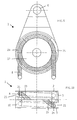
- the descender shown in Figure 1 is generally 1 denotes and has two supporting parts 2, 3 located on the outside that with cranked tabs 4 and 5 protruding upwards are provided, which with suspension eyelets 6 for pushing through one Suspension part, such as a carabiner (not shown), have for hanging the descender 1.
- the descender 1 is furthermore with a generally indicated in Fig.1, only schematically illustrated cable guide device 7 provided to guide a rope 8 when abseiling.
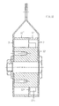
- each support member 2, 3 is fixed connected to an annular guide part 9 or 10.
- the fixed connection between support part 2 or 3 and guide part 9 or 10 can be done for example by welding, as in Figure 2 is illustrated schematically at 11; It is also possible, the guide parts 9, 10 each in one piece with the To produce support parts 2, 3, so that then two bowl-shaped Housing parts are obtained in the embodiment shown are each provided with a cranked tab 4 or 5.
- a Brake axis acting rigid winding axis 12 provided with one supporting part 2 fixed, for example by means of bolts 13, connected is.
- This winding axis 12 is a bearing pin 14 penetrates in the middle, which with its head 15 on the outside Support part 2 is applied.
- the bearing pin is at the opposite end 14 graded at 16 and it ends there in one Diameter-smaller thread section 17 on which a nut 18 is screwed on with the interposition of a washer 19.
- the washer 19 is due to the gradation 16 formed shoulder of the bearing pin 14 and secures the other support part 3 on the winding axis 12, without it Rotatability on the bearing pin 14 or relative to the winding axis 12 and to prevent it from being connected to other supporting part 2.
- Each guide part 9 or 10 has one in its ring wall 20 Guide opening 21 for the rope (8 in Fig.1).
- This guide opening 21 is slit-shaped, i.e. it stretches according to a circular arc 22 (FIG. 3) in the circumferential direction, for example corresponding to a central angle of 105 °.
- the slot-shaped guide opening 21 is in the present embodiment 5 to the one outer axial side open, cf. also Fig.2, where the slot-shaped guide opening 21 on a guide part 9 can be seen (the slot-shaped guide opening of the other guide part 10 is on the not visible in this sectional view Front of the descender 1).
- the end of the slot-shaped guide opening 21 is at an angle to the middle side, i.e. that side of the guide part 9 (or 10), the other guide part in the assembled position 10 (or 9) is adjacent, extending connecting slot 23 intended.
- the two guide parts 9, 10 are mirror images of the descender 1 arranged to each other so that when twisted the guide parts 9, 10 in a position in which the connecting slots 23 directly opposite each other, a connection between the slot-shaped guide openings 21 in the two guide parts 9 and 10 is created.
- This situation is illustrated in Fig. 7 and 8, where there is also the in Fig. 2 to 6 illustrates rope 8 omitted for the sake of simplicity is.
- the rope 8 through the aligned, sloping connecting slots 23 inserted in the two guide parts 9, 10, so that it is inside the outer circumference of the guide parts 9, 10 rests on the winding axis 12, and the rope 8 then extends through the respective slot-shaped guide opening 21 outwards, i.e. to the outside of through the Guide parts 9, 10 together with the support parts 2, 3 formed housing.
- both are Guide parts 9, 10 in the area of the slot-shaped guide opening 21 with a radially inwardly projecting from the annular wall 20, along part of the edge of the guide opening 21 extending guide web 23 which is formed but not over the entire arc length of the slit-shaped Guide opening 21 extends, but only over a part of which, following the oblique connection slot 23, for example via an arc 25 corresponding to a Center angle of approximately 45 °.
- These guide webs 24 are can also be seen in particular from FIGS.
- the embodiment of the descender 1 according to the Fig.11 to 18 largely corresponds to that according to FIGS. 2 to 10, so that a repetition of the description, as far as similar components available, can be superfluous; corresponding components are identified by the same reference numbers.
- the diagrammatic view according to Fig.1 is accurate taken the embodiment of Fig.11 to 18 reproduces the is characterized in that two different, unequal wide guide parts 9 ', 10' are present, the guide openings are also designed differently, as below will be explained in more detail.
- the Winding axis 12 with bolts 13 to the other support part 3 connected is also designed differently, as below will be explained in more detail.
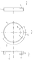
- the one, narrower annular guide part 9 ' as shown in Figure 12 and in particular in 13 to 15 with a slot-shaped guide opening 121 formed that open to one side of this guide part 9 ' is, namely to the side that in the assembled state, s. 12, the other guide part 10 'is adjacent.
- This slot-shaped guide opening 121 extends according to FIG. 13 for example via an arc 122 corresponding to one Central angle of 120 °.
- This arc 122 also includes a circular arc 125 corresponding to a central angle of approximately 60 ° to an end guide web 124, which of the Ring wall 120 protrudes radially inwards.
- This guide bar 124 can also be seen in the sectional view of Fig.12.
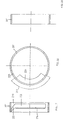
- the other, wider annular guide part 10 has one slit-shaped running within its ring wall 220 Guide opening 221, for example, over a circular arc 222 extends according to a central angle of approx. 110 °, and on both sides (see Fig. 17) through areas of the ring wall 220 is limited. Moreover, this is axially adjacent slot-shaped guide opening 221 within the axial extent of the guide part 10 'a protruding radially inward Guide web 224 is provided, which extends over a relatively large Circular arc extends, for example according to a central angle from approximately 105 ° to approximately 110 °.
- the wider guide part 10 ' can be almost twice as wide like the narrower guide part 9 ', and the guide web 224 can be roughly in the middle (according to Fig. 17 something from the Middle offset) so that when assembled through the guide web 124, which is on the end face of the guide part 9 ' is present, and the guide web 124 three approximately the same width Ring areas on the winding axis 12 to be defined Keep turns of the rope 8 separate.
- the individual components of the respective descender 1, in the embodiment according to Figure 2 to 10 as in that according to 11 to 18, can be metallic, for example made of steel, be carried out, but it is also conceivable, at least some Parts, such as the winding axis 12, made of a plastic material, in particular a fiber-reinforced plastic material, to manufacture. It is also conceivable in the circumferential direction to provide comparatively short guide openings that connected to one another via corresponding connecting slots can be brought when the guide parts against each other be twisted.
- the lateral support parts 2, 3 are, for example, simply disk-shaped and have lateral fastening elements; if necessary, the axis formed by the bearing pin 14 can also protrude laterally for mounting purposes.
Landscapes
- Health & Medical Sciences (AREA)
- General Health & Medical Sciences (AREA)
- Business, Economics & Management (AREA)
- Emergency Management (AREA)
- Storage Of Web-Like Or Filamentary Materials (AREA)
- Storing, Repeated Paying-Out, And Re-Storing Of Elongated Articles (AREA)
- Emergency Lowering Means (AREA)
Abstract
Description
gegebenenfalls kann auch die durch den Lagerbolzen 14 gebildete Achse für Halterungszwecke seitlich vorstehen.
Claims (14)
- Abseilgerät mit einer zwischen zwei Tragteilen (2, 3) gehaltenen Wickelachse für ein Seil (8) und mit einer Seilführungseinrichtung (7), dadurch gekennzeichnet, dass die Seilführungseinrichtung (7) zwei allgemein ringförmige, axial aneinander anliegende Führungsteile (9, 10; 9', 10') aufweist, die die Wickelachse (12) umgeben und relativ zueinander drehbar gelagert sind, und die je eine Führungsöffnung (21; 121, 221) für das Seil (8) in ihrer Ringwand (209; 120, 220) aufweisen, wobei die Führungsöffnungen (21; 121, 221) in der Betriebs- oder Abseilposition der Führungsteile (9, 10; 9', 10') voneinander getrennt vorliegen, in einer demgegenüber relativ zueinander verdrehten Position der Führungsteile (9, 10; 9', 10') zur Einführung oder Abnahme des Seils (8) jedoch miteinander in Verbindung stehen.
- Abseilgerät nach Anspruch 1, dadurch gekennzeichnet, dass die Führungsöffnungen (21; 121, 221) schlitzförmig ausgebildet sind und sich in Umfangsrichtung der ringförmigen Führungsteile (9, 10; 9', 10') erstrecken.
- Abseilgerät nach Anspruch 2, dadurch gekennzeichnet, dass sich die schlitzförmigen Führungsöffnungen (21; 121, 221) über einen Kreisbogen (22; 122, 222) entsprechend einem Zentriwinkel von 90° bis 135°, insbesondere 105° bis 120°, erstrecken.
- Abseilgerät nach einem der Ansprüche 1 bis 3, dadurch gekennzeichnet, dass zumindest einer der Führungsteile (9, 10; 9', 10'), vorzugsweise jeder Führungsteil, einen von der Ringwand (20; 120, 22) radial einwärts abstehenden, flanschartigen Führungssteg (24; 124, 224) für das Seil (8) aufweist.
- Abseilgerät nach Anspruch 4, dadurch gekennzeichnet, dass der Führungssteg (24; 224) längs der Führungsöffnung (21; 221) angeordnet ist.
- Abseilgerät nach Anspruch 4 oder 5, dadurch gekennzeichnet, dass sich der bzw. zumindest ein Führungssteg (24; 124, 224) über einen Kreisbogen (25) entsprechend 30° bis 110°, vorzugsweise ca. 45°, erstreckt.
- Abseilgerät nach einem der Ansprüche 1 bis 6, dadurch gekennzeichnet, dass jeder Führungsteil (9, 10; 9', 10') mit einem der seitlichen Tragteile (2, 3) fest verbunden ist, z.B. verschweißt oder einteilig ist.
- Abseilgerät nach Anspruch 7, dadurch gekennzeichnet, dass die Tragteile (2, 3) mit gekröpften abstehenden Laschen (4, 5) mit Einhängösen (6) ausgebildet sind.
- Abseilgerät nach einem der Ansprüche 1 bis 8, dadurch gekennzeichnet, dass die Wickelachse fest, z.B. durch Bolzen, mit einem der seitlichen Tragteile (2) verbunden ist.
- Abseilgerät nach einem der Ansprüche 2 bis 9, dadurch gekennzeichnet, dass die beiden ringförmigen Führungsteile (9, 10) gleich ausgebildet sind und je eine in der Ringwand (20) angeordnete schlitzförmige Führungsöffnung (21) aufweisen, die an einem Ende über einen Verbindungsschlitz (23) zu derjenigen Seite des Führungsteils (9, 10) hin offen ist, die dem anderen Führungsteil (10, 9) benachbart ist.
- Abseilgerät nach einem der Ansprüche 2 bis 9, dadurch gekennzeichnet, dass an einem Führungsteil (9') die schlitzförmige Führungsöffnung (121) zu der einen Seite hin, benachbart dem anderen Führungsteil (10'), offen ist, wogegen die schlitzförmige Führungsöffnung (221) im anderen Führungsteil (10') im Inneren von dessen Ringwand (220) vorliegt, jedoch an einem Ende über einen Verbindungsschlitz (223) zu derjenigen Seite des Führungsteils (10') hin offen ist, die dem einen Führungsteil (9') benachbart ist.
- Abseilgerät nach Anspruch 11, dadurch gekennzeichnet, dass der eine ringförmige Führungsteil (9'), mit der seitlich offenen Führungsöffnung (121) schmäler als der andere Führungsteil (10') ausgebildet ist.
- Abseilgerät nach Anspruch 12, dadurch gekennzeichnet, dass der andere Führungsteil (10') ungefähr doppelt so breit wie der eine Führungsteil (9') ist.
- Abseilgerät nach Anspruch 12 oder 13 und einem der Ansprüche 4 bis 6, dadurch gekennzeichnet, dass am breiteren Führungsteil (10') der Führungssteg (224) in einer in axialer Richtung gesehen ungefähr mittigen Position von der Innenseite der Ringwand (220) radial einwärts absteht und sich vorzugsweise über einen Kreisbogen entsprechend einem Zentriwinkel von 105° bis 110° erstreckt.
Applications Claiming Priority (2)
| Application Number | Priority Date | Filing Date | Title |
|---|---|---|---|
| AT114799A AT409588B (de) | 1999-07-05 | 1999-07-05 | Abseilgerät |
| AT114799 | 1999-07-05 |
Publications (2)
| Publication Number | Publication Date |
|---|---|
| EP1066855A2 true EP1066855A2 (de) | 2001-01-10 |
| EP1066855A3 EP1066855A3 (de) | 2001-04-11 |
Family
ID=3507630
Family Applications (1)
| Application Number | Title | Priority Date | Filing Date |
|---|---|---|---|
| EP00890206A Withdrawn EP1066855A3 (de) | 1999-07-05 | 2000-06-29 | Abseilgerät |
Country Status (2)
| Country | Link |
|---|---|
| EP (1) | EP1066855A3 (de) |
| AT (1) | AT409588B (de) |
Families Citing this family (1)
| Publication number | Priority date | Publication date | Assignee | Title |
|---|---|---|---|---|
| DE102007002435A1 (de) | 2007-01-15 | 2008-07-17 | Gerhard Dipl.-Ing. Hunger | Abseilgerät |
Citations (1)
| Publication number | Priority date | Publication date | Assignee | Title |
|---|---|---|---|---|
| WO1997017107A1 (de) | 1995-11-06 | 1997-05-15 | Rollgliss Ag | Auf-/abseilgerät |
Family Cites Families (5)
| Publication number | Priority date | Publication date | Assignee | Title |
|---|---|---|---|---|
| DE3028886A1 (de) * | 1980-07-30 | 1982-02-25 | Claus Ing.(Grad.) 7972 Isny Benk | Abseilgeraet |
| EP0058810B1 (de) * | 1981-02-25 | 1985-04-17 | Charlet S.A. | Aufklappbarer Seilrollenträger |
| CH677884A5 (de) * | 1988-10-27 | 1991-07-15 | Gilbert Perrin | |
| US5249543A (en) * | 1992-08-20 | 1993-10-05 | Harken, Inc. | Snatch block |
| FR2748078B1 (fr) * | 1996-04-25 | 1998-06-12 | Zedel | Poulie a flasque pivotant et a bloqueur integre |
-
1999
- 1999-07-05 AT AT114799A patent/AT409588B/de not_active IP Right Cessation
-
2000
- 2000-06-29 EP EP00890206A patent/EP1066855A3/de not_active Withdrawn
Patent Citations (1)
| Publication number | Priority date | Publication date | Assignee | Title |
|---|---|---|---|---|
| WO1997017107A1 (de) | 1995-11-06 | 1997-05-15 | Rollgliss Ag | Auf-/abseilgerät |
Also Published As
| Publication number | Publication date |
|---|---|
| ATA114799A (de) | 2002-02-15 |
| EP1066855A3 (de) | 2001-04-11 |
| AT409588B (de) | 2002-09-25 |
Similar Documents
| Publication | Publication Date | Title |
|---|---|---|
| EP0615705A1 (de) | Drehverschluss | |
| DE2517359A1 (de) | Bandmass | |
| DE3405083A1 (de) | Aushaengbares fluegelscharnier | |
| WO1988006672A1 (fr) | Support de stores | |
| DE60023290T2 (de) | Abnehmbare absturzsicherung | |
| DE69718984T2 (de) | Fadenschneidkopf mit Fadenzuführmittel | |
| DE102017117758A1 (de) | Ösen-Einsatz, Wand mit eingebautem Ösen-Einsatz sowie Verfahren zum Montieren des Ösen-Einsatze | |
| DE2818512A1 (de) | Zentralverschluss fuer scheibenrad | |
| DE60008628T2 (de) | Schneidekopf für Buschmäher oder Kantentrimmer | |
| DE1435238A1 (de) | Spulentraeger | |
| AT409588B (de) | Abseilgerät | |
| DE102010005910B4 (de) | Verdrillschutzanordnung | |
| DE1509481A1 (de) | Betaetigungsvorrichtung fuer eine Wendewelle einer Jalousie | |
| DE3336802A1 (de) | Aushaengbares tuerscharnier | |
| DE2851708A1 (de) | Kupplungsvorrichtung | |
| DE3626551A1 (de) | Doppelzylinderschloss | |
| EP1091069B1 (de) | Scharnier mit zwei relativ zueinander um eine gemeinsame Drehachse verdrehbaren Scharnierteilen | |
| DE202012100161U1 (de) | Seilendverbindung und Seilhülse für eine Seilendverbindung | |
| EP3444486B1 (de) | Befestigungseinheit für zaunteile | |
| DE1938696A1 (de) | Zusammenklappbare Mehrzweckleiter | |
| EP1703054A2 (de) | Scharnier mit zwei Scharnierköpfen | |
| DE2160163A1 (de) | Rollenanordnung, insbesondere zur Führung von Zugkabeln | |
| CH357300A (de) | Sperrgetriebe | |
| DE8503040U1 (de) | Wendevorrichtung für eine Lamellenjalousie | |
| DE60316877T2 (de) | Baummesser |
Legal Events
| Date | Code | Title | Description |
|---|---|---|---|
| PUAI | Public reference made under article 153(3) epc to a published international application that has entered the european phase |
Free format text: ORIGINAL CODE: 0009012 |
|
| AK | Designated contracting states |
Kind code of ref document: A2 Designated state(s): AT BE CH CY DE DK ES FI FR GB GR IE IT LI LU MC NL PT SE |
|
| AX | Request for extension of the european patent |
Free format text: AL;LT;LV;MK;RO;SI |
|
| PUAL | Search report despatched |
Free format text: ORIGINAL CODE: 0009013 |
|
| AK | Designated contracting states |
Kind code of ref document: A3 Designated state(s): AT BE CH CY DE DK ES FI FR GB GR IE IT LI LU MC NL PT SE |
|
| AX | Request for extension of the european patent |
Free format text: AL;LT;LV;MK;RO;SI |
|
| AKX | Designation fees paid | ||
| REG | Reference to a national code |
Ref country code: DE Ref legal event code: 8566 |
|
| STAA | Information on the status of an ep patent application or granted ep patent |
Free format text: STATUS: THE APPLICATION IS DEEMED TO BE WITHDRAWN |
|
| 18D | Application deemed to be withdrawn |
Effective date: 20011012 |