EP1066929A2 - Dispositif de serrage a genouillère motorisé avec un frein à aimant permanent - Google Patents
Dispositif de serrage a genouillère motorisé avec un frein à aimant permanent Download PDFInfo
- Publication number
- EP1066929A2 EP1066929A2 EP00105215A EP00105215A EP1066929A2 EP 1066929 A2 EP1066929 A2 EP 1066929A2 EP 00105215 A EP00105215 A EP 00105215A EP 00105215 A EP00105215 A EP 00105215A EP 1066929 A2 EP1066929 A2 EP 1066929A2
- Authority
- EP
- European Patent Office
- Prior art keywords
- toggle lever
- electric motor
- toggle
- clamping
- shaft
- Prior art date
- Legal status (The legal status is an assumption and is not a legal conclusion. Google has not performed a legal analysis and makes no representation as to the accuracy of the status listed.)
- Withdrawn
Links
Images



Classifications
-
- B—PERFORMING OPERATIONS; TRANSPORTING
- B25—HAND TOOLS; PORTABLE POWER-DRIVEN TOOLS; MANIPULATORS
- B25B—TOOLS OR BENCH DEVICES NOT OTHERWISE PROVIDED FOR, FOR FASTENING, CONNECTING, DISENGAGING, OR HOLDING
- B25B5/00—Clamps
- B25B5/16—Details, e.g. jaws, jaw attachments
-
- B—PERFORMING OPERATIONS; TRANSPORTING
- B25—HAND TOOLS; PORTABLE POWER-DRIVEN TOOLS; MANIPULATORS
- B25B—TOOLS OR BENCH DEVICES NOT OTHERWISE PROVIDED FOR, FOR FASTENING, CONNECTING, DISENGAGING, OR HOLDING
- B25B5/00—Clamps
- B25B5/06—Arrangements for positively actuating jaws
- B25B5/12—Arrangements for positively actuating jaws using toggle links
-
- H—ELECTRICITY
- H02—GENERATION; CONVERSION OR DISTRIBUTION OF ELECTRIC POWER
- H02K—DYNAMO-ELECTRIC MACHINES
- H02K7/00—Arrangements for handling mechanical energy structurally associated with dynamo-electric machines, e.g. structural association with mechanical driving motors or auxiliary dynamo-electric machines
- H02K7/10—Structural association with clutches, brakes, gears, pulleys or mechanical starters
- H02K7/106—Structural association with clutches, brakes, gears, pulleys or mechanical starters with dynamo-electric brakes
Definitions
- the invention relates to a power-operated toggle clamp device for use in the body shop of the automotive industry, with one clamping head and one coaxially adjoining housing that has an electric motor drive for one the toggle joint alternately in opposite directions linearly drivable part that takes up a length section in the clamping head is arranged.
- Toggle clamps are known in a variety of designs.
- the toggle lever clamping devices used in body construction exist of a clamping head and a coaxial one Housing in which an alternating pressure on both sides by pressure medium, piston to be acted upon in particular by air pressure and is sealingly guided, which is coupled to a piston rod, the clamping head partially reaches through.
- the end of the piston rod is one Coupled toggle joint assembly that drives a tension arm connected to a Abutments, for example in the form of a jaw or the like, around the components to be clamped together, such as sheets or the like to brace against each other and thereby hold - DE 36 13 644 C2.
- Toggle clamps are also used as manual clamps and as underfloor clamps used.
- this bicycle ergometer has a flywheel on the frame stored, which is connected to the pedals via a chain drive, and which is operatively connected to the braking device by a belt, wherein the flywheel serves as a pulley.
- a flywheel on the frame stored, which is connected to the pedals via a chain drive, and which is operatively connected to the braking device by a belt, wherein the flywheel serves as a pulley.
- One on the axis of the braking device rotatable pulley is made by means of an intermediate one Plastic existing spacer firmly connected to the eddy current disc.
- the vibration-damping device consists of a on the magnetic disc Damping disc held in place with felt covering.
- a permanent magnet brake in the basic housing, which is switched off Intervening state or in the event of a power failure and the current position the unit holds.
- a permanent magnet in the fixed part of the brake which is enclosed by a coil while on the rotating hollow shaft there is a brake disc which is attracted by the permanent magnet and can be pressed on a friction surface in the event of a power failure or when the power is switched off is, the brake disc on the axis of the rotating cable entry is attached.
- the invention has for its object a power-operated toggle clamp To be designed so that when the energy supply ceases unintentional loosening or even falling of the tension arm or the like is reliably prevented with simple constructive means, without external energy supply.
- the electromotive drive is permanently magnetic Brake assigned, which is always in the standby position regardless of external energy supply stands so that when there is no power (electricity) to the electric motor the braking effect is immediately available and moving the Relief arm or the like reliably prevented.
- the permanent magnetic The brake essentially only requires two spaced gaps Parts that have the permanent magnetic pole pairs. Because of that there are Brakes are exposed to practically no wear and are therefore low-maintenance. They can be encapsulated in the housing to save space without that the outer dimensions of a toggle clamp device compared to conventional Types are changed.
- Permanent magnet brakes are generally known because they are used, for example, as hysteresis clutches or hysteresis brakes or as eddy current clutches and brakes - brochure Your partner for permanent magnets "from MS Magnetfabrik Schramberg-Sulgen.
- This angle of rotation is at a usual Toggle lever clamping device on the shaft of the electric motor in a translatory Movement implemented, which in turn is based on the toggle joint the clamping arm or the gripper fingers of a gripper.
- This adjustment movement is so low, however, that there is no danger or any other in the event of a power failure Disadvantage can arise.
- the Permanent magnetic brake is dimensioned so that it corresponds to the respective weight to be held.
- the toggle lever tensioning device enables a particularly space-saving and cheap arrangement of the disc-shaped parts of the permanent magnetic brake, since one part can be arranged in the stator or in the housing itself, while the shaft of the electric motor is used for storage for the other part of the magnetic brake.
- Claim 3 describes an advantageous embodiment of the invention.
- Claim 6 describes an embodiment in which the length-adjustable part designed as a spindle is mounted at both end sections in the clamping head itself and receives a screw nut which, depending on the drive direction of the shaft of the electric motor, moves into one or the other opening, in order thereby to create a clamping arm or the like swing up and down, which is coupled with the nut on the toggle joint.
- Claim 7 describes a further advantageous embodiment of the invention.
- Claim 8 describes a smooth-running solution.
- a solution according to claim 9 in which an end stop is assigned to the spindle or the like, is also particularly advantageous.
- This end stop can be arranged in the hollow shaft of the electric motor according to claim 10 , and is therefore invisible from the outside and does not take up any special space, so that the entire construction builds space-saving accordingly.
- the end stop can be adjusted and locked from the side facing away from the clamping head in order to change the pivoting angle of the clamping arm - claim 11 .
- This allows the end stop to be set in a few simple steps.
- This end stop can be designed according to claim 12 as an industrial shock absorber to brake the movement gently.
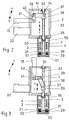
- the reference numeral 1 designates a clamping head on which coaxially one Connects housing 2, in which an electric motor with stator 3 and rotor 4 connects. With the rotor 4, a shaft 5 is connected, which via a coupling piece 6 is rotatably mounted in a roller bearing 7, which is arranged in a flange 8 is.
- the flange 8 is by several screws, not shown, over its Are arranged circumferentially distributed with the wall 9 of the clamping head arranged here 1 tight but detachable, connected.
- a bushing 10 designed as a screw nut is located in the coupling piece 6 rotatably arranged, which is provided on its inside with screw thread 11.
- This screw thread 11 corresponds to a screw thread 12 one in Longitudinal axis direction of shaft 5 in the direction X or Y of linearly drivable part 13, which is designed as a screw.
- a clamping arm 15 With the linearly drivable part 13 is over a toggle joint 14 a clamping arm 15 in the direction A or B pivotable drivable.
- the tension arm 15 is at one of its opposite end portions each with a square 16 provided shaft 5 interchangeably mounted.
- both the clamping arm 15 and a counterpart 17 have the square 16 correspondingly adapted shapes.
- the counterpart 17 is by several Screws coupled to the tension arm 15. Of these screws are only Center lines 18 and 19 illustrated in FIG. 1.
- the shaft 5 of the electric motor consisting essentially of stator 3 and rotor 4 is at its end section facing away from the rolling bearing 7 by another Rolling bearing 20 is rotatably supported in a bearing block 21.
- the bearing block 21 is in the present case formed by a housing shoulder, which is integral with the housing 2 connected is.
- a contactor is indicated at 22, while a connector for an electrical cable is indicated at 23 24 through which electrical energy can be supplied to the electric motor 3, 4.
- the end of the housing 2 is releasably closed by a bottom cover 25.
- the bottom cover 25 can be connected to the housing 2 by screws, not shown be releasably connected.
- the shaft 5 of the electric motor 3, 4 provided with a thickening 26 with which a cup-shaped Receiving element 27 is connected, which is an annular disk-shaped part 29 a permanent magnetic brake 28 receives.
- annular disk-shaped part 29 of the permanent magnet brake 28 With gap distance 31 to that annular disk-shaped part 29 of the permanent magnet brake 28 is another annular disc-shaped part 30 arranged.
- the two ring-shaped parts 29 and 30 are in a suitable manner with permanent magnetic pole pairs - north and Southern Poland - stocked. For example, on each disc, five such pairs, thus a total of ten permanent magnetic parts on each part 29 and 30 (Pole) can be provided.
- the clamping head 1 is a so-called Abutment trained jaw 32 firmly connected. Between the tension arm 15 and the jaw 32 or additionally provided contour pieces can be suitable Workpieces, for example sheets to be welded together, clamped become.
- An electric motor arranged in the housing 2 drives a threaded spindle 33 on, which is mounted at its two ends in roller bearings 34 and 35.
- a screw nut 36 is arranged, depending on the direction of rotation of the threaded spindle 33 is moved by the electric motor in the X or Y direction.
- a link 38 coupled, at the opposite end by a further pivot axis 39 is coupled to a link 40, which is about an axis 41 fixed to the housing is pivotally mounted.
- the clamping arm 15 is also in via the axis 41 Direction A or B pivoted.
- the electric motor 3 and 4 is in turn one Permanent magnetic brake 28 assigned to the tension arm in the event of a power failure 15 reliably braked with additional tools optionally arranged thereon and holds in the respective situation.
- the reference numeral 59 denotes a coupling which has a shaft 60 is geared and rotatably connected.
- the shaft 60 carries the clamping head on it 1 facing away from a receiving element 61, the annular part 29th with the permanent magnet. Is opposite with gap distance 31 again the annular part 30, also with several pairs of permanent magnets assembled.
- the arrangement and formation of the annular Parts 29 and 30 with their permanent magnet pole pairs can be the same as those described above Embodiments can be designed.
- the housing 2 also encloses the annular parts 29 and 30 of the permanent magnet brake. Stator 3 and rotor 4 are designed and arranged as in the embodiment of FIG. 1.
- the receiving element 61 can also be disc-shaped and can be made of material with the shaft 60 be designed in one piece. But it's also a functional one-piece, for example with screws, pins or split pins.
- the electric motor has a screw 42 in one or drives another direction of rotation.
- the screw 42 is at its ends in each a roller bearing 43 and 44 mounted with low friction.
- On the screw 42 is a screw nut 45 can be driven in one or the other direction of rotation.
- With the Screw nuts 45 are two links 47 and 48 via a pivot axis 46 pivotally coupled, the opposite ends at their ends Axes 49 and 50 are pivotally coupled with gripper arms 51 and 52, which also have a housing-fixed axis 53 or 54 in the direction A or B are synchronously pivotable against each other or from each other. Between themselves the grippers can grip workpieces or the like.
- a permanent magnetic brake 28 holds reliably the gripper arms 51, 52 in the respectively assumed position, even then, if there are further contour pieces or tools on it.
- the screw spindle 42 is via a coupling 62 connected to a shaft 63, which in turn has a receiving element at its end 64, which can be pot-shaped or disk-shaped and again an annular part 29 with a gap distance 31 to the annular part 30 records.
- the annular parts 29 and 30 are in turn parts of the permanent magnet brake and have a plurality or a plurality of pole pairs, that form the magnetic brake.
- the permanent magnet brake is encapsulated in the housing 2 and has even in this embodiment, no external energy supply.
- FIGS. 6 and 7 are again the same for parts Function the same reference numerals as in the pre-existing embodiments been used.
- This embodiment differs from that above-described embodiments in that the gripping arms 51 and 52 over a hollow shaft 5 are driven by the electric motor, the Pivot axis 46 or with their diametrically opposite end sections are provided with guide rollers, not shown, for example in low-friction Needle bearings can be stored.
- the guide rollers are in guide grooves in the longitudinal axis direction of the hollow shaft 5 and thus also the screw spindle 13 led.
- the guide grooves can be in the walls of the clamping head 1 be arranged. Only one of the guide grooves has the reference number 65 designated.
- the opposite guide groove has the same shape and is aligned arranged and runs parallel to the illustrated guide groove 65.
- the screw thread can also be provided by a ball screw to be replaced (not shown).
- the end stop 55 is via a screw spindle 56 from the side of the bottom cover 25 in the X or Y direction via one or more Screw nuts 57 adjustable and lockable. Instead of a nut also several nuts or additionally a lock nut can be provided to the to lock the respective setting position.
- the pivoting angle of the tensioning arm can thus be achieved via the screw spindle 56 15 set.
- the nut 57 is supported against the thickening 26 from.
- At least two spaced and dampable contactless can be in the clamping head 1
- Sensors inductive switches, limit switches, microswitches
- the sensors can be designed as an interchangeable set be and by a narrow, in the longitudinal axial direction of the clamping head 1 extending slot from the back 58 of the chuck 1 in the slot be plugged in and seal it tightly. If necessary, this can be done as a one-piece component, a set to be used against a defective set or another Exchange the set.
- the chuck 1 has suitable threaded blind holes (not shown) on, for example on both sides of the one used to hold the cassette Longitudinal slot are also provided on the back.
Landscapes
- Engineering & Computer Science (AREA)
- Mechanical Engineering (AREA)
- Power Engineering (AREA)
- Braking Arrangements (AREA)
- Mechanical Control Devices (AREA)
- Control And Safety Of Cranes (AREA)
Applications Claiming Priority (2)
| Application Number | Priority Date | Filing Date | Title |
|---|---|---|---|
| DE19931723 | 1999-07-08 | ||
| DE19931723A DE19931723C1 (de) | 1999-07-08 | 1999-07-08 | Kraftangetriebene Kniehebelspannvorrichtung zur Verwendung im Karosseriebau der Kfz-Industrie |
Publications (2)
| Publication Number | Publication Date |
|---|---|
| EP1066929A2 true EP1066929A2 (fr) | 2001-01-10 |
| EP1066929A3 EP1066929A3 (fr) | 2002-02-27 |
Family
ID=7914009
Family Applications (1)
| Application Number | Title | Priority Date | Filing Date |
|---|---|---|---|
| EP00105215A Withdrawn EP1066929A3 (fr) | 1999-07-08 | 2000-03-13 | Dispositif de serrage a genouillère motorisé avec un frein à aimant permanent |
Country Status (2)
| Country | Link |
|---|---|
| EP (1) | EP1066929A3 (fr) |
| DE (1) | DE19931723C1 (fr) |
Cited By (10)
| Publication number | Priority date | Publication date | Assignee | Title |
|---|---|---|---|---|
| FR2839914A1 (fr) * | 2002-03-08 | 2003-11-28 | Tunkers Maschb Gmbh | Dispositif de serrage pour un levier articule |
| EP1249311A3 (fr) * | 2001-04-04 | 2005-03-23 | Diro Konstruktions GmbH & Co. KG | Dispositif de serrage |
| DE102012006866A1 (de) | 2012-04-04 | 2013-10-10 | Tünkers Maschinenbau Gmbh | Kraftangetriebene Kniehebelspannvorrichtung zur Verwendung im Karosseriebau der Kfz-Industrie |
| DE102013005484B3 (de) * | 2013-03-27 | 2014-05-15 | Tünkers Maschinenbau Gmbh | Kniehebelspannvorrichtung mit Spindelantrieb |
| CN112934897A (zh) * | 2021-02-01 | 2021-06-11 | 杭州英飞创机械设备有限公司 | 制动鼓清洗治具 |
| CN113171901A (zh) * | 2021-03-24 | 2021-07-27 | 施世棋 | 一种具有夹紧功能的五金喷漆用工作台 |
| IT202000003784A1 (it) * | 2020-02-24 | 2021-08-24 | Pneumax S P A | Unita’ di attuazione del tipo a leva articolata o a camma ad azionamento elettrico |
| DE102021000171B3 (de) | 2021-01-15 | 2021-12-30 | Olaf und André Tünkers GbR (vertretungsberechtigter Gesellschafter: Dipl.-Ing. Olaf Tünkers, 40883 Ratingen) | Kniehebelspannvorrichtung mit geradliniger Spannkraft und Spindelantrieb |
| IT202300009678A1 (it) | 2023-05-15 | 2024-11-15 | Pneumax S P A | Unita’ di attuazione del tipo a leva articolata o a camma ad azionamento elettrico |
| WO2025062664A1 (fr) * | 2023-09-21 | 2025-03-27 | ニデックインスツルメンツ株式会社 | Dispositif de rotation |
Families Citing this family (7)
| Publication number | Priority date | Publication date | Assignee | Title |
|---|---|---|---|---|
| DE20018114U1 (de) * | 2000-10-23 | 2002-02-28 | DE-STA-CO Metallerzeugnisse GmbH, 61449 Steinbach | Elektrisch betätigbare Werkstück-Spannvorrichtung |
| FR2828123B1 (fr) * | 2001-07-31 | 2003-12-12 | Bema Ingenierie | Tete de bridage pour le maintien ou le serrage d'une piece |
| DE10161717B4 (de) * | 2001-12-15 | 2019-10-10 | Glw - Elektrotechnische Bauteile Kunststoffverarbeitung Gmbh | Vorrichtung zum nicht manuellen Vercrimpen |
| DE10317560A1 (de) * | 2002-04-15 | 2003-11-20 | Tox Pressotechnik Gmbh | Einspannvorrichtung |
| WO2010062235A1 (fr) * | 2008-11-25 | 2010-06-03 | Aktiebolaget Skf | Mécanisme d'accouplement pour interconnecter de façon libérable un premier et un second élément mécanique et actionneur linéaire équipé d'un tel mécanisme d'accouplement |
| DE202013007409U1 (de) | 2012-09-24 | 2013-09-17 | Tünkers Maschinenbau Gmbh | Unterbauspanner |
| CN110712145B (zh) * | 2019-10-30 | 2025-03-28 | 浙江弘迪汽车零部件有限公司 | 一种汽车刹车片与卡钳的工装夹具 |
Family Cites Families (8)
| Publication number | Priority date | Publication date | Assignee | Title |
|---|---|---|---|---|
| US4137784A (en) * | 1977-11-14 | 1979-02-06 | Industrial Device Corporation | Electromechanical equivalent of fluid powered cylinder |
| DD138643A1 (de) * | 1978-09-05 | 1979-11-14 | Gerd Ziemann | Elektromechanisch betaetigte haltevorrichtung |
| DE2931539A1 (de) * | 1979-08-03 | 1981-02-19 | Max Baermann | Schaltbare, dauermagnetische bremse fuer schienenfahrzeuge |
| JPS61154475A (ja) * | 1984-12-26 | 1986-07-14 | Japan Servo Co Ltd | 制動装置を内蔵した小形電動機 |
| DE3613644A1 (de) * | 1986-04-23 | 1987-10-29 | Josef Gerhard Tuenkers | Kraftangetriebene kniehebelspannvorrichtung |
| DE9306698U1 (de) * | 1993-05-04 | 1993-08-19 | Fritz Schunk GmbH Fabrik für Spann- und Greifwerkzeuge, 74348 Lauffen | Elektrische Dreheinheit |
| US5751127A (en) * | 1995-07-06 | 1998-05-12 | Grimes Aerospace Company | Magnet brake |
| DE19616441C1 (de) * | 1996-04-25 | 1997-06-26 | Tuenkers Maschinenbau Gmbh | Kniehebelspannvorrichtung für den Karosseriebau |
-
1999
- 1999-07-08 DE DE19931723A patent/DE19931723C1/de not_active Expired - Lifetime
-
2000
- 2000-03-13 EP EP00105215A patent/EP1066929A3/fr not_active Withdrawn
Cited By (14)
| Publication number | Priority date | Publication date | Assignee | Title |
|---|---|---|---|---|
| EP1249311A3 (fr) * | 2001-04-04 | 2005-03-23 | Diro Konstruktions GmbH & Co. KG | Dispositif de serrage |
| FR2839914A1 (fr) * | 2002-03-08 | 2003-11-28 | Tunkers Maschb Gmbh | Dispositif de serrage pour un levier articule |
| DE102012006866A1 (de) | 2012-04-04 | 2013-10-10 | Tünkers Maschinenbau Gmbh | Kraftangetriebene Kniehebelspannvorrichtung zur Verwendung im Karosseriebau der Kfz-Industrie |
| DE102012006866B4 (de) | 2012-04-04 | 2018-05-09 | Tünkers Maschinenbau Gmbh | Kraftangetriebene Kniehebelspannvorrichtung |
| DE102013005484B3 (de) * | 2013-03-27 | 2014-05-15 | Tünkers Maschinenbau Gmbh | Kniehebelspannvorrichtung mit Spindelantrieb |
| FR3003784A1 (fr) * | 2013-03-27 | 2014-10-03 | Tunkers Maschb Gmbh | Dispositif de serrage a genouillere, equipe d'un entrainement par broche |
| WO2021171189A1 (fr) * | 2020-02-24 | 2021-09-02 | Pneumax S.P.A. | Unité d'actionnement à commande électrique du type à levier articulé ou à came |
| IT202000003784A1 (it) * | 2020-02-24 | 2021-08-24 | Pneumax S P A | Unita’ di attuazione del tipo a leva articolata o a camma ad azionamento elettrico |
| DE102021000171B3 (de) | 2021-01-15 | 2021-12-30 | Olaf und André Tünkers GbR (vertretungsberechtigter Gesellschafter: Dipl.-Ing. Olaf Tünkers, 40883 Ratingen) | Kniehebelspannvorrichtung mit geradliniger Spannkraft und Spindelantrieb |
| CN112934897A (zh) * | 2021-02-01 | 2021-06-11 | 杭州英飞创机械设备有限公司 | 制动鼓清洗治具 |
| CN113171901A (zh) * | 2021-03-24 | 2021-07-27 | 施世棋 | 一种具有夹紧功能的五金喷漆用工作台 |
| IT202300009678A1 (it) | 2023-05-15 | 2024-11-15 | Pneumax S P A | Unita’ di attuazione del tipo a leva articolata o a camma ad azionamento elettrico |
| WO2024236434A1 (fr) * | 2023-05-15 | 2024-11-21 | Pneumax S.P.A. | Unité d'actionnement à entraînement électrique du type came ou levier à genouillère |
| WO2025062664A1 (fr) * | 2023-09-21 | 2025-03-27 | ニデックインスツルメンツ株式会社 | Dispositif de rotation |
Also Published As
| Publication number | Publication date |
|---|---|
| DE19931723C1 (de) | 2000-09-21 |
| EP1066929A3 (fr) | 2002-02-27 |
Similar Documents
| Publication | Publication Date | Title |
|---|---|---|
| EP1066929A2 (fr) | Dispositif de serrage a genouillère motorisé avec un frein à aimant permanent | |
| DE69321325T2 (de) | Kontaktlose leistungsübertragungsvorrichtung, kontaktlose signalübertragung, maschine mit getrennten teilen zu deren verwendung und deren regelungsverfahren | |
| DE69722957T2 (de) | Elektrischer stellantrieb | |
| EP1014031B1 (fr) | Capteur de distance avec entraînement longitudinal pour le tambour de câble de mesure | |
| DE10104669C5 (de) | Antriebskopf für NC-gesteuerte Stellbewegungen einer Werkzeugspindel oder eines Werkstücktisches um mindestens eine Drehachse | |
| EP0589935B1 (fr) | Inspection de machines dynamoelectriques effectuee dans un espace separant le stator du rotor | |
| EP1309426B1 (fr) | Dispositif de serrage a genouillere | |
| DE4314628C1 (de) | Elektrische Dreh- und Schwenkeinheit | |
| DE102013005484B3 (de) | Kniehebelspannvorrichtung mit Spindelantrieb | |
| DE2243331A1 (de) | Drehgeschwindigkeitsgeber fuer fahrzeugraeder | |
| DE3910801C2 (fr) | ||
| EP1880796B1 (fr) | Tête rotative à axes multiples pour machine-outil | |
| DE2031834A1 (de) | Elektromotorischer Regel- und Steuerantrieb mit eingebauter elektromagnetischer Scheibenkupplung und Bremse | |
| DE102013018842A1 (de) | Spannvorricntung mit zwei langhubigen Backen | |
| DE202011002899U1 (de) | Werkzeugwechsler für einen Roboterarm mit einer Drehdurchführung für Medien | |
| DE202013007409U1 (de) | Unterbauspanner | |
| DE102012006866B4 (de) | Kraftangetriebene Kniehebelspannvorrichtung | |
| DE10013612A1 (de) | Einrichtung zur Strom- und Datenübertragung an Maschinenwerkzeugen | |
| DE102010024315A1 (de) | Elektroantrieb eines linearen Zweibackenelektrogreifers | |
| DE102011015578A1 (de) | Buchsenausrichtvorrichtung für Stangenlademagazine und Verfahren | |
| WO2023202773A1 (fr) | Module linéaire, module linéaire comprenant un aimant et dispositif codeur pour déterminer la position angulaire et/ou la position d'un chariot | |
| DE20203791U1 (de) | Kniehebelspannvorrichtung | |
| AT518741B1 (de) | Arbeitskopf mit zwei Drehachsen | |
| DE102004018195B4 (de) | Kniehebelspannvorrichtung zum Spannen, Clinchen, Kleben, Schweißen oder dergleichen, vornehmlich zur Verwendung im Karosseriebau der Kfz-Industrie | |
| DE4119752A1 (de) | Einrichtung zur magnetischen befestigung von schleifscheiben in einer schleifmaschine |
Legal Events
| Date | Code | Title | Description |
|---|---|---|---|
| PUAI | Public reference made under article 153(3) epc to a published international application that has entered the european phase |
Free format text: ORIGINAL CODE: 0009012 |
|
| 17P | Request for examination filed |
Effective date: 20000404 |
|
| AK | Designated contracting states |
Kind code of ref document: A2 Designated state(s): AT BE CH CY DE DK ES FI FR GB GR IE IT LI LU MC NL PT SE Kind code of ref document: A2 Designated state(s): AT DE ES FR GB IT SE |
|
| AX | Request for extension of the european patent |
Free format text: AL;LT;LV;MK;RO;SI |
|
| PUAL | Search report despatched |
Free format text: ORIGINAL CODE: 0009013 |
|
| AK | Designated contracting states |
Kind code of ref document: A3 Designated state(s): AT BE CH CY DE DK ES FI FR GB GR IE IT LI LU MC NL PT SE |
|
| AX | Request for extension of the european patent |
Free format text: AL;LT;LV;MK;RO;SI |
|
| AKX | Designation fees paid |
Free format text: AT DE ES FR GB IT SE |
|
| 17Q | First examination report despatched |
Effective date: 20030527 |
|
| STAA | Information on the status of an ep patent application or granted ep patent |
Free format text: STATUS: THE APPLICATION HAS BEEN WITHDRAWN |
|
| 18W | Application withdrawn |
Effective date: 20031121 |