EP1066986A2 - Felge eines Fahrzeugrades für schlauchlose Luftreifen mit auf der radial äusseren Mantelfläche der Felge ausgebildeter Notlaufstützfläche - Google Patents
Felge eines Fahrzeugrades für schlauchlose Luftreifen mit auf der radial äusseren Mantelfläche der Felge ausgebildeter Notlaufstützfläche Download PDFInfo
- Publication number
- EP1066986A2 EP1066986A2 EP00112635A EP00112635A EP1066986A2 EP 1066986 A2 EP1066986 A2 EP 1066986A2 EP 00112635 A EP00112635 A EP 00112635A EP 00112635 A EP00112635 A EP 00112635A EP 1066986 A2 EP1066986 A2 EP 1066986A2
- Authority
- EP
- European Patent Office
- Prior art keywords
- rim
- bead
- features
- tire
- axially
- Prior art date
- Legal status (The legal status is an assumption and is not a legal conclusion. Google has not performed a legal analysis and makes no representation as to the accuracy of the status listed.)
- Granted
Links
- 239000005060 rubber Substances 0.000 claims abstract description 40
- 239000004033 plastic Substances 0.000 claims abstract description 22
- 239000002184 metal Substances 0.000 claims abstract description 9
- 238000000034 method Methods 0.000 claims abstract description 6
- 239000011324 bead Substances 0.000 claims description 157
- 239000000945 filler Substances 0.000 claims description 34
- 230000002787 reinforcement Effects 0.000 claims description 24
- 238000004519 manufacturing process Methods 0.000 claims description 8
- 229910000831 Steel Inorganic materials 0.000 claims description 7
- 239000010959 steel Substances 0.000 claims description 7
- 239000004753 textile Substances 0.000 claims description 5
- 239000004677 Nylon Substances 0.000 claims description 4
- 229920001778 nylon Polymers 0.000 claims description 4
- 239000004744 fabric Substances 0.000 claims description 2
- 239000002654 heat shrinkable material Substances 0.000 claims description 2
- 239000000126 substance Substances 0.000 claims 5
- 239000000463 material Substances 0.000 abstract description 22
- 230000015572 biosynthetic process Effects 0.000 description 13
- 238000005299 abrasion Methods 0.000 description 5
- 230000000694 effects Effects 0.000 description 4
- 238000009434 installation Methods 0.000 description 4
- 230000036316 preload Effects 0.000 description 4
- 230000006835 compression Effects 0.000 description 3
- 238000007906 compression Methods 0.000 description 3
- 230000008719 thickening Effects 0.000 description 3
- 238000004073 vulcanization Methods 0.000 description 3
- 230000001154 acute effect Effects 0.000 description 2
- 238000013016 damping Methods 0.000 description 2
- 238000007142 ring opening reaction Methods 0.000 description 2
- 230000035939 shock Effects 0.000 description 2
- DOSMHBDKKKMIEF-UHFFFAOYSA-N 2-[3-(diethylamino)-6-diethylazaniumylidenexanthen-9-yl]-5-[3-[3-[4-(1-methylindol-3-yl)-2,5-dioxopyrrol-3-yl]indol-1-yl]propylsulfamoyl]benzenesulfonate Chemical compound C1=CC(=[N+](CC)CC)C=C2OC3=CC(N(CC)CC)=CC=C3C(C=3C(=CC(=CC=3)S(=O)(=O)NCCCN3C4=CC=CC=C4C(C=4C(NC(=O)C=4C=4C5=CC=CC=C5N(C)C=4)=O)=C3)S([O-])(=O)=O)=C21 DOSMHBDKKKMIEF-UHFFFAOYSA-N 0.000 description 1
- 229920000271 Kevlar® Polymers 0.000 description 1
- 238000004873 anchoring Methods 0.000 description 1
- 230000006378 damage Effects 0.000 description 1
- 230000001419 dependent effect Effects 0.000 description 1
- 238000001125 extrusion Methods 0.000 description 1
- 238000002347 injection Methods 0.000 description 1
- 239000007924 injection Substances 0.000 description 1
- 238000001746 injection moulding Methods 0.000 description 1
- 239000004761 kevlar Substances 0.000 description 1
- 238000005457 optimization Methods 0.000 description 1
- 239000002984 plastic foam Substances 0.000 description 1
- 229920000728 polyester Polymers 0.000 description 1
- 230000003014 reinforcing effect Effects 0.000 description 1
- 238000005507 spraying Methods 0.000 description 1
- 238000003860 storage Methods 0.000 description 1
- 239000004636 vulcanized rubber Substances 0.000 description 1
- 238000004804 winding Methods 0.000 description 1
Images


Classifications
-
- B—PERFORMING OPERATIONS; TRANSPORTING
- B60—VEHICLES IN GENERAL
- B60B—VEHICLE WHEELS; CASTORS; AXLES FOR WHEELS OR CASTORS; INCREASING WHEEL ADHESION
- B60B21/00—Rims
- B60B21/10—Rims characterised by the form of tyre-seat or flange, e.g. corrugated
- B60B21/104—Rims characterised by the form of tyre-seat or flange, e.g. corrugated the shape of flanges
-
- B—PERFORMING OPERATIONS; TRANSPORTING
- B60—VEHICLES IN GENERAL
- B60B—VEHICLE WHEELS; CASTORS; AXLES FOR WHEELS OR CASTORS; INCREASING WHEEL ADHESION
- B60B21/00—Rims
- B60B21/02—Rims characterised by transverse section
- B60B21/021—Rims characterised by transverse section with inwardly directed flanges, i.e. the tyre-seat being reversed
-
- B—PERFORMING OPERATIONS; TRANSPORTING
- B60—VEHICLES IN GENERAL
- B60B—VEHICLE WHEELS; CASTORS; AXLES FOR WHEELS OR CASTORS; INCREASING WHEEL ADHESION
- B60B21/00—Rims
- B60B21/12—Appurtenances, e.g. lining bands
-
- B—PERFORMING OPERATIONS; TRANSPORTING
- B60—VEHICLES IN GENERAL
- B60C—VEHICLE TYRES; TYRE INFLATION; TYRE CHANGING; CONNECTING VALVES TO INFLATABLE ELASTIC BODIES IN GENERAL; DEVICES OR ARRANGEMENTS RELATED TO TYRES
- B60C15/00—Tyre beads, e.g. ply turn-up or overlap
- B60C15/02—Seating or securing beads on rims
- B60C15/0203—Seating or securing beads on rims using axially extending bead seating, i.e. the bead and the lower sidewall portion extend in the axial direction
-
- B—PERFORMING OPERATIONS; TRANSPORTING
- B60—VEHICLES IN GENERAL
- B60C—VEHICLE TYRES; TYRE INFLATION; TYRE CHANGING; CONNECTING VALVES TO INFLATABLE ELASTIC BODIES IN GENERAL; DEVICES OR ARRANGEMENTS RELATED TO TYRES
- B60C15/00—Tyre beads, e.g. ply turn-up or overlap
- B60C15/02—Seating or securing beads on rims
- B60C15/0206—Seating or securing beads on rims using inside rim bead seating, i.e. the bead being seated at a radially inner side of the rim
-
- B—PERFORMING OPERATIONS; TRANSPORTING
- B60—VEHICLES IN GENERAL
- B60C—VEHICLE TYRES; TYRE INFLATION; TYRE CHANGING; CONNECTING VALVES TO INFLATABLE ELASTIC BODIES IN GENERAL; DEVICES OR ARRANGEMENTS RELATED TO TYRES
- B60C15/00—Tyre beads, e.g. ply turn-up or overlap
- B60C15/02—Seating or securing beads on rims
- B60C15/0209—Supplementary means for securing the bead
- B60C15/0213—Supplementary means for securing the bead the bead being clamped by rings, cables, rim flanges or other parts of the rim
-
- B—PERFORMING OPERATIONS; TRANSPORTING
- B60—VEHICLES IN GENERAL
- B60C—VEHICLE TYRES; TYRE INFLATION; TYRE CHANGING; CONNECTING VALVES TO INFLATABLE ELASTIC BODIES IN GENERAL; DEVICES OR ARRANGEMENTS RELATED TO TYRES
- B60C17/00—Tyres characterised by means enabling restricted operation in damaged or deflated condition; Accessories therefor
- B60C17/04—Tyres characterised by means enabling restricted operation in damaged or deflated condition; Accessories therefor utilising additional non-inflatable supports which become load-supporting in emergency
- B60C17/06—Tyres characterised by means enabling restricted operation in damaged or deflated condition; Accessories therefor utilising additional non-inflatable supports which become load-supporting in emergency resilient
Definitions
- the invention relates to a fig of a vehicle wheel for tubeless pneumatic tires with on the radially outer circumferential surface of the rim formed emergency run support surface.
- Tubeless pneumatic vehicle tires of modern design are usually on the radially inner Ends of their side walls are formed into beads.
- a carcass formed from rubber-coated reinforcements more radially Design type.
- each tire bead there is an annular one, concentric to the tire axis arranged tensile, rigid bead core made of steel, in which the carcass is anchored.
- the pneumatic vehicle tire is used when mounting the pneumatic vehicle tire on the Fig with its bead attached to the radially outer surface of the rim.
- the tensile strength and rigidity of the bead which is determined by the tensile strength and rigidity of the Bead core ensures the desired seal in tubeless tires the fig-tire connection and ensures the tight fit of the tire on the rim in the inflated condition of the tire.
- the tensile, tensile design of the bead core prevents axial slipping even during demanding driving maneuvers Vehicle wheel from the rim over the radially outward directed rim flange.
- the tension-resistant, tension-resistant bead on a one-piece rim must be moved with its inside diameter over the larger outside diameter of the rim flange than the inside diameter of the stiff bead.
- additional effort for example the formation of the fig with a drop bed, is required.
- the tire sidewall will buckle. It can be pressed onto the rim flange designed to axially secure the pneumatic vehicle tire on the rim. If the vehicle continues to drive, the side wall of the tire and the rim flange can be destroyed. The pneumatic vehicle tire can jump off the rim.
- the executable ratio between the outside diameter of the Run-flat support surface is very limited to the inner diameter of the tensile, rigid bead.
- the outer diameter of the emergency running support surface may only be chosen so large that the stiff bead can still be moved over it.
- the emergency running support surfaces become a large part of the comparatively small inner diameter of the stiff bead and thus determined by a parameter that is insignificant for the emergency running properties. Over for optimal emergency running properties coordinated larger outer diameter of the The pneumatic tires can no longer be fitted to the emergency running surfaces of the figs.
- the high tensile strength and Pressure rigidity of the bead due to the tensile strength and pressure rigidity of the bead core ensures the desired seal in the rim-tire connection for tubeless tires and ensures the tight fit of the tire on the rim in the inflated Condition of the tire.
- the pressure-resistant, tensile design of the bead core also prevents in demanding driving maneuvers, the vehicle wheel slips axially from the Fig over the radially inward direction on the radially inner side of the rim Rim flange.
- Such a tire is known for example from DE-30 00 428 C2.
- both the fig seat and the rim flange are on the radially inner side of the rim are formed, a larger axial extension area is available for a CTS tire Formation of emergency running support surfaces on the radially outer surface of the rim Available than in the conventional on the radially outer surface of a rim attached tire-wheel system.
- the rim flange is on the radially outer side of the CTS rim no longer a rim element that disrupts emergency running.
- the tensile, pressure-resistant must Bead with its inner diameter on the radially outer surface of the rim over the compared to the inner diameter of the stiff bead larger outer diameter Run-flat support surfaces and on the radially inner surface of the rim over the opposite the inner diameter of the stiff bead smaller inner diameter are moved.
- additional effort is required, for example the formation of the rim with a Loft bed on the radially inner lateral surface as well as complex special assembly techniques, required.
- DE 19530939 C1 describes a vehicle wheel with a one-piece rim and tubeless beadless pneumatic tire known in which the radially outer surface of the rim Emergency running support surfaces is formed.
- the beadless pneumatic vehicle tire is on the radial vulcanized on the inner surface of the rim.
- the beadless training of the Pneumatic vehicle tire allows the formation of such a tire Emergency running support surfaces regardless of bead diameters.
- To train the Run-flat support surfaces can be important for emergency running in such a pneumatic vehicle tire Parameters are better taken into account, so that also for emergency running property optimization desired larger diameter of the emergency support surfaces can be easily realized.
- such pneumatic vehicle tires cannot be easily dismantled without being destroyed or be changed.
- the invention has for its object to provide the emergency running surface of a vehicle wheel for tubeless pneumatic tires in a simple and reliable.
- the object is achieved by the formation of a rim according to the features of claim 1, as well as by the design of a vehicle wheel according to the features of claim 10 or by the method according to the features of claim 21.
- the emergency running support surface can be very easily in the plastically deformable state positioned exactly on the supporting surface and through during vulcanization Vulcanization to the supporting surface can be securely fixed in this position so that the emergency running support surface is also very safe during operation in emergency running maintains precisely defined position on the rim.
- the training according to the features of claim 2 or 22 grants a Run-flat support surface with higher strength. That is particularly advantageous with a bandage effect Training according to the features of claim 3 or 23.
- the strength members are preferably designed according to the features of claim 4.
- The are preferred Reinforcements made of nylon or another suitable heat-shrinkable Material formed that shrinks due to the action of heat during vulcanization and thereby builds up preload.
- the training according to the features of claim 5 makes it easy to ensure that the emergency running support surface is particularly reliable also counteracting the centrifugal forces occurring at high operating speeds certainly keeps its shape.
- the training according to claim 6 enables in a simple manner the mechanically uniform production with simultaneous use of a minimal number of when placing ends of reinforcements to be secured. This is particularly advantageous Training according to the features of claim 7.
- a particularly advantageous embodiment of a vehicle wheel is the embodiment according to the features of claim 11.
- the bead is inserted axially into the annular chamber through the through opening.
- the filler ring is inserted axially into the annular chamber radially inside the bead.
- the bead is then fixed radially in the annular chamber on the radial outside of the filler ring and is formed positively radially outward, axially inward and axially outward to the annular chamber, so that the bead is radially outward, axially outward, axially inward and over the Filling ring positively connected radially inward to the one-piece annular chamber.
- An embodiment is preferred in which the bead in the annular chamber also in the axial direction has inward positive engagement with the axially inner annular chamber wall, so that the position of the bead in the annular chamber by positive locking in the axial direction axially inwards axially inner ring chamber wall - in individual cases not to be ruled out stronger axially inward forces introduced into the bead defined can be maintained.
- the filler ring is preferably cylindrical on its radially outer surface. This enables particularly simple and reliable assembly and disassembly of the Pneumatic vehicle tire on the rim.
- the bead After the bead is in its fastening position in the Annular chamber has been introduced, it is simply moved axially Filling ring on the bearing surface of the annular chamber designed for this purpose in its filling position in pushed the annular chamber, whereby the positive engagement of the bead in the annular chamber is manufactured and secured.
- the cylindrical Training also ensures that there is a risk of accidental Release of the filler ring from the ring chamber due to undesired axial introduction Forces from the tire bead in the filler ring is reliably minimized.
- Circumferential length - especially elastic - changeable bead core enables assembly of the bead by moving over the emergency running surface with a larger one Bead core diameter than in the attached operating state of the bead and for movement over the rim flange with a smaller bead core diameter than in the fixed one Operating state, so that the formation of the emergency support surfaces is no longer dependent on the diameter of the bead core in the operating state and on the inside Rim flange diameter, but primarily optimal emergency running properties can be trained accordingly.
- the bead which can be changed in its circumferential length can be both assembled and disassembled in a simple and reliable manner be, whereby both the emergency running support surfaces for the emergency running are optimized as well Rim flange with regard to the axial support for the bead and the bead core in its Operating state can be optimized in terms of its properties in the operating state can.
- the pneumatic vehicle tire with an elastically variable circumferential length of the Beading is particularly simple and safe to change the circumferential length from a first one Circumferential length to be changed individually according to the respective requirements further circumferential lengths against the effect of restoring forces and back in the first circumferential length can be achieved using the restoring forces.
- the training according to the features of claim 13 is preferred for achieving Particularly good emergency running properties, since the tread despite the optimal clearance width that between the tire beads of the pneumatic vehicle tire, especially in the particularly critical ones Shoulder areas can be adequately supported. It is particularly advantageous to Support of the shoulder areas that are particularly critical in emergency running on the axial Side areas of the radially outer circumferential surface of the rim each have an emergency running support surface to train.
- a particularly advantageous embodiment of the vehicle wheel is one in which the bead core Bead is integrated trained rubber core.
- the rubber core is easy to manufacture and can be anchored particularly easily and reliably in the bead.
- the bead can hereby elastically extensible in its circumferential length in a simple, reliable manner be formed.
- the rubber core with a Shore A hardness in the range from 80 to 100, preferably in the range between 85 to 90.
- the bead is completely coreless educated.
- the bead is particularly simple without additional effort for a core Manufacturing is sufficient due to its coreless rubber material in its circumferential length train elastically stretchable and can still be safely and reliably through the Form fit to be anchored in the ring chamber.
- the vehicle wheel is preferably designed such that the axially outer end face as one axial support surface for the axial support of the lower tire side wall is formed.
- the tire can be achieved when cornering in the lower side wall area good handling properties supported axially and can withstand special shock loads Abolition of the axial support effect down to the lower side wall area to achieve this with good comfort properties.
- Inner ring diameter of the bead core when the vehicle wheel is assembled enables optimum emergency running properties due to the particularly large outer diameter of the Run-flat support surfaces while maintaining the tire to achieve good deflection and thus good comfort properties, optimal small inner ring diameter of the bead core.
- the formation of a vehicle wheel in which the largest outer diameter of the Emergency running surfaces larger by a factor between 1.1 and 1.2 Inner ring diameter of the bead core when the vehicle wheel is assembled provides an optimal training area for the standard tire dimensions to solve the Conflicts of goals between good emergency running properties on the one hand and comfort and weight of the Vehicle wheel on the other hand.
- the formation of a vehicle wheel in which the bead core has an extensibility and / or Compressibility of 5 to 30% enables simple and reliable installation despite optimal emergency running properties by training particularly large Outside diameter of the emergency support surfaces despite maintaining the achievement of the achievement good tire deflection and thus good comfort properties thanks to the optimally small size Inner ring diameter of the bead core.
- the bead is in each case on the for assembly or Disassembly over the emergency running surfaces required optimal diameter to the Assembly or disassembly required using the inward-facing rim flange optimal diameter and on the necessary for a secure fit in the ring chamber optimal diameter set.
- Bead core has an extensibility of 5 to 30% and a compressibility of 1 to 5% and after that the bead core, in particular in the assembled state of the vehicle wheel is unstretched and undersized.
- the bead core is mounted on one for assembly or disassembly brought over the emergency running surface optimally large diameter.
- By simple - especially elastic - compression from the unstretched and uncompressed Condition is the bead core on one for assembly or disassembly over the inside directed rim flange optimally brought small diameter.
- the bead core in the assembled Condition of the vehicle wheel is unstretched and un-compressed and thus in the circumferential direction is largely free of circumferential internal forces.
- the elastic, stretchable and elastically compressible design is particularly advantageous. The bead core will from the unstretched and non-compressed state for assembly via the Emergency running support surfaces counteract the elastic restoring forces in the circumferential direction stretched.
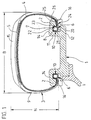
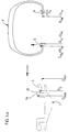
- Fig. 1 shows a vehicle wheel with pneumatic vehicle tires 3 and rim 1 with a ratio of maximum height H to maximum width 8 of the pneumatic vehicle tire H / W ⁇ 0.6.
- the Pneumatic vehicle tire 3 has a circumference of the tire and from the left bead area 6 of the pneumatic vehicle tire reaching to the right bead area 6, not shown in detail, Inner layer over which a carcass 4 radial design with, for example, one or two carcass plies is built up.
- the area of the tread is radially outside of the Carcass 4 a belt 5 of known type with, for example, two belt plies made in Rubber-embedded reinforcement, e.g. made of steel cord.
- the belt is enough over the entire circumference of the tire and extends in the axial direction from one tire shoulder area in the other.
- the steel cords run at an acute angle of, for example, 10-30 ° to the circumferential direction. Radially outside the belt layers, it is conceivable to have a belt bandage, not shown strength members running essentially to the circumferential direction, for example made of Nylon to wind up.
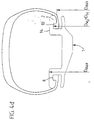
- the one-piece fig 1 is provided with one on each of its two axial end faces Arranged concentrically to the fig annular chamber 10 with a radially inner Annular chamber wall 20, an axially inner annular chamber wall 21, a radially outer one Annular chamber wall 22 and an axially outer annular chamber wall 23 are formed in one piece.
- the annular chamber wall 23 delimits the radially inwardly directed rim flange 2. Axially to the inside between the rim flange 2 and the radially inner annular chamber wall 20 is one annular through opening 24 formed axially from the outside towards the annular chamber.
- the Rim flange 2 is on its radially inward side 25 from axially inward to axially flared on the outside and curved on its end face 26.
- On the radial outer side of the rim flange extends an emergency saddle 11 with his Run-flat saddle surface 14 axially inward beyond the position of the annular chamber 10.
- Each surface of the emergency saddle extends axially inwards so far that the belt is in its axial edge zones from the shoulder each with 10 to 30%, for example 25%, axially is covered.
- the vehicle pneumatic tire 3 engages with its lower side wall regions 16 horns 2 extending radially inward.
- the curvature of the end face 6 of the horn corresponds to that desired tire contour in the area of the horn.
- the bead area 6 is in each case with The bulge-shaped thickening 7 formed on the inside of the tire.
- the bead is with an elastic stretchy and elastic embedded in the carcass ply end compressible core 8 formed.
- the bead area fills 6 with positive locking to the axially inner annular chamber wall 21 and the radially outer Annulus 22 and the axially outer annulus 23 about 1/2 to 2/3 of Annulus.
- a filler ring 12 is radially form-fitting radially inside the bead to the bead area 6 radially outwards and radially inwards to the radially inner one Ring chamber warid 20 is formed, which extends in the axial direction from the ring chamber wall 10 over the entire axial extent of the bead region 6 through the ring opening 24 extends axially outward therethrough.
- the filler ring 12 is over the entire axial Extension area of the annular chamber and thus of the bead on its radially outer Shell cylindrical and axially outside the annular chamber parallel to the radially inner Side of the rim flange 25 flared.
- the filler ring 12 extends in the axial direction up to the axial position of the end face 26 of the rim flange.
- the bead is in the embodiment according to FIG. 1 with positive locking radially outward, axially inward and axially outward to the closed Annular chamber walls 22, 23, 21 and through the radial positive connection to the filler ring 12, the is in turn designed in a radial positive connection to the closed annular chamber wall 20, also to the annular chamber wall 20 in radial positive engagement.
- the annular chamber is completely filled with bead and filler ring.
- the lower side wall region 16 stands with the radially inner conical one Rim flange side 25 and with the correspondingly designed conical outer Mantle surface of the filler ring 12 also in the axial extent of the rim flange in full contact.
- the tire side wall lies in the region of the end face 26 of the horn 2 of the rim only under tension.
- the side wall area available for this purpose for the flexible curvature of the side wall extends from the shoulder area of the tread to the entire curved area of the end face 26. In the event of strong impacts, the tire side wall 9 lifts off in the area of the end face 26, forming a gap between the end face 26 and the tire side wall .
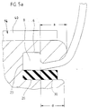
- the axially inward-running emergency saddle 11 extends over the entire Circumferential area of the tire and, as shown in Fig. 5a, with an over the Provide circumferentially extending emergency running support layer 40.
- the tire With sudden loss of internal pressure the tire supports itself with its tread area on the mutually provided essentially cylindrical or axially inward with a slightly tapered surface with a slope angle of 0 to 10 ° to the axis direction of the emergency running support layer 40 of the emergency saddle 11. Early destruction and detachment of the tire avoided.
- the emergency running support layer 40 is made of hard plastic, rubber or plastic foam trained who is insensitive to shock for damping and the good Has sliding properties for emergency running.
- 5b shows an embodiment of such an emergency running support layer 40, in the additional embedded thread-like or ribbon-like reinforcements are.
- these reinforcements are monofilaments or Multifilaments of textile type - for example made of nylon, kevlar, polyester - or steel. she extend over the circumference of the fig and are at an angle of 0 to 30 ° to Aligned circumferential direction of the rim.
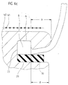
- FIG. 6a to d shows the production of the emergency running support layer 40 on the emergency running saddle metallic rim.
- a layer 40 ′ becomes plastic deformable, unvulcanized rubber or plastic material in the operating position the emergency support surface on the emergency saddle.
- the layer 40 'of plastically deformable, unvulcanized rubber or Vulcanized plastic material If the layer 40 'of plastically deformable, unvulcanized rubber or Vulcanized plastic material.
- the fully vulcanized layer 40 'of cushioning rubber - or plastic material forms the emergency running support surface 40, which is important for emergency running.
- the strength members - for example metallic or textile monofilaments or Known multifilament - become equidistant from each other or as far as different Strength gradients of the emergency running support surface are desired with these strength gradients corresponding distance differences. They extend at least over the entire circumference of the rim at an angle of 0 to 30 ° to the circumferential direction of the Rim. It is also possible to use one or more reinforcements, for example metallic or textile monofilaments or multifilaments of a known type - continuously helical over the circumference of the rim from one axial side to the other axial side with an acute angle of 0 to 30 ° to the circumferential direction of the Fig.
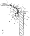
- FIG. 2a shows an enlarged detailed view of the outer edge region of the rim of FIG Fig. 1.
- Figure 2a it can be seen that the inside 25 of the rim flange of the Annular chamber wall 23 starting from the inclusion of an angle ⁇ to the wheel axis axially externally expanded up to the curved end face 26 of the rim flange 2.
- the radial outer lateral surface of the filling ring 12 is starting from the annular chamber wall 21 over the entire axial extent of the annular chamber to the annular chamber wall 23 and in an axial extension from the annular chamber up to an axial distance b
- Annular chamber wall 23 is cylindrical.
- the radially outer surface of the filler ring 12 is axial Direction to the outside parallel to the inside 25 of the rim flange also included of the angle ⁇ to the wheel axis axially outwardly flared.
- the Filling ring like the rim flange, still extends a distance a from Annular chamber wall 23 axially outwards.
- the filler ring 12 is axially displaceable on a cylindrical bearing surface 30 of the fig. Inside the ring chamber forms the Bearing surface 30, the radially inner annular chamber wall 20. The extends axially outward Bearing surface 30 to a distance d from the annular chamber wall 23.
- Axially outside of Distance d is the filler ring thickened radially inward to a shoulder and lies with this on a correspondingly trained shoulder of the rim.
- the distances a, b, d are chosen such that a is greater than d and d is greater than b.
- the angle ⁇ lies between 2 and 20 °. In the illustrated embodiment, it is approximately 10 °. In this way enclose the bead with its thickening 7 and the subsequent lower one Sidewall region 16 between the inner rim flange 25 and the filler ring the rim flange positively guided, whereby the anchoring of the tire in the rim is additionally secured.
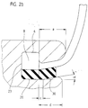
- the filler ring is made of rubber or an elastic plastic with self-locking Surface trained. It is also conceivable to make the filler ring from a non-elastic Manufacture plastic or metal. If necessary in individual cases, it is also possible to Filling ring in the assembled state with its shoulder on the corresponding shoulder of the For example, additionally fix figs axially by spraying.
- the Bearing surface 30 extends axially to a distance c, which is less than or equal to that Distance a is from the annular chamber side wall 23 to the outside.
- the radially outer The lateral surface of the filling ring is from the axial position of the ring chamber side wall 23 also conical at the pitch angle ⁇ .
- the radial interior The outer surface of the filler ring is just like the correspondingly designed bearing surface 30 from an axial position at a distance c from the ring chamber side wall to the outside axially also conically expanded at an angle ⁇ to the wheel axis.
- the distance is c smaller a. Due to this conical design, the elastic filling ring is mounted in its Position additionally secured by axial positive locking.
- Fig2c is a filling ring as shown in Fig2b, but in the elastic rubber or Plastic material embedded essentially extending in the circumferential direction
- Strength member 17 contains.
- the strength members give the filler ring additional hold of the bearing surface 30.
- the strength members 17 can be arranged in a number of side by side Be circumferential wound tensile strength members.
- Another version is one or more strength members arranged side by side continuously helical around the axis of the filler ring from one axial end to the other axial end of the filler ring wrapped.
- the distances between the adjacent windings are equidistant. So far useful to achieve an even more secure fixation of the filling ring on the bearing surface 30, the distances can also be chosen differently.
- the strength members are Monofilaments or multifilaments made of steel. In another version they are Reinforcing textile monofilaments or multifilaments. It is also conceivable that To form reinforcement 17 from strips of fabric. The reinforcement of the filler ring 12 by strength members in the manner described is also in the embodiment of Fig.2a possible.
- FIG. 2d shows a filling ring which is cylindrical over its entire axial extent has radially outer lateral surface.
- the radially inner lateral surface is also in the essentially cylindrical.
- the filler ring can also be used in this case as for the above Described embodiments - with or without reinforcement.
- the bead core 8 is made by embedding the core 8 into the carcass 4 by turning the carcass 4 around the core from the inside out, or as shown in the embodiment of Fig. 3b, anchored from the outside inwards.
- the Carcass 4 is tightly wrapped around core 8 and the cover 4 'is the same as in the other Embodiment of the envelope 4 '' following the core 8 in direct contact to the main part of the carcass.
- the core 8 is droplet-shaped to the point of contact between Cover and body of the carcass are tapered.
- To form the core 8 is an elastic rubber material with a Shore A hardness of 80 to 100, preferably 85 to 90 - in the exemplary embodiment of FIG.
- the core is extrusion by injection molding or comparatively known Techniques made.
- the rubber material of the bead is chosen so that the bead has the stated elongation and compression properties in the circumferential direction having.
- abrasion-resistant material for example of to form abrasion-resistant rubber or plastic.
- the abrasion-resistant strip can go right into the Ring chamber and be folded over there around the bead.
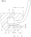
- the emergency running support surfaces 14 have one maximum outer diameter Dmax, the two rim flanges a minimum Inner diameter Dmin.
- the tire bead is in Fig.4a in the unexpanded and un-compressed state.
- Its outer diameter Dwa corresponds to the diameter of the radially outer annular chamber wall 22 and thus the outer diameter of the bead Dsa in its sitting position in the ring chamber.
- Its inner diameter Dwi corresponds to that Diameter of the radially outer circumferential surface of the filling ring 12 in the annular chamber and thus the inner diameter of the bead Dsi in its seating position in the annular chamber.
- Dmax is greater than Dsa
- Dsa is greater than Dsk
- Dsk is greater than Dmin
- Dmin is greater than Dsi.
- the tire 3 is concentric with the rim on the rim in the figures of right axially brought up.
- the left bead is counter to the elastic restoring forces of the Bead stretched in the circumferential direction so far that the inner diameter Dwi of the bead is larger than the maximum outer diameter Dmax of the emergency running support surfaces.
- the tire 3 further concentric to the rim axially to the rim moves, with the left bead while maintaining its stretched state with play is pushed axially over the rim to the emergency running support surfaces 14.
- the beads are axially into the with play to the fig horn respective ring chamber introduced.
- the beads are set back in their circumferential length so far that they again assume unstretched and uncompressed state, in this state corresponds to Dwi again Dsi, Dwa again Dsa and Dwk also correspond to the middle one again Diameter Dsk of the core in its seating position in the ring chamber.
- the beads sit unstretched and undersized in the ring chamber. This state is shown in Fig.4d. As shown in FIG.
- a filler ring 12 is now between each axially outside lower sidewall region 16 of the tire and bearing surface 30 axially inserted so far that the annular chamber is completely filled by the bead and filler ring.
- the complete one Form-fit between the one-piece annular chamber and the bead is established.
- the filling ring is first removed axially outwards. After that the beads are compressed so far that they play with the rim flange from the ring chamber can be pulled. After resetting the circumferential length, a bead becomes so far stretched that it can be pulled axially from the rim with play to the emergency running support surfaces can.
- the diameter Dmax is, for example, 1.2 times larger than the inside diameter Dsi of the bead in the sitting position in the annular chamber and the minimum rim flange diameter is 1.025 times smaller than that Outside diameter Dsa of the bead in the sitting position in the ring chamber.
- Rubber material of the bead becomes a rubber material with an elasticity and with a compressibility chosen, such a stretching and compressing the bead in Circumferential direction allow the bead over the emergency support surface 14 and in the Annular chamber can be moved axially with play.
- a well-known Rubber material is used, the circumferential expansion of the bead by 25% and one Enable circumferential compression by 2.7%.
- the emergency support surfaces can also have a larger or smaller maximum Outside diameter Dmax according to the individually to be set Run-flat properties of a tire.
- the maximum diameter Dmax Run-flat support surfaces are ideally a factor of 1.1 to 1.2 for standard tires larger than the inner ring diameter Dsi of the bead core when the Vehicle wheel. In special cases, however, it can also be by a factor between 1.05 and 1.3 larger than the inner ring diameter Dsi of the bead core in the assembled state of the vehicle wheel.
- a rubber material is used as the rubber material of the bead with an extensibility and with a compressibility chosen, such an elongation and circumferentially upsetting the bead allow the bead to pass over the Emergency running support surface 14 and can be moved axially with play in the annular chamber.
- the bead which is not stretched when the vehicle wheel is assembled and is not compressed, designed such that it has an extensibility between 10 and 20% and a compressibility of 2.5 to 3.5% for standard tires and one in special cases Elasticity between 5 and 30% and compressibility between 1 and 5% having.
- This emergency running support surface can also be used according to the description for the representation of Fig.5 or Fig6 are produced.
- This emergency running support surface can, for example, via the entire axial belt width of the tire.
Landscapes
- Engineering & Computer Science (AREA)
- Mechanical Engineering (AREA)
- Tires In General (AREA)
- Heating, Cooling, Or Curing Plastics Or The Like In General (AREA)
- Moulds For Moulding Plastics Or The Like (AREA)
Abstract
Description
Im Falle des Luftdruckverlustes knickt die Reifenseitenwand ein. Dabei kann sie auf das zur axialen Sicherung des Fahrzeugluftreifens auf der Felge ausgebildete Felgenhorn gepreßt werden. Bei Weiterfahrt des Fahrzeugs kann die Reifenseitenwand und das Felgenhorn zerstört werden. Der Fahrzeugluftreifen kann von der Felge springen.
Die Aufgabe wird erfindungsgemäß durch die Ausbildung einer Felge gemäß den Merkmalen des Anspruchs 1, sowie durch die Ausbildung eines Fahrzeugrades gemäß den Merkmalen von Anspruch 10 oder durch das Verfahren gemäß den Merkmalen von Anspruch 21 gelöst.
Während des Fahrzeugradbetriebes besteht sowohl im Normal- als auch im Notlaufbetrieb nach Druckluftverlust ein sicherer Formschluß nach axial außen und innen und nach radial außen und innen zwischen einstückiger Ringkammer der Felge und Wulst. Sowohl die axialen als auch die radial auf den Wulst wirkenden Kräfte werden somit sicher in die im Befestigungsbereich einstückige Felge eingeleitet. Auf diese Weise kann der Wulst sogar im Notlaufbetrieb sicher und zuverlässig seine Betriebsposition in der Ringkammer beibehalten.
- Fig. 1
- eine Querschnittsdarstellung eines erfindungsgemäßen Fahrzeugrades mit montiertem Fahrzeugreifen,
- Fig. 2
- Querschnittsdarstellungen von Ausführungsformen des Füllrings,
- Fig. 3
- Querschnittsdarstellungen von Ausführungsformen des Wulstbereichs,
- Fig.4
- schematische Darstellung zur Erläuterung der Montage und der Demontage,
- Fig.5
- Darstellung der Notlaufstützfläche und
- Fig.6
- schematische Darstellung zur Erläuterung der Herstellung der Notlaufstützfläche.
- 1
- Felge
- 2
- Felgenhorn
- 3
- Fahrzeugluftreifen
- 4
- Karkasse
- 5
- Gürtel
- 6
- Wulstbereich
- 7
- Verdickung
- 8
- Kern
- 9
- Seitenwand
- 10
- Ringkammer
- 11
- Notlaufsattel
- 12
- Füllring
- 13
- Abriebfester Streifen
- 14
- Notlaufsatteloberfläche
- 15
- Lauffläche
- 16
- unterer Seitenwandbereich
- 17
- Festigkeitsträger
- 20
- Ringkammerwand
- 21
- Ringkammerwand
- 22
- Ringkammerwand
- 23
- Ringkammerwand
- 24
- Ringöffnung
- 25
- Innenseite des Felgenhorns
- 26
- Stirnfläche des Felgenhorns
- 30
- Lagerfläche
- 40
- Notlaufstützschicht
- 41
- Festigkeitsträger
Claims (23)
- Feige eines Fahrzeugrades für schlauchlose Luftreifen mit auf der radial äußeren Mantelfläche der Felge ausgebildeter Notlaufstüzfläche,wobei die Notlaufstützfläche aus einer auf eine tragende Metallstruktur aufvulkanisierten ringförmigen Schicht aus Gummi, gummiähnlichen Stoffen oder Kunststoff ausgebildet ist.
- Feige gemäß den Merkmalen von Anspruch 1,wobei Festigkeitsträger in der Schicht aus Gummi Festigkeitsträger angeordnet sind.
- Felge gemäß den Merkmalen von Anspruch 2,wobei die Festigkeitsträger faden- oder bandförmige Festigkeitsträger sind.
- Felge gemäß den Merkmalen von Anspruch 3,wobei die Festigkeitsträger Monofilamente oder Multifilamente - insbesondere textiler Art oder Stahl - sind,wobei die Festigkeitsträger vorzugsweise aus.Nylon oder einem anderen wärmeschrumpffähigen Material ausgebildet sind.
- Felge gemäß den Merkmalen von Anspruch 3 oder 4,wobei die Festigkeitsträger wenigstens eine Lage von parallel zueinander angeordneten Festigkeitsträgern aufweisen, die insbesondere sich über den Umfang der Felge erstrecken und mit einem Winkel von 0 bis 30° zur Umfangsrichtung der Felge ausgerichtet sind.
- Felge gemäß den Merkmalen von Anspruch 5,wobei die Festigkeitsträger einen oder mehrere kontinuierlich sich über den Umfang der Felge erstreckenden wendelförmig mit einem Winkel von 0 bis 30 ° zur Umfangsrichtung der Felge gewickelten Festigkeitsträger aufweisen.
- Felge gemäß den Merkmalen von einem oder mehreren der vorangegangenen Ansprüche,wobei die Felge selbst die tragende Metallstruktur bildet.
- Felge gemäß den Merkmalen von Anspruch 7,wobei die Felge einstückig ausgebildet ist.
- Felge gemäß den Merkmalen von einem oder mehreren der vorangegangen Ansprüche,mit wenigstens in einer axialen Stirnseite der Felge zur Aufnahme des Reifenwulstes zur Befestigung des Reifens auf der Felge einstückig ausgebildeter Ringkammer mit einer radial inneren,einer radial äußeren, einer axial zur Felgenmitte hin inneren und einer axial zur Felgenaußenseite hin äußeren Ringkammerwand, die nach axial außen zur Stirnseite der Felge hin im radial äußeren Bereich als ein radial nach innen gerichtetes Felgenhorn ausgebildet und in ihrem radial inneren Bereich mit einer ringförmigen Durchgangsöffnung zum Einführen bzw Ausführen des Reifenwulstes ausgebildet ist.
- Fahrzeugrad mit - insbesondere einteiliger - Felge und schlauchlosem Luftreifen, das für Notlauf geeignet ist,
wobei die Felge gemäß den Merkmalen von einem oder mehreren der vorangegangenen Ansprüche ausgebildet ist. - Fahrzeugrad gemäß den Merkmalen von Anspruch 10,mit auf der radial äußeren Mantelfläche der Felge ausgebildeter Notlaufstützflächemit an jeder Seitenwand des Luftreifens zur Innenseite des Luftreifens hin verdickt ausgebildetem Wulst zur Befestigung des Luftreifens an der Felge,mit wenigstens in einer axialen Stirnseite der Felge einstückig ausgebildeter Ringkammer mit einer radial inneren,einer radial äußeren, einer axial zur Felgenmitte hin inneren und einer axial zur Felgenaußenseite hin äußeren Ringkammerwand, die nach axial außen zur Stirnseite der Felge hin im radial äußeren Bereich als ein radial nach innen gerichtetes Felgenhorn ausgebildet und in ihrem radial inneren Bereich mit einer ringförmigen Durchgangsöffnung ausgebildet ist,wobei ein Füllring innerhalb der Ringkammer auf der radial inneren Ringkammerwand formschlüssig radial fest gelagert ist,wobei die Seitenwand des Reifens sich zumindest im Betriebszustand des Fahrzeugrades von axial außen durch die Öffnung in der axial außen ausgebildeten Ringkammerwand hindurch nach innen erstreckt und der Wulst in der Ringkammer auf der radialen Außenseite des Füllrings radial fest gelagert ist und formschlüssig zumindest nach radial außen und nach axial außen zur Ringkammer ausgebildet ist, sodaß der Wulst nach radial außen, nach axial außen, nach axial innen und über den Füllring nach radial innen formschlüssig mit der Felge verbunden ist,wobei der Wulst insbesondere über seine ganze axiale Erstreckung nach radial innen vollständig auf dem Füllring aufliegt.
- Fahrzeugrad gemäß den Merkmalen von Anspruch 10 oder 11,wobei der Wulst zur Befestigung des Luftreifens an der Felge in seiner Umfangslänge - insbesondere elastisch - veränderbar ausgebildet ist.
- Fahrzeugrad gemäß den Merkmalen von einem oder mehreren der vorangegangenen Ansprüche,
wobei die axiale Position einer in der radial äußeren Mantelfläche ausgebildeten Notlaufstützfläche zumindest teilweise der axialen Position des in der Felge befestigten Wulstes entspricht. - Fahrzeugrad gemäß den Merkmalen von einem oder mehreren der vorangegangenen Ansprüche,
wobei auf wenigstens einem axialen Seitenbereich der radial äußeren Mantelfläche der Felge eine Notlaufstützfläche ausgebildet ist, die sich insbesondere axial soweit nach innen erstreckt, daß der Gürtel in seiner axialen Randzonen von der Schulter mit 10 bis 30 % überdeckt ist. - Fahrzeugrad gemäß den Merkmalen von einem oder mehreren der vorangegangenen Ansprüche,
wobei im Wulst ein Gummikern integriert ausgebildet ist,
wobei der Gummikern insbesondere mit einer Shore -A- Härte aus dem Bereich von 80 bis 100, bevorzugt aus dem Bereich zwischen 85 bis 90 ausgebildet ist. - Fahrzeugrad gemäß den Merkmalen von einem oder mehreren der vorangegangenen Ansprüche,
wobei der Füllririg zum Lösen und/oder zum Befestigen des Wulstes axial bewegbar ausgebildet ist,
wobei die Ringkammer an ihrer radial inneren Seite über ihre gesamte axiale Erstreckung als Lagerfläche zum axialen Aufschieben und zum axialen Abziehen des Füllrings ausgebildet ist und
wobei der Füllring an seiner radial inneren Seite als korrespondierende Lagerfläche ausgebildet ist. - Fahrzeugrad gemäß den Merkmalen von einem der vorangegangenen Ansprüche, bei dem der maximale Durchmesser der Notlaufstützflächen um einen Faktor zwischen 1,05 und 1,3 - insbesondere zwischen 1,1 und 1,2 - größer als der Innenringdurchmesser des Wulstkerns im montierten Zustand des Fahrzeugrades beträgt.
- Fahrzeugrad gemäß den Merkmalen von einem der vorangegangenen Ansprüche, wobei der Wulstkern eine Dehnbarkeit und/oder Stauchbarkeit von 5 bis 30 % - insbesondere 10 bis 20 % - aufweist.
- Fahrzeugrad gemäß den Merkmalen von einem der vorangegangenen Ansprüche, wobei der Wulstkern eine Dehnbarkeit von 5 bis 30 % -insbesondere 10 bis 20 % - und eine Stauchbarkeit von 1 bis 5% - insbesondere von 2,5 bis 3,5 % - aufweist und wobei der Wulstkern insbesondere im montierten Zustand des Fahrzeugrades ungedehnt und ungestaucht ist.
- Fahrzeugrad gemäß den Merkmalen von einem der vorangegangenen Ansprüche, wobei der Luftreifen mit seinem Wulst an der Felge befestigt ist und im unteren Seitenwandbereich an der Felge anliegt.
- Verfahren zur Herstellung einer Felge mit Notlaufstützfläche gemäß Anspruch 1,wobei die Notlaufstützfläche dadurch hergestellt wird, daß auf eine tragende Metallstruktur eine ringförmige Schicht aus kautschuk- oder kautschukähnlichen Stoffen oder Kunststoff aufgebaut wird und anschließend vulkanisiert wird, wodurch die ringförmige Schicht an der tragenden Metallstruktur anvulkanisiert.
- Verfahren gemäß den Merkmalen von Anspruch 21,
wobei nach Aufbringen einer ersten ringförmigen Schicht aus kautschuk- oder kautschukähnlichen Stoffen oder Kunststoff zunächst auf diese Schicht Festigkeitsträger aufgelegt werden und dann auf diese Schicht Festigkeitsträger eine weitere Schicht aus kautschuk- oder kautschukähnlichen Stoffen oder Kunststoff aufgelegt wird, und wobei anschließend der Kautschuk- oder Kautschukähnliche Stoff oder Kunststoff vulkanisiert wird, wodurch die ringförmige Schicht an der tragenden Metallstruktur anvulkanisiert. - Verfahren gemäß den Merkmalen von Anspruch 22,
wobei die Festigkeitsträger fadenförmige oder bandförmige Festigkeitsträger sind, die auf die erste ringförmigen Schicht aus kautschuk- oder kautschukähnlichen Stoffen oder Kunststoff zunächst auf diese Schicht Festigkeitsträger aufgewickelt werden.
Applications Claiming Priority (2)
| Application Number | Priority Date | Filing Date | Title |
|---|---|---|---|
| DE19930939A DE19930939A1 (de) | 1999-07-05 | 1999-07-05 | Felge eines Fahrzeugrades für schlauchlose Luftreifen mit auf der radial äußeren Mantelfläche der Felge ausgebildeter Notlaufstützfläche |
| DE19930939 | 1999-07-05 |
Publications (3)
| Publication Number | Publication Date |
|---|---|
| EP1066986A2 true EP1066986A2 (de) | 2001-01-10 |
| EP1066986A3 EP1066986A3 (de) | 2004-04-21 |
| EP1066986B1 EP1066986B1 (de) | 2007-01-03 |
Family
ID=7913686
Family Applications (1)
| Application Number | Title | Priority Date | Filing Date |
|---|---|---|---|
| EP00112635A Expired - Lifetime EP1066986B1 (de) | 1999-07-05 | 2000-06-15 | Felge eines Fahrzeugrades für schlauchlose Luftreifen mit auf der radial äusseren Mantelfläche der Felge ausgebildeter Notlaufstützfläche |
Country Status (3)
| Country | Link |
|---|---|
| US (1) | US6523589B1 (de) |
| EP (1) | EP1066986B1 (de) |
| DE (2) | DE19930939A1 (de) |
Citations (2)
| Publication number | Priority date | Publication date | Assignee | Title |
|---|---|---|---|---|
| DE3000428C2 (de) | 1980-01-08 | 1988-04-14 | Continental Gummi-Werke Ag, 3000 Hannover | Fahrzeugrad |
| DE19530939C1 (de) | 1995-08-23 | 1996-09-26 | Continental Ag | Fahrzeugrad mit wulstlosem Fahrzeugluftreifen |
Family Cites Families (17)
| Publication number | Priority date | Publication date | Assignee | Title |
|---|---|---|---|---|
| US1932191A (en) * | 1931-01-27 | 1933-10-24 | Alvin H Shoemaker | Pneumatic tire and rim |
| DE3237544A1 (de) * | 1982-10-09 | 1984-04-12 | Continental Gummi-Werke Ag, 3000 Hannover | Abdeckring fuer ein fahrzeugrad |
| US4573509A (en) * | 1983-06-24 | 1986-03-04 | The Goodyear Tire & Rubber Company | Run flat device |
| DE3405363A1 (de) * | 1984-02-15 | 1985-08-22 | Continental Gummi-Werke Ag, 3000 Hannover | Fahrzeugrad |
| DE3410048A1 (de) * | 1984-03-19 | 1985-09-19 | Continental Gummi-Werke Ag, 3000 Hannover | Fahrzeugrad |
| DE3417528A1 (de) * | 1984-05-11 | 1985-03-28 | Daimler-Benz Ag, 7000 Stuttgart | Fahrzeugrad |
| DE3426605A1 (de) * | 1984-07-19 | 1986-01-30 | Continental Gummi-Werke Ag, 3000 Hannover | Fahrzeugrad |
| DE3529512A1 (de) * | 1985-08-17 | 1987-02-19 | Continental Gummi Werke Ag | Fahrzeugrad |
| CH669155A5 (de) * | 1986-03-14 | 1989-02-28 | Fischer Ag Georg | Fahrzeugrad. |
| DE3636631A1 (de) * | 1986-10-28 | 1988-05-05 | Continental Gummi Werke Ag | Fahrzeugrad |
| DE3931675A1 (de) * | 1989-09-22 | 1991-04-04 | Continental Ag | Luftbereiftes fahrzeugrad |
| JP3180166B2 (ja) * | 1992-06-05 | 2001-06-25 | 横浜ゴム株式会社 | 空気入りラジアルタイヤ |
| CA2108328A1 (en) * | 1993-06-29 | 1994-12-30 | Keith Carl Trares | High ending, locked tie-in construction |
| DE4446234A1 (de) * | 1994-12-23 | 1996-09-12 | Continental Ag | Fahrzeugrad, Verfahren zur Herstellung eines Fahrzeugrades und Verwendung einer Felge eines Fahrzeugrads |
| DE19624766A1 (de) * | 1994-12-23 | 1998-01-02 | Continental Ag | Fahrzeugrad, Verfahren zur Herstellung eines Fahrzeugrades und Verwendung einer Felge eines Fahrzeugrads |
| DE19714200C2 (de) * | 1997-04-07 | 1999-04-22 | Continental Ag | Fahrzeug-Komplettrad |
| US5885383A (en) * | 1997-08-11 | 1999-03-23 | French; Stephen J. | Reserve or back up tire inside a tubeless tire for automobile or other vehicles |
-
1999
- 1999-07-05 DE DE19930939A patent/DE19930939A1/de not_active Ceased
-
2000
- 2000-06-15 DE DE50013921T patent/DE50013921D1/de not_active Expired - Fee Related
- 2000-06-15 EP EP00112635A patent/EP1066986B1/de not_active Expired - Lifetime
- 2000-07-03 US US09/609,638 patent/US6523589B1/en not_active Expired - Fee Related
Patent Citations (2)
| Publication number | Priority date | Publication date | Assignee | Title |
|---|---|---|---|---|
| DE3000428C2 (de) | 1980-01-08 | 1988-04-14 | Continental Gummi-Werke Ag, 3000 Hannover | Fahrzeugrad |
| DE19530939C1 (de) | 1995-08-23 | 1996-09-26 | Continental Ag | Fahrzeugrad mit wulstlosem Fahrzeugluftreifen |
Also Published As
| Publication number | Publication date |
|---|---|
| US6523589B1 (en) | 2003-02-25 |
| EP1066986A3 (de) | 2004-04-21 |
| DE19930939A1 (de) | 2001-01-18 |
| DE50013921D1 (de) | 2007-02-15 |
| EP1066986B1 (de) | 2007-01-03 |
Similar Documents
| Publication | Publication Date | Title |
|---|---|---|
| WO1999064260A1 (de) | Fahrzeugrad mit einem notlaufstützkörper | |
| EP1069996B1 (de) | Fahrzeugrad mit - insbesondere einteiliger-felge und schlauchlosem luftreifen, das für notlauf geeignet ist und ein verfahren zur montage eines derartigen rades | |
| DE19837740B4 (de) | Fahrzeugrad mit - insbesondere einteiliger - Felge und schlauchlosem Luftreifen, das für Notlauf geeignet ist | |
| DE19837712A1 (de) | Fahrzeugrad | |
| DE19927336C2 (de) | Fahrzeugrad Felge und schlauchlosem Luftreifen, das für Notlauf geeignet ist | |
| DE19927333C2 (de) | Fahrzeugrad mit Felge und schlauchlosem Luftreifen, das für Notlauf geeignet ist | |
| EP1083066B1 (de) | Ringförmiger Notlaufstützkörper für Fahrzeugreifen, und Rad mit demselben | |
| DE19927332C2 (de) | Fahrzeugrad mit Felge und schlauchlosem Luftreifen, das für Notlauf geeignet ist | |
| EP1066986A2 (de) | Felge eines Fahrzeugrades für schlauchlose Luftreifen mit auf der radial äusseren Mantelfläche der Felge ausgebildeter Notlaufstützfläche | |
| DE19927334C2 (de) | Fahrzeugrad mit Felge und schlauchlosem Luftreifen, das für Notlauf geeignet ist | |
| DE19927335C2 (de) | Fahrzeugrad mit Felge und schlauchlosem Luftreifen, das für Notlauf geeignet ist | |
| DE10011673C2 (de) | Fahrzeugrad mit Felge und schlauchlosem Luftreifen und mit ringförmigen Notlaufstützkörper | |
| DE19844368C2 (de) | Fahrzeugrad mit insbesondere einteiliger Felge und schlauchlosem Luftreifen, das insbesondere für Notlauf geeignet ist, und ein Verfahren zu seiner Montage | |
| EP0963862A2 (de) | Rad/Reifensystem mit einer Felge mit Felgenhorn und mit einem Wulst ausgestatteten Reifen | |
| DE10011647A1 (de) | Fahrzeugrad mit Felge und schlauchlosem Luftreifen und mit ringförmigen Notlaufstützkörper | |
| EP0976582A2 (de) | Fahrzeugrad mit - insbesondere einteiliger - Felge und mit einem - insbesondere schlauchlosen - Luftreifen mit zwei Reifenseitenwänden | |
| DE19959460C2 (de) | Füllring eines Fahrzeugrades mit Felge und schlauchlosem Luftreifen sowie Fahrzeugrad mit einem derartigen Füllring | |
| DE10014784A1 (de) | Fahrzeugrad mit Felge, schlauchlosem Luftreifen und mit ringförmigem Notlaufstützkörper | |
| DE19959461C2 (de) | Füllring eines Fahrzeugrades mit Felge und schlauchlosem Luftreifen sowie Fahrzeugrad mit einem derartigen Füllring | |
| DE19942549A1 (de) | Füllring zum Füllen eines radialen ringförmigen Spaltbereichs zwischen der radial inneren Wand einer Ringkammer in der Stirnfläche einer Felge eines Fahrzeugrads mit Felge und schlauchlosem Luftreifen und ...... | |
| DE19855519A1 (de) | Fahrzeugrad mit - insbesondere einteiliger - Felge und schlauchlosem Luftreifen, das insbesondere für Notlauf geeignet ist, und eine Felge zum Einsatz in einem solchen Fahrzeugrad | |
| DE10031961A1 (de) | Füllring eines Fahrzeugrades mit Felge und schlauchlosem Luftreifen sowie Fahrzeugrad mit einem derartigen Füllring |
Legal Events
| Date | Code | Title | Description |
|---|---|---|---|
| PUAI | Public reference made under article 153(3) epc to a published international application that has entered the european phase |
Free format text: ORIGINAL CODE: 0009012 |
|
| AK | Designated contracting states |
Kind code of ref document: A2 Designated state(s): AT BE CH CY DE DK ES FI FR GB GR IE IT LI LU MC NL PT SE |
|
| AX | Request for extension of the european patent |
Free format text: AL;LT;LV;MK;RO;SI |
|
| PUAL | Search report despatched |
Free format text: ORIGINAL CODE: 0009013 |
|
| AK | Designated contracting states |
Kind code of ref document: A3 Designated state(s): AT BE CH CY DE DK ES FI FR GB GR IE IT LI LU MC NL PT SE |
|
| AX | Request for extension of the european patent |
Extension state: AL LT LV MK RO SI |
|
| RIC1 | Information provided on ipc code assigned before grant |
Ipc: 7B 60C 15/02 B Ipc: 7B 60C 17/06 B Ipc: 7B 60B 21/02 A Ipc: 7B 60C 17/04 B |
|
| 17P | Request for examination filed |
Effective date: 20041021 |
|
| AKX | Designation fees paid |
Designated state(s): DE ES FR GB IT |
|
| 17Q | First examination report despatched |
Effective date: 20050420 |
|
| GRAP | Despatch of communication of intention to grant a patent |
Free format text: ORIGINAL CODE: EPIDOSNIGR1 |
|
| GRAS | Grant fee paid |
Free format text: ORIGINAL CODE: EPIDOSNIGR3 |
|
| GRAA | (expected) grant |
Free format text: ORIGINAL CODE: 0009210 |
|
| AK | Designated contracting states |
Kind code of ref document: B1 Designated state(s): DE ES FR GB IT |
|
| REG | Reference to a national code |
Ref country code: GB Ref legal event code: FG4D Free format text: NOT ENGLISH |
|
| REF | Corresponds to: |
Ref document number: 50013921 Country of ref document: DE Date of ref document: 20070215 Kind code of ref document: P |
|
| PG25 | Lapsed in a contracting state [announced via postgrant information from national office to epo] |
Ref country code: ES Free format text: LAPSE BECAUSE OF FAILURE TO SUBMIT A TRANSLATION OF THE DESCRIPTION OR TO PAY THE FEE WITHIN THE PRESCRIBED TIME-LIMIT Effective date: 20070414 |
|
| GBV | Gb: ep patent (uk) treated as always having been void in accordance with gb section 77(7)/1977 [no translation filed] |
Effective date: 20070103 |
|
| EN | Fr: translation not filed | ||
| PLBE | No opposition filed within time limit |
Free format text: ORIGINAL CODE: 0009261 |
|
| STAA | Information on the status of an ep patent application or granted ep patent |
Free format text: STATUS: NO OPPOSITION FILED WITHIN TIME LIMIT |
|
| PG25 | Lapsed in a contracting state [announced via postgrant information from national office to epo] |
Ref country code: GB Free format text: LAPSE BECAUSE OF FAILURE TO SUBMIT A TRANSLATION OF THE DESCRIPTION OR TO PAY THE FEE WITHIN THE PRESCRIBED TIME-LIMIT Effective date: 20070103 |
|
| 26N | No opposition filed |
Effective date: 20071005 |
|
| PG25 | Lapsed in a contracting state [announced via postgrant information from national office to epo] |
Ref country code: IT Free format text: LAPSE BECAUSE OF FAILURE TO SUBMIT A TRANSLATION OF THE DESCRIPTION OR TO PAY THE FEE WITHIN THE PRESCRIBED TIME-LIMIT Effective date: 20070103 Ref country code: FR Free format text: LAPSE BECAUSE OF FAILURE TO SUBMIT A TRANSLATION OF THE DESCRIPTION OR TO PAY THE FEE WITHIN THE PRESCRIBED TIME-LIMIT Effective date: 20070824 |
|
| PGFP | Annual fee paid to national office [announced via postgrant information from national office to epo] |
Ref country code: DE Payment date: 20080715 Year of fee payment: 9 |
|
| PG25 | Lapsed in a contracting state [announced via postgrant information from national office to epo] |
Ref country code: FR Free format text: LAPSE BECAUSE OF FAILURE TO SUBMIT A TRANSLATION OF THE DESCRIPTION OR TO PAY THE FEE WITHIN THE PRESCRIBED TIME-LIMIT Effective date: 20070103 |
|
| PG25 | Lapsed in a contracting state [announced via postgrant information from national office to epo] |
Ref country code: DE Free format text: LAPSE BECAUSE OF NON-PAYMENT OF DUE FEES Effective date: 20100101 |