EP1067250A1 - Trägerstruktur und Verfahren zur Herstellung - Google Patents
Trägerstruktur und Verfahren zur Herstellung Download PDFInfo
- Publication number
- EP1067250A1 EP1067250A1 EP99202192A EP99202192A EP1067250A1 EP 1067250 A1 EP1067250 A1 EP 1067250A1 EP 99202192 A EP99202192 A EP 99202192A EP 99202192 A EP99202192 A EP 99202192A EP 1067250 A1 EP1067250 A1 EP 1067250A1
- Authority
- EP
- European Patent Office
- Prior art keywords
- beam structure
- metal
- structure according
- soles
- sole
- Prior art date
- Legal status (The legal status is an assumption and is not a legal conclusion. Google has not performed a legal analysis and makes no representation as to the accuracy of the status listed.)
- Withdrawn
Links
- 238000000034 method Methods 0.000 title claims description 25
- 229910052751 metal Inorganic materials 0.000 claims abstract description 50
- 239000002184 metal Substances 0.000 claims abstract description 50
- 239000000463 material Substances 0.000 claims abstract description 5
- 229910000831 Steel Inorganic materials 0.000 claims description 12
- 239000010959 steel Substances 0.000 claims description 12
- 238000002788 crimping Methods 0.000 claims description 8
- 238000003466 welding Methods 0.000 claims description 8
- 239000000470 constituent Substances 0.000 claims description 7
- 239000007769 metal material Substances 0.000 claims description 6
- 229910052782 aluminium Inorganic materials 0.000 claims description 4
- XAGFODPZIPBFFR-UHFFFAOYSA-N aluminium Chemical compound [Al] XAGFODPZIPBFFR-UHFFFAOYSA-N 0.000 claims description 4
- 238000005304 joining Methods 0.000 claims description 4
- 150000002739 metals Chemical class 0.000 claims description 3
- 230000004927 fusion Effects 0.000 claims description 2
- 230000006835 compression Effects 0.000 description 3
- 238000007906 compression Methods 0.000 description 3
- 239000000835 fiber Substances 0.000 description 3
- 230000007935 neutral effect Effects 0.000 description 3
- 229910000975 Carbon steel Inorganic materials 0.000 description 2
- XEEYBQQBJWHFJM-UHFFFAOYSA-N Iron Chemical compound [Fe] XEEYBQQBJWHFJM-UHFFFAOYSA-N 0.000 description 2
- 238000005452 bending Methods 0.000 description 2
- 239000002131 composite material Substances 0.000 description 2
- 238000010586 diagram Methods 0.000 description 2
- 238000004519 manufacturing process Methods 0.000 description 2
- OKTJSMMVPCPJKN-UHFFFAOYSA-N Carbon Chemical compound [C] OKTJSMMVPCPJKN-UHFFFAOYSA-N 0.000 description 1
- 230000015572 biosynthetic process Effects 0.000 description 1
- 229910052799 carbon Inorganic materials 0.000 description 1
- 238000009792 diffusion process Methods 0.000 description 1
- 238000009957 hemming Methods 0.000 description 1
- 229910052742 iron Inorganic materials 0.000 description 1
- 230000002787 reinforcement Effects 0.000 description 1
- 238000007493 shaping process Methods 0.000 description 1
- 238000005476 soldering Methods 0.000 description 1
Images


Classifications
-
- E—FIXED CONSTRUCTIONS
- E04—BUILDING
- E04C—STRUCTURAL ELEMENTS; BUILDING MATERIALS
- E04C3/00—Structural elongated elements designed for load-supporting
- E04C3/02—Joists; Girders, trusses, or trusslike structures, e.g. prefabricated; Lintels; Transoms; Braces
- E04C3/04—Joists; Girders, trusses, or trusslike structures, e.g. prefabricated; Lintels; Transoms; Braces of metal
- E04C3/06—Joists; Girders, trusses, or trusslike structures, e.g. prefabricated; Lintels; Transoms; Braces of metal with substantially solid, i.e. unapertured, web
-
- E—FIXED CONSTRUCTIONS
- E04—BUILDING
- E04C—STRUCTURAL ELEMENTS; BUILDING MATERIALS
- E04C3/00—Structural elongated elements designed for load-supporting
- E04C3/02—Joists; Girders, trusses, or trusslike structures, e.g. prefabricated; Lintels; Transoms; Braces
- E04C3/29—Joists; Girders, trusses, or trusslike structures, e.g. prefabricated; Lintels; Transoms; Braces built-up from parts of different material, i.e. composite structures
-
- E—FIXED CONSTRUCTIONS
- E04—BUILDING
- E04C—STRUCTURAL ELEMENTS; BUILDING MATERIALS
- E04C3/00—Structural elongated elements designed for load-supporting
- E04C3/02—Joists; Girders, trusses, or trusslike structures, e.g. prefabricated; Lintels; Transoms; Braces
- E04C3/04—Joists; Girders, trusses, or trusslike structures, e.g. prefabricated; Lintels; Transoms; Braces of metal
- E04C2003/0404—Joists; Girders, trusses, or trusslike structures, e.g. prefabricated; Lintels; Transoms; Braces of metal beams, girders, or joists characterised by cross-sectional aspects
- E04C2003/0408—Joists; Girders, trusses, or trusslike structures, e.g. prefabricated; Lintels; Transoms; Braces of metal beams, girders, or joists characterised by cross-sectional aspects characterised by assembly or the cross-section
- E04C2003/0413—Joists; Girders, trusses, or trusslike structures, e.g. prefabricated; Lintels; Transoms; Braces of metal beams, girders, or joists characterised by cross-sectional aspects characterised by assembly or the cross-section being built up from several parts
-
- E—FIXED CONSTRUCTIONS
- E04—BUILDING
- E04C—STRUCTURAL ELEMENTS; BUILDING MATERIALS
- E04C3/00—Structural elongated elements designed for load-supporting
- E04C3/02—Joists; Girders, trusses, or trusslike structures, e.g. prefabricated; Lintels; Transoms; Braces
- E04C3/04—Joists; Girders, trusses, or trusslike structures, e.g. prefabricated; Lintels; Transoms; Braces of metal
- E04C2003/0404—Joists; Girders, trusses, or trusslike structures, e.g. prefabricated; Lintels; Transoms; Braces of metal beams, girders, or joists characterised by cross-sectional aspects
- E04C2003/0426—Joists; Girders, trusses, or trusslike structures, e.g. prefabricated; Lintels; Transoms; Braces of metal beams, girders, or joists characterised by cross-sectional aspects characterised by material distribution in cross section
- E04C2003/0434—Joists; Girders, trusses, or trusslike structures, e.g. prefabricated; Lintels; Transoms; Braces of metal beams, girders, or joists characterised by cross-sectional aspects characterised by material distribution in cross section the open cross-section free of enclosed cavities
-
- E—FIXED CONSTRUCTIONS
- E04—BUILDING
- E04C—STRUCTURAL ELEMENTS; BUILDING MATERIALS
- E04C3/00—Structural elongated elements designed for load-supporting
- E04C3/02—Joists; Girders, trusses, or trusslike structures, e.g. prefabricated; Lintels; Transoms; Braces
- E04C3/04—Joists; Girders, trusses, or trusslike structures, e.g. prefabricated; Lintels; Transoms; Braces of metal
- E04C2003/0404—Joists; Girders, trusses, or trusslike structures, e.g. prefabricated; Lintels; Transoms; Braces of metal beams, girders, or joists characterised by cross-sectional aspects
- E04C2003/0443—Joists; Girders, trusses, or trusslike structures, e.g. prefabricated; Lintels; Transoms; Braces of metal beams, girders, or joists characterised by cross-sectional aspects characterised by substantial shape of the cross-section
- E04C2003/0452—H- or I-shaped
-
- E—FIXED CONSTRUCTIONS
- E04—BUILDING
- E04C—STRUCTURAL ELEMENTS; BUILDING MATERIALS
- E04C3/00—Structural elongated elements designed for load-supporting
- E04C3/02—Joists; Girders, trusses, or trusslike structures, e.g. prefabricated; Lintels; Transoms; Braces
- E04C3/04—Joists; Girders, trusses, or trusslike structures, e.g. prefabricated; Lintels; Transoms; Braces of metal
- E04C2003/0404—Joists; Girders, trusses, or trusslike structures, e.g. prefabricated; Lintels; Transoms; Braces of metal beams, girders, or joists characterised by cross-sectional aspects
- E04C2003/0443—Joists; Girders, trusses, or trusslike structures, e.g. prefabricated; Lintels; Transoms; Braces of metal beams, girders, or joists characterised by cross-sectional aspects characterised by substantial shape of the cross-section
- E04C2003/0473—U- or C-shaped
Definitions
- the present invention relates to a composite beam structure.
- the present invention also relates to a method of producing such a beam structure.
- the present invention aims to provide a beam structure which reduces the weight of while allowing the use of steel sheets with high mechanical characteristics.
- the present invention also aims to allow the realization, and this in a productive way, of beam structures with variable cross-section.
- the present invention also relates to the method of producing a beam structure such as described above, and this particularly productive.
- the present invention relates to a new beam structure comprising at least two elements constitutive, characterized in that it is composed of a first constituent element made of a first metal in sheet or sheet metal and in that the second element component is made of a second sheet metal or in sheet metal with a yield strength / load ratio of rupture less than 0.9.
- the beam structure includes at least two soles, one of which is made of the first metal, essentially parallel and joined to at least one element essentially perpendicularly made in the second metal in order to make a soul.
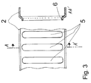
- Souls can have a ripple, and in particular a succession of punctures or openings in the longitudinal direction of the beam structure.
- At least one sole is made of a metallic material with a limit of high elasticity and the soul (s) is (are) made of a second metal with a limit lower elasticity than the first metal.
- At least one sole is made of steel with yield strength greater than 400 Mpa or aluminum with a limit elasticity greater than 200 Mpa.
- the two soles are made of the same metal, possibly with different thicknesses, or in different metals, a first sole being made of a metal having a yield strength / breaking load ratio which is lower or higher than that of the metal making the other sole.
- the beam structure comprises at least two essentially parallel soles connected between they by at least two souls also essentially parallels where the soles and the souls are made in metallic materials distinct by their nature, their mechanical properties or their thickness.
- the invention also relates to a method of assembling components of a beam structure, as described above, characterized in that the assembly is carried out of at least two components to form a section of joining by a fusion joining process such as spot welding.
- the assembly of at least minus two components to form a junction section is achieved by an assembly process by rivets, by simple crimping, by clinching.
- the assembly of at least two constituent elements in view to form a junction section is achieved by a assembly process by hem crimping.
- the ratio of the radius to the sum of the thicknesses of the various constituent elements along the joining section is included, from preferably between 2 and 10.
- the ratio of the difference between the radius and the thickness of the element the outermost with the thickness of the element the most interior is preferably greater than 2 and the ratio the thickness of the two elements is preferably less to 4.
- the assembly process presented by the invention provides a beam structure having a non-constant section and varying according to the height and / or width.
- the assembly operations mechanical are made using a press.
- the assembly by crimping per hem is produced in the same press cycle.
- Figure 1 shows a sectional view of a typical section of a beam structure according to this invention.
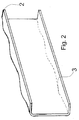
- Figure 2 shows an example of execution of a particular soul used for a structure of beam according to the present invention, and in particular such as shown in Figure 1.
- Figure 3 shows another example execution of a soul which can be used for a beam structure, and in particular such that shown in Figure 1.
- Figure 4 shows the assembly carried out by hem of different pieces in order to achieve a beam structure as shown in figure 1.
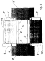
- Figure 5 shows all of the tools intended to carry out an assembly by hem to the press as shown in Figure 4.
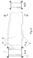
- Figure 6 shows a sectional view of a beam element with variable section along line A-A 'and along line B-B '.
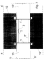
- Figure 7 shows a block diagram of a tool operating by press in order to allow the realization of a beam structure according to the present invention, and in particular as shown in the figure 1.
- the proposed solution is based on the use at least two metallic materials, in sheet or in sheet metal, distinct by their nature, their properties mechanical or their thickness in order to achieve a more elaborate structure. More specifically, this invention proposes to use steels with high mechanical properties in combination with steels more ductile to achieve a beam structure of optimized weight and possibly presenting a evolutionary section according to certain embodiments. he it is therefore a composite structure made from at least two distinct metallic materials by the nature, mechanical properties or by thickness.
- the stress level maximum is reached at the soles.
- the material chosen to make these soles must therefore have a yield point as high as possible. It is essentially the section of the sole that determines the moment of inertia: we must therefore be able to adjust width and thickness to optimize strength and size.
- the soles can optionally be made in two metallic materials distinct at least in nature, mechanical properties or thickness, for example for optimize the weight of the beam according to stresses or space constraints.
- the core that connects the soles is subjected to the bending but above all is the seat of constraints of shear and can be locally stressed in compression. To optimize the weight, you must be able to use a minimum metal thickness. This can be achieved by giving souls a geometry improving their buckling resistance. This implies that the metal used for souls must have ductility better than the metal used for the soles, i.e. a yield strength / breaking load ratio lower, and certainly less than 0.9.
- the soles 1 and 1 ' are produced in a sheet or sheet metal with a limit of very high elasticity, a steel weakly alloyed with carbon, for example.
- the elastic limit is chosen as high as possible.
- steel it will be located in a range of 400 to 1500 MPa, for aluminum between 200 and 800 MPa: the metal can then have a very limited formatting capacity.
- Cores 2 and 2 ' are made of metal in sheet or sheet with better ductility than the metal of the soles, so a level of relationship yield strength on substantially breaking load lower, and in any case less than 0.9.
- Souls 2 and 2 ' are not necessarily planar but present by example a ripple 3.
- a typical example of realization of souls is shown in Figure 2. The purpose of this ripple is to strengthen the buckling resistance of cores: one can thus significantly reduce their thickness.
- the soles and the souls are joined to the level of the junction zones 4 by a welding process or mechanical assembly.
- welding processes we may consider for example spot welding, the seam welding, laser welding, welding by diffusion, soldering.
- mechanical assembly processes like assembly by rivets, assembly without rivet by local deformation known as clinching, the crimping.
- a particularly interesting variant of assembly method is hem assembly.
- This guy assembly applied for example for boxes of canned can be made by press or by tools rotary type knobs.
- a typical example of this type assembly applied to the present invention is shown in Figure 4.
- a hem 7 is made at of each junction zone sole 1 / core 2.
- the advantage of this type of assembly is twofold: by its geometry, it helps strengthen the structure and it can be achieved using very productive processes like a press stamping or profiling machine.
- Figure 5 shows an example of tooling allowing to carry out this assembly by hem to the hurry.
- the soles 1 and the cores 2 are prepared for of the hem formation as indicated in 9: they receive a preform which initiates the hem.
- the pieces are then placed in the tool which is composed of the elements mobile 10, 10 'and 11, 11'. These elements are therefore first apart, horizontally for 11 and 11 ', vertically for 10 and 10 '. Parts 1 and 1 'are deposited on 11 and 11' respectively and maintained by means not shown, a magnetic system for example.
- the cores 2 and 2 ' are deposited on the mobile elements 10 and 10 'which match the shape of the ripple 3.
- Tools 8 are then moved simultaneously or successively to form the hem and be in the position indicated by 8 ', 8 "and 8".
- This type of tool can be mounted on a press, the elements 11 being moved by a cam system generating horizontal movement when closing of the press, elements 10, 8 and 8 'being put in action by the upper slide of the press: 10 is spring-mounted and its stroke is limited by a stop not shown, 8 and 8 'are directly attached to the press slide.
- Figure 6 shows a view of an element of beam with variable section: section A-A 'is more wide and taller than section B-B '.
- this type of hem assembly can also be performed using knurled tools according to methods known from elsewhere.
- the system can then be integrated into a line profiling.
- Figure 7 shows the block diagram of such assembly by rollers.
- Two rollers 13 and 13 ' b-b 'vertical axes hold the soles laterally, the hem being produced by two rollers 12, 12 'of horizontal a-a' axes.
- several rolls of pebbles like described in Figure 7 can be used to achieve hem gradually.
Landscapes
- Engineering & Computer Science (AREA)
- Architecture (AREA)
- Civil Engineering (AREA)
- Structural Engineering (AREA)
- Chemical & Material Sciences (AREA)
- Composite Materials (AREA)
- Rod-Shaped Construction Members (AREA)
- Bridges Or Land Bridges (AREA)
- Forging (AREA)
- Pressure Welding/Diffusion-Bonding (AREA)
- Joining Of Building Structures In Genera (AREA)
- Chemical Or Physical Treatment Of Fibers (AREA)
- Micromachines (AREA)
- Superconductors And Manufacturing Methods Therefor (AREA)
Priority Applications (8)
| Application Number | Priority Date | Filing Date | Title |
|---|---|---|---|
| EP99202192A EP1067250A1 (de) | 1999-07-05 | 1999-07-05 | Trägerstruktur und Verfahren zur Herstellung |
| CA002378637A CA2378637A1 (en) | 1999-07-05 | 2000-07-05 | Beam structure and method for producing such structures |
| AU57985/00A AU770680B2 (en) | 1999-07-05 | 2000-07-05 | Beam structure and method for producing such structures |
| DE60005668T DE60005668T2 (de) | 1999-07-05 | 2000-07-05 | Trägerstruktur und verfahren zur herstellung |
| AT00943492T ATE251262T1 (de) | 1999-07-05 | 2000-07-05 | Trägerstruktur und verfahren zur herstellung |
| PCT/BE2000/000079 WO2001002663A1 (fr) | 1999-07-05 | 2000-07-05 | Structure de poutre et procede de realisation de telles structures |
| EP00943492A EP1190148B1 (de) | 1999-07-05 | 2000-07-05 | Trägerstruktur und verfahren zur herstellung |
| US10/035,220 US6550211B2 (en) | 1999-07-05 | 2002-01-04 | Girder structure and method for producing such structures |
Applications Claiming Priority (1)
| Application Number | Priority Date | Filing Date | Title |
|---|---|---|---|
| EP99202192A EP1067250A1 (de) | 1999-07-05 | 1999-07-05 | Trägerstruktur und Verfahren zur Herstellung |
Publications (1)
| Publication Number | Publication Date |
|---|---|
| EP1067250A1 true EP1067250A1 (de) | 2001-01-10 |
Family
ID=8240415
Family Applications (2)
| Application Number | Title | Priority Date | Filing Date |
|---|---|---|---|
| EP99202192A Withdrawn EP1067250A1 (de) | 1999-07-05 | 1999-07-05 | Trägerstruktur und Verfahren zur Herstellung |
| EP00943492A Expired - Lifetime EP1190148B1 (de) | 1999-07-05 | 2000-07-05 | Trägerstruktur und verfahren zur herstellung |
Family Applications After (1)
| Application Number | Title | Priority Date | Filing Date |
|---|---|---|---|
| EP00943492A Expired - Lifetime EP1190148B1 (de) | 1999-07-05 | 2000-07-05 | Trägerstruktur und verfahren zur herstellung |
Country Status (7)
| Country | Link |
|---|---|
| US (1) | US6550211B2 (de) |
| EP (2) | EP1067250A1 (de) |
| AT (1) | ATE251262T1 (de) |
| AU (1) | AU770680B2 (de) |
| CA (1) | CA2378637A1 (de) |
| DE (1) | DE60005668T2 (de) |
| WO (1) | WO2001002663A1 (de) |
Cited By (1)
| Publication number | Priority date | Publication date | Assignee | Title |
|---|---|---|---|---|
| WO2015054417A1 (en) * | 2013-10-09 | 2015-04-16 | Brigham Young University | Structural members and related methods and systems |
Families Citing this family (9)
| Publication number | Priority date | Publication date | Assignee | Title |
|---|---|---|---|---|
| GB2368041B (en) * | 2000-10-17 | 2004-04-21 | Intelligent Engineering | Sandwich plate stepped risers |
| US6976343B2 (en) * | 2003-04-24 | 2005-12-20 | Mcgushion Kevin D | Compressive flange sinusoidal structural member |
| US7721496B2 (en) * | 2004-08-02 | 2010-05-25 | Tac Technologies, Llc | Composite decking material and methods associated with the same |
| US7930866B2 (en) * | 2004-08-02 | 2011-04-26 | Tac Technologies, Llc | Engineered structural members and methods for constructing same |
| US8266856B2 (en) | 2004-08-02 | 2012-09-18 | Tac Technologies, Llc | Reinforced structural member and frame structures |
| US8065848B2 (en) | 2007-09-18 | 2011-11-29 | Tac Technologies, Llc | Structural member |
| CA2575746C (en) * | 2004-08-02 | 2011-03-01 | Tac Technologies, Llc | Engineered structural members and methods for constructing same |
| CN100363575C (zh) * | 2005-05-27 | 2008-01-23 | 浙江大学 | 设置连杆的开口薄壁型钢 |
| CN108442510A (zh) * | 2018-03-13 | 2018-08-24 | 盐城工业职业技术学院 | 一种钢结构抗震框架结构和建筑 |
Citations (8)
| Publication number | Priority date | Publication date | Assignee | Title |
|---|---|---|---|---|
| FR1234371A (fr) * | 1959-05-13 | 1960-10-17 | Poutre alvéolaire ainsi que procédés et dispositifs pour l'exécution de poutres soudées, en particulier de poutres alvéolaires | |
| FR1312864A (fr) * | 1962-01-29 | 1962-12-21 | Cleveland Crane Eng | Poutre-rail pour système de manutention et procédé de fabrication de cette poutrerail |
| DE2221330A1 (de) * | 1972-04-29 | 1973-11-15 | Schultz Hans Georg Dr Ing | Gewichtsverminderung gebauter traeger durch unterdruecktes oder gerade erreichtes stegfliessen |
| US3960637A (en) * | 1973-07-23 | 1976-06-01 | Ostrow Paul F | Composite structural member |
| US3999354A (en) * | 1975-07-31 | 1976-12-28 | Alcan Aluminum Corporation | Structural member and box beam employing same |
| DE3425495A1 (de) * | 1984-07-11 | 1986-01-23 | Franzen & Spelten Consulting GmbH, 4054 Nettetal | Stahlprofiltraeger |
| GB2187409A (en) * | 1986-03-05 | 1987-09-09 | British Steel Corp | Channel section member |
| US5483782A (en) * | 1994-01-03 | 1996-01-16 | Hall; Donald M. | Load bearing beam having corrosion resistant cladding |
Family Cites Families (3)
| Publication number | Priority date | Publication date | Assignee | Title |
|---|---|---|---|---|
| US4734146A (en) * | 1986-03-31 | 1988-03-29 | Rockwell International Corporation | Method of producing a composite sine wave beam |
| US5600932A (en) * | 1996-01-05 | 1997-02-11 | Paik; Young J. | Beam with enhanced bearing load strength and method of manufacture |
| US6374570B1 (en) * | 2000-08-25 | 2002-04-23 | Lockheed Martin Corporation | Apparatus and method for joining dissimilar materials to form a structural support member |
-
1999
- 1999-07-05 EP EP99202192A patent/EP1067250A1/de not_active Withdrawn
-
2000
- 2000-07-05 DE DE60005668T patent/DE60005668T2/de not_active Expired - Fee Related
- 2000-07-05 AU AU57985/00A patent/AU770680B2/en not_active Ceased
- 2000-07-05 CA CA002378637A patent/CA2378637A1/en not_active Abandoned
- 2000-07-05 WO PCT/BE2000/000079 patent/WO2001002663A1/fr not_active Ceased
- 2000-07-05 EP EP00943492A patent/EP1190148B1/de not_active Expired - Lifetime
- 2000-07-05 AT AT00943492T patent/ATE251262T1/de not_active IP Right Cessation
-
2002
- 2002-01-04 US US10/035,220 patent/US6550211B2/en not_active Expired - Fee Related
Patent Citations (8)
| Publication number | Priority date | Publication date | Assignee | Title |
|---|---|---|---|---|
| FR1234371A (fr) * | 1959-05-13 | 1960-10-17 | Poutre alvéolaire ainsi que procédés et dispositifs pour l'exécution de poutres soudées, en particulier de poutres alvéolaires | |
| FR1312864A (fr) * | 1962-01-29 | 1962-12-21 | Cleveland Crane Eng | Poutre-rail pour système de manutention et procédé de fabrication de cette poutrerail |
| DE2221330A1 (de) * | 1972-04-29 | 1973-11-15 | Schultz Hans Georg Dr Ing | Gewichtsverminderung gebauter traeger durch unterdruecktes oder gerade erreichtes stegfliessen |
| US3960637A (en) * | 1973-07-23 | 1976-06-01 | Ostrow Paul F | Composite structural member |
| US3999354A (en) * | 1975-07-31 | 1976-12-28 | Alcan Aluminum Corporation | Structural member and box beam employing same |
| DE3425495A1 (de) * | 1984-07-11 | 1986-01-23 | Franzen & Spelten Consulting GmbH, 4054 Nettetal | Stahlprofiltraeger |
| GB2187409A (en) * | 1986-03-05 | 1987-09-09 | British Steel Corp | Channel section member |
| US5483782A (en) * | 1994-01-03 | 1996-01-16 | Hall; Donald M. | Load bearing beam having corrosion resistant cladding |
Cited By (2)
| Publication number | Priority date | Publication date | Assignee | Title |
|---|---|---|---|---|
| WO2015054417A1 (en) * | 2013-10-09 | 2015-04-16 | Brigham Young University | Structural members and related methods and systems |
| US9200442B2 (en) | 2013-10-09 | 2015-12-01 | Brigham Young University | Structural members and related methods and systems |
Also Published As
| Publication number | Publication date |
|---|---|
| CA2378637A1 (en) | 2001-01-11 |
| DE60005668D1 (de) | 2003-11-06 |
| EP1190148A1 (de) | 2002-03-27 |
| ATE251262T1 (de) | 2003-10-15 |
| AU5798500A (en) | 2001-01-22 |
| EP1190148B1 (de) | 2003-10-01 |
| US6550211B2 (en) | 2003-04-22 |
| US20020053178A1 (en) | 2002-05-09 |
| DE60005668T2 (de) | 2004-08-12 |
| WO2001002663A1 (fr) | 2001-01-11 |
| AU770680B2 (en) | 2004-02-26 |
Similar Documents
| Publication | Publication Date | Title |
|---|---|---|
| EP1109702B1 (de) | Kraftfahrzeugstossstangenträger | |
| EP1190148B1 (de) | Trägerstruktur und verfahren zur herstellung | |
| EP2147271A2 (de) | Massgeschneiderter geschweisster sitz und komponenten | |
| FR2690642A1 (fr) | Matrice à utiliser avec un poinçon pour assembler des feuilles et procédé d'assemblage de feuilles. | |
| EP0883452A1 (de) | Herstellungsverfahren eines kippkübelkörpers mit konkavem profil | |
| FR2802453A1 (fr) | Procede d'assemblage sans soudure de toles, de type boutonnage | |
| FR2809780A1 (fr) | Rivet de serrage en alluminium | |
| EP2310153B1 (de) | Verfahren zur formung mehrerer varianten eines metallblechteils sowie formungswerkzeug und -vorrichtung zur anwendung dieses verfahrens | |
| FR2850304A1 (fr) | Procede et dispositif pour la fabrication d'un flan variant en epaisseur au moins dans une zone | |
| FR2979608A1 (fr) | Dispositif de renfort lateral a couches de renfort pour un montant a mi longueur d'un cote de caisse de vehicule automobile | |
| EP3286028A1 (de) | Extrudierte verstärkungsträger mit programmierter verformung | |
| FR2907040A1 (fr) | Procede d'assemblage d'une structure comportant un exterieur et un interieur constituee d'une pluralite d'elements a double peau,telle qu'une caisse de vehicule ferroviaire,et structure obtenue. | |
| EP1192016B1 (de) | Verbindungsverfahren von minimal zwei metallischen bauteilen zur herstellung einer struktur | |
| EP0839593B1 (de) | Verfahren zum Herstellen eines Hohlrevolutionskörpers durch Fliessdrehen | |
| EP2032419A1 (de) | Mittels stumpfverbindung erzeugtes strukturelement für ein kraftfahrzeug | |
| FR2873608A1 (fr) | Procede pour renforcer localement une structure metallique mince | |
| EP0791415B1 (de) | Verfahren zur Herstellung eines Kraftfahrzeugdachs, Fahrzeugdach und Fahrzeug mit diesem Dach | |
| FR2748677A1 (fr) | Procede de forgeage a froid pour fabriquer des moyeux d'embrayages de vehicules automobiles | |
| EP2190685A2 (de) | Türband für automobil, tür für automobil und herstellungsverfahren dafür | |
| FR2865667A1 (fr) | Procede de fabrication d'un element metallique a profil constant. element issu du procede | |
| FR3033131A1 (fr) | Glissiere pour ses systemes de reglage coulissants et procede d'assemblage | |
| FR2699838A1 (fr) | Procédé de cintrage d'un assemblage de profilés métalliques et de tôles minces. | |
| FR2926054A1 (fr) | Piece de renfort a tres haute ou ultra haute limite elastique pour une structure de carrosserie de vehicule automobile. | |
| EP2593260A1 (de) | Montage einer dünnschicht und eines hohlprofilteils durch einseitiges induktionslöten und zugehöriges verfahrenr | |
| FR2785955A1 (fr) | Absorbeur de choc gigogne metallique et son procede de fabrication |
Legal Events
| Date | Code | Title | Description |
|---|---|---|---|
| PUAI | Public reference made under article 153(3) epc to a published international application that has entered the european phase |
Free format text: ORIGINAL CODE: 0009012 |
|
| AK | Designated contracting states |
Kind code of ref document: A1 Designated state(s): AT BE CH CY DE DK ES FI FR GB GR IE IT LI LU MC NL PT SE |
|
| AX | Request for extension of the european patent |
Free format text: AL;LT;LV;MK;RO;SI |
|
| AKX | Designation fees paid | ||
| REG | Reference to a national code |
Ref country code: DE Ref legal event code: 8566 |
|
| STAA | Information on the status of an ep patent application or granted ep patent |
Free format text: STATUS: THE APPLICATION IS DEEMED TO BE WITHDRAWN |
|
| 18D | Application deemed to be withdrawn |
Effective date: 20010711 |