EP1067332A2 - Lampe pour véhicule - Google Patents
Lampe pour véhicule Download PDFInfo
- Publication number
- EP1067332A2 EP1067332A2 EP00114364A EP00114364A EP1067332A2 EP 1067332 A2 EP1067332 A2 EP 1067332A2 EP 00114364 A EP00114364 A EP 00114364A EP 00114364 A EP00114364 A EP 00114364A EP 1067332 A2 EP1067332 A2 EP 1067332A2
- Authority
- EP
- European Patent Office
- Prior art keywords
- light
- peltier element
- temperature
- vehicle lamp
- cooling side
- Prior art date
- Legal status (The legal status is an assumption and is not a legal conclusion. Google has not performed a legal analysis and makes no representation as to the accuracy of the status listed.)
- Withdrawn
Links
Images

Classifications
-
- F—MECHANICAL ENGINEERING; LIGHTING; HEATING; WEAPONS; BLASTING
- F21—LIGHTING
- F21V—FUNCTIONAL FEATURES OR DETAILS OF LIGHTING DEVICES OR SYSTEMS THEREOF; STRUCTURAL COMBINATIONS OF LIGHTING DEVICES WITH OTHER ARTICLES, NOT OTHERWISE PROVIDED FOR
- F21V29/00—Protecting lighting devices from thermal damage; Cooling or heating arrangements specially adapted for lighting devices or systems
-
- F—MECHANICAL ENGINEERING; LIGHTING; HEATING; WEAPONS; BLASTING
- F21—LIGHTING
- F21S—NON-PORTABLE LIGHTING DEVICES; SYSTEMS THEREOF; VEHICLE LIGHTING DEVICES SPECIALLY ADAPTED FOR VEHICLE EXTERIORS
- F21S43/00—Signalling devices specially adapted for vehicle exteriors, e.g. brake lamps, direction indicator lights or reversing lights
- F21S43/10—Signalling devices specially adapted for vehicle exteriors, e.g. brake lamps, direction indicator lights or reversing lights characterised by the light source
- F21S43/13—Signalling devices specially adapted for vehicle exteriors, e.g. brake lamps, direction indicator lights or reversing lights characterised by the light source characterised by the type of light source
- F21S43/14—Light emitting diodes [LED]
-
- F—MECHANICAL ENGINEERING; LIGHTING; HEATING; WEAPONS; BLASTING
- F21—LIGHTING
- F21S—NON-PORTABLE LIGHTING DEVICES; SYSTEMS THEREOF; VEHICLE LIGHTING DEVICES SPECIALLY ADAPTED FOR VEHICLE EXTERIORS
- F21S45/00—Arrangements within vehicle lighting devices specially adapted for vehicle exteriors, for purposes other than emission or distribution of light
- F21S45/40—Cooling of lighting devices
- F21S45/42—Forced cooling
-
- F—MECHANICAL ENGINEERING; LIGHTING; HEATING; WEAPONS; BLASTING
- F21—LIGHTING
- F21Y—INDEXING SCHEME ASSOCIATED WITH SUBCLASSES F21K, F21L, F21S and F21V, RELATING TO THE FORM OR THE KIND OF THE LIGHT SOURCES OR OF THE COLOUR OF THE LIGHT EMITTED
- F21Y2115/00—Light-generating elements of semiconductor light sources
- F21Y2115/10—Light-emitting diodes [LED]
-
- H—ELECTRICITY
- H10—SEMICONDUCTOR DEVICES; ELECTRIC SOLID-STATE DEVICES NOT OTHERWISE PROVIDED FOR
- H10H—INORGANIC LIGHT-EMITTING SEMICONDUCTOR DEVICES HAVING POTENTIAL BARRIERS
- H10H20/00—Individual inorganic light-emitting semiconductor devices having potential barriers, e.g. light-emitting diodes [LED]
- H10H20/80—Constructional details
- H10H20/85—Packages
- H10H20/858—Means for heat extraction or cooling
- H10H20/8584—Means for heat extraction or cooling electrically controlled, e.g. Peltier elements
-
- H—ELECTRICITY
- H10—SEMICONDUCTOR DEVICES; ELECTRIC SOLID-STATE DEVICES NOT OTHERWISE PROVIDED FOR
- H10W—GENERIC PACKAGES, INTERCONNECTIONS, CONNECTORS OR OTHER CONSTRUCTIONAL DETAILS OF DEVICES COVERED BY CLASS H10
- H10W90/00—Package configurations
Definitions
- the invention relates to a vehicle lamp, in particular a Signal light, with at least one light-emitting diode as light source, which are thermally conductively connected to a heat dissipation device
- Such a vehicle lamp is known from EP 0 202 335 B1. It has a printed circuit board with a matrix on the front with a variety of grouped in multiple rows and columns LEDs is arranged. At the back of the circuit board is a finned heat sink arranged as heat dissipation device, the one with the back of the circuit board over a thermally conductive Absorber is connected.
- the finned heat sink allows one certain reduction in the operating temperature of the on the circuit board located LEDs, however, has the disadvantage that the over the heat dissipated heat output from the ambient temperature is dependent and with increasing ambient temperature decreases. Especially in those that occur in vehicle lights high operating temperatures of up to 90 ° Celsius is therefore one effective cooling of the LEDs is practically no longer possible.
- the LEDs In order to operate continuously even at these high temperatures, the LEDs must be used are supplied with a correspondingly low operating current, so that the power loss occurring at the light emitting diodes accordingly is low. Because the light intensity of the LEDs is roughly proportional to their operating current is obtained when the Operating current but also a correspondingly low light output. For example, at an operating temperature of 80 ° C Operating current of the LEDs compared to an operating temperature from about 25 ° C to about half, which means the luminous intensity emitted by the light-emitting diodes also increases approximately reduced by half. In addition, LEDs also have another negative temperature coefficient, i.e. their light intensity decreases with increasing operating or junction temperature. So that the vehicle light even at high ambient temperatures required luminous intensity, the number of LEDs are chosen to be large enough. The vehicle lamp is therefore still comparatively expensive.
- a vehicle lamp is also known from DE 197 28 763 A1, where the light-emitting diodes are preceded by a PTC resistor (PTC thermistor) is, by means of which the operating current of the LEDs high ambient temperatures. This may cause medium and low ambient temperatures a greater light intensity can be achieved, however, the light intensity decreases at higher ones Ambient temperatures roughly proportional to the lowering of the Operating current of the LEDs.
- PTC thermistor PTC thermistor
- Another disadvantage is that change when changing the operating current of the LED Luminous color changes, which is particularly problematic with signal lights at which the wavelength of the emitted light is due statutory provisions in a fixed spectral range must lie. It is also disadvantageous that those in the PTC resistor implemented power loss also for heating the vehicle lamp contributes.
- the solution to this problem is that the heat dissipation device for cooling the light-emitting diode (s) as an active temperature control device is trained.
- the LEDs can then operate even at high ambient temperatures be cooled effectively, even cooling the LEDs are possible up to an operating temperature that is lower is than the ambient temperature.
- the number of LEDs can thus with the same light intensity compared to a conventional Vehicle light with passive heat sink significantly reduced be, i.e. LEDs can be saved.
- the invention Vehicle lights are therefore inexpensive to manufacture. Compared to a conventional vehicle lamp with passive Heatsink can also lower the operating current LEDs reduced and / or at high ambient temperatures be shifted to higher temperatures or even be dropped entirely.
- the vehicle lamp therefore has a largely from the Ambient temperature independent, constant light color. In advantageously results from the active Temperature control device reduced operating temperature of the LEDs but also a longer life of the LEDs and thus the entire vehicle light.
- the temperature control device at least one Peltier element with a cooling side and a heating side and if the LED (s) with the cooling side of the Peltier element is (are) thermally conductively connected.
- the result is a simple, compact temperature control device, which is also inexpensive to manufacture. If necessary, you can even several Peltier elements connected together in a stack be, whereby an even more effective cooling of the LED (s) can be achieved. Two are adjacent stacked Peltier elements the cooling side of one Peltier element with the heat side of the other, adjacent to it Peltier element connected.
- the temperature control device for regulating the Temperature of the LED (s) with a temperature control device has a temperature sensor.
- the operating temperature of the LEDs can then largely independent of the ambient temperature kept constant or at a predetermined temperature be limited.
- the Temperature control device may be completely switched off, whereby in a tempering device having a Peltier element the electrical energy for operating the Peltier element is saved can be.
- the light-emitting diode (s) connected to a power supply device that one a current control input connected to a temperature sensor temperature-dependent setting of the LED operating current having.
- the operating current can then be above a critical Temperature can be lowered.
- the vehicle lamp can thereby operated even higher ambient temperatures in continuous operation be without the LED (s) being thermally damaged (become).
- the LEDs are immediately after the Switching on the Peltier element before thermal overload protected when the cooling side of the Peltier element reaches its operating temperature has not yet reached.
- the current control input of the power supply device indirectly via a microprocessor with the temperature sensor is connected and if the microprocessor has a data memory is assigned in which for different temperature measurements of the temperature sensor a setpoint for the LED current is saved.
- the temperature readings can and the light-emitting diode currents associated with this, for example in the form of value combinations or in the form of characteristic curves in the Data storage must be stored. If necessary, for the individual LED current setpoints even several temperature values defining the temporal temperature profile are stored be so that when setting the LED current a temporal change in the temperature of the LEDs and / or Environment can be taken into account.
- the temperature dependent Adjustment of the light emitting diode current can be done, for example a transistor connected to an output of the microprocessor respectively.
- the vehicle lamp is then particularly inexpensive to manufacture.
- circuit parts such as the microprocessor, the data memory, at least one power transistor for adjustment of the LED current and / or at least one temperature sensor in hybrid technology with the circuit board or the cooling side of the Peltier element can be integrated.
- the semiconductor chips are expediently located LEDs each with their facing away from the emission sides Back preferably flat on the cooling side of the Peltier element or on the front of a Peltier element facing away from one connected on the back to the Peltier element in a heat-conducting manner Circuit board.
- the light emitting diodes can then cover a large area and thus be cooled particularly effectively.
- the cooling side and the Thermal side of the Pelt quarter element delimiting each other Isolation is provided and if this is preferably by a Cooling side with luminaire housing bordering the light-emitting diodes is.
- the LEDs are then inside the luminaire housing thermally connected to the cooling side of the Peltier element and through the wall of the lamp housing against the heat side of the Peltier element thermally insulated.
- the on the LEDs Loss of heat that occurs can then be better from the LEDs be dissipated.
- the wall of the Luminaire housing can be a lens and / or optical Have elements such as diffusing lenses.
- the vehicle light connection points to thermally conductive connection of the heating side of the Peltier element having a vehicle body.
- the on the heating side of the Peltier element emitted heat can then be thermally good conductive part of the vehicle body, for example a sheet metal part be derived.
- the outer contour of the vehicle lamp can on the Connection point to the vehicle body to be adapted to extensive heat transfer into the vehicle body enable.
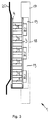
- a vehicle lamp designated as a whole has 1 as Light sources several light emitting diodes 2, each with the Cooling side 3 of a cooling side 3 and a heating side 4 having Peltier element are thermally conductively connected.
- Fig. 1 can be seen that the LEDs 2 in a matrix in several Rows and columns arranged on the cooling side 3 of the Peltier element are.
- the cooling side 3 and the heating side 4 of the Peltier element are each plate-shaped and consist of a thermally good conductive and electrically insulating material, for example Ceramics.
- a thermally good conductive and electrically insulating material for example Ceramics.
- Peltier cell 5 There are a large number between the cooling side 3 and the heating side 4 of semiconductor elements in several rows and columns side by side arranged, each forming a Peltier cell 5.
- the single ones Peltier cells 5 are each with their cold end with the LEDs 2 facing away from the cooling side 3 and with their warm end with the back of the cooling side 3 facing Heating side 4 thermally connected.
- the cooling side 3 and the heating side 4 each have their mutually facing flat sides conductor tracks, which as Power supply for the Peltier cells 5 serve.
- the Peltier element enables effective cooling of the LEDs 2, so that even at high ambient temperatures with a comparatively large continuous operating current can be supplied without to take thermal damage.
- the LEDs 2 light up even at high ambient temperatures, for example at ambient temperatures of over 80 ° Celcius with great light intensity, so that to achieve a predetermined total light intensity of the vehicle lamp only a correspondingly small number of LEDs 2 is required.
- a temperature control device is used to regulate the temperature of the light-emitting diodes 2 6 with one with the cooling side 3 of the Peltier element thermally conductively connected temperature sensor 7 is provided.
- the temperature control device 6 has a power transistor, the Peltier cells 5 with the connection 8 for the positive pole connects a DC power supply.
- the on the cooling side 3 of the Peltier element arranged temperature control device is for this via a first conductor 9 with the connection 8 for the positive pole and via a second conductor 10 and a cooling side 3 the heating side 4 connecting bridge 11 at a first power supply connection of the Peltier element connected.
- the other Power supply connection of the Peltier element is with a Terminal 12 for the negative pole of the DC power supply connected.
- the operating current is above a predetermined temperature of the Peltier element for regulating the temperature of the light-emitting diodes 2 set by means of the temperature control device 6. Below this predetermined temperature is a cooling of the LEDs 2 not required by means of the Peltier element and the Peltier element is then switched off.
- the port 8 is on the Ignition switch of the vehicle in which the vehicle lamp 1 installed, connected to the vehicle's DC power supply, such that the temperature control device 6 and the Peltier element are only activated when the vehicle ignition is switched on. At the vehicle ignition is off the circuit from the DC power supply to the Peltier element interrupted.
- LEDs 2 are not called too large Operating current is energized and thus thermally overloaded, the operating current of the LEDs 2 by means of a microprocessor 13 depending on the temperature of the cooling side 3 of the Peltier element is limited to a predetermined value.
- the Microprocessor 13 is on the one hand with a temperature sensor 14 and on the other hand with adjusting elements 15 for adjusting the LED current connected.
- a temperature sensor 14 is on the one hand with a temperature sensor 14 and on the other hand with adjusting elements 15 for adjusting the LED current connected.
- adjusting elements 15 for adjusting the LED current connected.
- everyone is LED 2 each assigned its own control element 15, the for example one connected in series with the LED 2 May have transistor.
- the microprocessor 13 is connected to a data memory 16, in which for different temperature measurements of the temperature sensor 14 each store a setpoint for the LED current is. Temperature values 14 are used to determine actual values for the temperature of the cooling side 3 of the Peltier element is detected and in read the microprocessor 13. Based on that in the data store 16 stored parameters are the actual temperature values a target value for the LED current assigned by appropriate control of the control elements 15 is set.
- the electrical circuit of the Peltier element closed, provided that the temperature at the Cooling side 3 a predetermined temperature limit, for example Can be 60 ° Celcius and due to the temperature resistance of the LEDs 2 is specified.
- the Temperature on the cooling side 3 then increases based on the Turn on the ignition switch existing starting temperature continuously until the specified temperature limit is reached becomes. Should the cooling performance of the Peltier element at high Ambient temperatures are not sufficient to open the cooling side 3 to cool down the specified temperature limit, that will Peltier element energized with the maximum operating current. At the Cooling side 3 will then face one after a while Ambient temperature lower temperature.
- the LEDs 2 become dependent energized by the respective temperature on the cooling side 3. there the LED current increases until the temperature on the cooling side 3 has reached the specified temperature limit. Below of the temperature limit, the LEDs 2 with a constant, independent of the temperature LED current operated.
- the lamp housing 17 On the cooling side 3 is a lamp housing 17 with a transparent Lens 18 arranged which the light emitting diodes 2nd covered.
- the lamp housing 17 has an inner cavity 19, in which the LEDs 2 between the cooling side 3 and the Lens 18 are arranged.
- the inner cavity 19 laterally boundary edge of the lamp housing 17 is with the cooling side 3 of the Peltier element tightly connected.
- the LEDs 2 are in the inner cavity 19 at a distance from the Housing walls of the lamp housing 17 arranged.
- the inner cavity 19 can, for example, be evacuated or, for example, with air or another thermally insulating gas.
- Fig. 3 it can be seen that the vehicle lamp 1 on the heating side 4 of the Peltier element with the sheet metal of the vehicle body Has 20 connected connection point. It can be clearly seen that the heating side 4 flat on the sheet metal of the vehicle body 20 is present. Thus, the heat given off on the heating side 3 can be Vehicle body 20 and are derived from there to the environment.
Landscapes
- Engineering & Computer Science (AREA)
- General Engineering & Computer Science (AREA)
- Physics & Mathematics (AREA)
- Microelectronics & Electronic Packaging (AREA)
- Optics & Photonics (AREA)
- Arrangement Of Elements, Cooling, Sealing, Or The Like Of Lighting Devices (AREA)
- Led Device Packages (AREA)
- Non-Portable Lighting Devices Or Systems Thereof (AREA)
Applications Claiming Priority (2)
| Application Number | Priority Date | Filing Date | Title |
|---|---|---|---|
| DE19932051A DE19932051A1 (de) | 1999-07-09 | 1999-07-09 | Fahrzeugleuchte |
| DE19932051 | 1999-07-09 |
Publications (2)
| Publication Number | Publication Date |
|---|---|
| EP1067332A2 true EP1067332A2 (fr) | 2001-01-10 |
| EP1067332A3 EP1067332A3 (fr) | 2001-10-10 |
Family
ID=7914218
Family Applications (1)
| Application Number | Title | Priority Date | Filing Date |
|---|---|---|---|
| EP00114364A Withdrawn EP1067332A3 (fr) | 1999-07-09 | 2000-07-05 | Lampe pour véhicule |
Country Status (2)
| Country | Link |
|---|---|
| EP (1) | EP1067332A3 (fr) |
| DE (1) | DE19932051A1 (fr) |
Cited By (16)
| Publication number | Priority date | Publication date | Assignee | Title |
|---|---|---|---|---|
| EP1408476A1 (fr) * | 2002-10-10 | 2004-04-14 | Barco N.V. | Arrangements d'écran d'affichage luminescent |
| EP1408475A1 (fr) * | 2002-10-11 | 2004-04-14 | Barco N.V. | Arrangements d'écran d'affichage luminescent |
| WO2004038290A1 (fr) * | 2002-10-28 | 2004-05-06 | Dialight Corporation | Lampe a eclairage de diode electroluminescente a controle de chaleur thermoelectrique |
| WO2005062089A1 (fr) * | 2003-12-02 | 2005-07-07 | 3M Innovative Properties Company | Dispositif lumineux a semi-conducteur |
| WO2006033998A1 (fr) * | 2004-09-16 | 2006-03-30 | Magna International Inc. | Systeme de gestion thermique destine a des eclairages a semi-conducteurs pour automobiles |
| WO2006066532A1 (fr) * | 2004-12-22 | 2006-06-29 | Patent-Treuhand- Gesellschaft Für Elektrische Glühlampen Mbh | Dispositif d'eclairage ayant au moins une diode electroluminescente et phare |
| US7157838B2 (en) | 2002-10-10 | 2007-01-02 | Barco N.V. | Light emission display arrangements |
| US7163327B2 (en) | 2002-12-02 | 2007-01-16 | 3M Innovative Properties Company | Illumination system using a plurality of light sources |
| US7189983B2 (en) | 2003-12-02 | 2007-03-13 | 3M Innovative Properties Company | LED modifying apparatus and method |
| US7403680B2 (en) | 2003-12-02 | 2008-07-22 | 3M Innovative Properties Company | Reflective light coupler |
| US7456805B2 (en) | 2003-12-18 | 2008-11-25 | 3M Innovative Properties Company | Display including a solid state light device and method using same |
| WO2009024134A1 (fr) * | 2007-08-20 | 2009-02-26 | Schmidt & Haensch Gmbh & Co. | Procédé et dispositif pour ajuster, de manière exacte et régulée, la longueur d'onde centroïde du rayonnement émis par une diode électroluminescente |
| US8240885B2 (en) | 2008-11-18 | 2012-08-14 | Abl Ip Holding Llc | Thermal management of LED lighting systems |
| EP2483920A4 (fr) * | 2009-09-28 | 2014-01-22 | Dialight Corp | Appareil d'utilisation de caloducs dans la régulation de la température d'une unité lumineuse del |
| DE102004047685B4 (de) * | 2004-09-30 | 2015-09-24 | Volkswagen Ag | Verfahren zum Steuern einer Fahrzeuglichtquelle und Steuergerät für eine Fahrzeuglichtquelle |
| CN115551741A (zh) * | 2020-05-06 | 2022-12-30 | 奥迪股份公司 | 用于机动车的前照灯 |
Families Citing this family (10)
| Publication number | Priority date | Publication date | Assignee | Title |
|---|---|---|---|---|
| DE10130809A1 (de) * | 2001-06-26 | 2003-01-02 | Hella Kg Hueck & Co | Scheinwerfer für Fahrzeuge |
| EP1512180A2 (fr) * | 2002-03-26 | 2005-03-09 | Enfis Limited | Appareil emetteur de lumiere refroidie |
| DE10313246A1 (de) * | 2003-03-25 | 2004-10-21 | Sitronic Gesellschaft für elektrotechnische Ausrüstung mbH. & Co. KG | Kraftfahrzeugleuchtenmodul |
| DE10319363A1 (de) * | 2003-04-29 | 2004-11-18 | Volkswagen Ag | Leuchtvorrichtung für Fahrzeuge und Verfahren zum Steuern und/oder Regeln einer Betauungsschutzvorrichtung einer Leuchtvorrichtung für Fahrzeuge |
| DE102004013680A1 (de) | 2004-03-18 | 2005-10-20 | Siemens Ag | Lichtquelle für Bilderzeugungseinheit |
| DE102004025624A1 (de) * | 2004-05-25 | 2005-12-15 | Hella Kgaa Hueck & Co. | Scheinwerfer mit Wärmetauscher zur Kühlung von Leuchtmitteln |
| DE102004025623A1 (de) * | 2004-05-25 | 2005-12-15 | Hella Kgaa Hueck & Co. | Scheinwerfer für ein Kraftfahrzeug |
| DE102004028987A1 (de) * | 2004-06-16 | 2006-01-05 | Volkswagen Ag | Verfahren zum Steuern einer Beleuchtungseinheit für ein Fahrzeug und Beleuchtungseinheit für ein Fahrzeug |
| DE102009019272B4 (de) * | 2009-04-28 | 2012-02-16 | Imm Photonics Gmbh | Temperaturstabilisierte Kollimator-Lichtquelle |
| DE102017124455A1 (de) | 2017-10-19 | 2019-04-25 | Osram Opto Semiconductors Gmbh | Optoelektronisches Bauteil mit einem Wirkungselement |
Citations (2)
| Publication number | Priority date | Publication date | Assignee | Title |
|---|---|---|---|---|
| EP0202335B1 (fr) | 1984-11-15 | 1989-10-25 | Japan Traffic Management Technology Association | Unite de signalisation possedant une fonction de dissipation de chaleur |
| DE19728763A1 (de) | 1997-07-07 | 1999-01-14 | Reitter & Schefenacker Gmbh | Schaltungseinrichtung zum Schutz von strombetriebenen Leuchtmitteln, insbesondere von LEDs, zu Signal- oder Beleuchtungszwecken |
Family Cites Families (9)
| Publication number | Priority date | Publication date | Assignee | Title |
|---|---|---|---|---|
| US3309565A (en) * | 1959-12-14 | 1967-03-14 | Mc Graw Edison Co | Light output of fluorescent lamps automatically held constant by means of peltier type coolers |
| US5156999A (en) * | 1990-06-08 | 1992-10-20 | Wai-Hon Lee | Packaging method for semiconductor laser/detector devices |
| US5528474A (en) * | 1994-07-18 | 1996-06-18 | Grote Industries, Inc. | Led array vehicle lamp |
| DE19528459C2 (de) * | 1995-08-03 | 2001-08-23 | Garufo Gmbh | Kühlung für ein mit LED's bestücktes Leuchtaggregat |
| US5612593A (en) * | 1995-08-30 | 1997-03-18 | Rockwell International | Fluorescent tube thermal management system utilizing thermal electric cooler units |
| US5936353A (en) * | 1996-04-03 | 1999-08-10 | Pressco Technology Inc. | High-density solid-state lighting array for machine vision applications |
| US5890794A (en) * | 1996-04-03 | 1999-04-06 | Abtahi; Homayoon | Lighting units |
| JP3180701B2 (ja) * | 1997-02-07 | 2001-06-25 | 日本電気株式会社 | 半導体レーザ装置 |
| DE69905760T2 (de) * | 1998-12-21 | 2004-03-18 | Alliedsignal Inc. | Hochleistungslampe mit infrarot-diode |
-
1999
- 1999-07-09 DE DE19932051A patent/DE19932051A1/de not_active Withdrawn
-
2000
- 2000-07-05 EP EP00114364A patent/EP1067332A3/fr not_active Withdrawn
Patent Citations (2)
| Publication number | Priority date | Publication date | Assignee | Title |
|---|---|---|---|---|
| EP0202335B1 (fr) | 1984-11-15 | 1989-10-25 | Japan Traffic Management Technology Association | Unite de signalisation possedant une fonction de dissipation de chaleur |
| DE19728763A1 (de) | 1997-07-07 | 1999-01-14 | Reitter & Schefenacker Gmbh | Schaltungseinrichtung zum Schutz von strombetriebenen Leuchtmitteln, insbesondere von LEDs, zu Signal- oder Beleuchtungszwecken |
Cited By (25)
| Publication number | Priority date | Publication date | Assignee | Title |
|---|---|---|---|---|
| US7157838B2 (en) | 2002-10-10 | 2007-01-02 | Barco N.V. | Light emission display arrangements |
| EP1408476A1 (fr) * | 2002-10-10 | 2004-04-14 | Barco N.V. | Arrangements d'écran d'affichage luminescent |
| EP1408475A1 (fr) * | 2002-10-11 | 2004-04-14 | Barco N.V. | Arrangements d'écran d'affichage luminescent |
| WO2004038290A1 (fr) * | 2002-10-28 | 2004-05-06 | Dialight Corporation | Lampe a eclairage de diode electroluminescente a controle de chaleur thermoelectrique |
| US7510303B2 (en) | 2002-10-28 | 2009-03-31 | Dialight Corporation | LED illuminated lamp with thermoelectric heat management |
| US7163327B2 (en) | 2002-12-02 | 2007-01-16 | 3M Innovative Properties Company | Illumination system using a plurality of light sources |
| US7329887B2 (en) | 2003-12-02 | 2008-02-12 | 3M Innovative Properties Company | Solid state light device |
| US7189983B2 (en) | 2003-12-02 | 2007-03-13 | 3M Innovative Properties Company | LED modifying apparatus and method |
| US7202489B2 (en) | 2003-12-02 | 2007-04-10 | 3M Innovative Properties Company | LED modifying apparatus and method |
| US7202490B2 (en) | 2003-12-02 | 2007-04-10 | 3M Innovative Properties Company | LED modifying apparatus and method |
| US7250611B2 (en) | 2003-12-02 | 2007-07-31 | 3M Innovative Properties Company | LED curing apparatus and method |
| US7403680B2 (en) | 2003-12-02 | 2008-07-22 | 3M Innovative Properties Company | Reflective light coupler |
| WO2005062089A1 (fr) * | 2003-12-02 | 2005-07-07 | 3M Innovative Properties Company | Dispositif lumineux a semi-conducteur |
| US7456805B2 (en) | 2003-12-18 | 2008-11-25 | 3M Innovative Properties Company | Display including a solid state light device and method using same |
| WO2006033998A1 (fr) * | 2004-09-16 | 2006-03-30 | Magna International Inc. | Systeme de gestion thermique destine a des eclairages a semi-conducteurs pour automobiles |
| US7575354B2 (en) | 2004-09-16 | 2009-08-18 | Magna International Inc. | Thermal management system for solid state automotive lighting |
| DE102004047685B4 (de) * | 2004-09-30 | 2015-09-24 | Volkswagen Ag | Verfahren zum Steuern einer Fahrzeuglichtquelle und Steuergerät für eine Fahrzeuglichtquelle |
| WO2006066532A1 (fr) * | 2004-12-22 | 2006-06-29 | Patent-Treuhand- Gesellschaft Für Elektrische Glühlampen Mbh | Dispositif d'eclairage ayant au moins une diode electroluminescente et phare |
| US9578716B2 (en) | 2006-06-30 | 2017-02-21 | Dialight Corporation | Apparatus for using heat pipes in controlling temperature of an LED light unit |
| WO2009024134A1 (fr) * | 2007-08-20 | 2009-02-26 | Schmidt & Haensch Gmbh & Co. | Procédé et dispositif pour ajuster, de manière exacte et régulée, la longueur d'onde centroïde du rayonnement émis par une diode électroluminescente |
| US8240885B2 (en) | 2008-11-18 | 2012-08-14 | Abl Ip Holding Llc | Thermal management of LED lighting systems |
| AU2010298662B2 (en) * | 2009-09-28 | 2015-07-09 | Dialight Corporation | Apparatus for using heat pipes in controlling temperature of an LED light unit |
| EP2483920A4 (fr) * | 2009-09-28 | 2014-01-22 | Dialight Corp | Appareil d'utilisation de caloducs dans la régulation de la température d'une unité lumineuse del |
| CN115551741A (zh) * | 2020-05-06 | 2022-12-30 | 奥迪股份公司 | 用于机动车的前照灯 |
| US12409774B2 (en) | 2020-05-06 | 2025-09-09 | Audi Ag | Headlight for a motor vehicle |
Also Published As
| Publication number | Publication date |
|---|---|
| DE19932051A1 (de) | 2001-01-11 |
| EP1067332A3 (fr) | 2001-10-10 |
Similar Documents
| Publication | Publication Date | Title |
|---|---|---|
| EP1067332A2 (fr) | Lampe pour véhicule | |
| EP0662209B1 (fr) | Dispositif thermoelectrique de chauffage ou de refrigeration | |
| DE102010030639B4 (de) | Leuchtvorrichtung mit beweglichem Konverterelement | |
| DE2737345C2 (de) | Halbleiterlaser-Vorrichtung mit einem Peltier-Element | |
| EP1771891B1 (fr) | Element électroluminescent et module lumineux | |
| DE60305060T2 (de) | Led-lampe mit thermoelektrischer wärmeregelung | |
| DE10110835B4 (de) | Beleuchtungsanordnung mit einer Mehrzahl von LED-Modulen auf einer Kühlkörperoberfläche | |
| EP3167224B1 (fr) | Lampe à semi-conducteur | |
| EP2198196B1 (fr) | Lampe | |
| DE102004060890A1 (de) | Kfz-Scheinwerferelement | |
| DE112011103148T5 (de) | Multichip-LED-Vorrichtungen mit hoher Dichte | |
| EP1995514A2 (fr) | Unité d'éclairage | |
| DE102005018175A1 (de) | LED-Modul und LED-Beleuchtungseinrichtung mit mehreren LED-Modulen | |
| DE102014222701A1 (de) | Ultraviolettbestrahlungskopf und Ultraviolettbestrahlungseinrichtung | |
| EP1777755A1 (fr) | Elément luminescent comprenant au moins un cristal luminescent | |
| DE8908049U1 (de) | Kühleinrichtung für Halbleiterpumplichtquellen | |
| DE19957452A1 (de) | Elektrische Heizeinrichtung, insbesondere für ein Kraftfahrzeug | |
| WO2009121330A2 (fr) | Dispositif d'éclairage | |
| DE102015118984B4 (de) | Lichtquelle | |
| WO2006034755A1 (fr) | Projecteurs de vehicules | |
| DE102008022834A1 (de) | Beleuchtungseinrichtung | |
| DE102004053680B4 (de) | Beleuchtungskörper | |
| DE102009022071A1 (de) | Kühlkörper für eine Leuchtvorrichtung | |
| DE102008010784B3 (de) | Wärmeabfuhrtechnisch polyvalente Wärmeübertragungsvorrichtung für wenigstens ein Halbleiterbauelement sowie zugehöriges Test- und Betriebsverfahren | |
| EP3740042B1 (fr) | Agencement et procédé de fonctionnement d'un composant semi-conducteur ainsi que luminaire |
Legal Events
| Date | Code | Title | Description |
|---|---|---|---|
| PUAI | Public reference made under article 153(3) epc to a published international application that has entered the european phase |
Free format text: ORIGINAL CODE: 0009012 |
|
| AK | Designated contracting states |
Kind code of ref document: A2 Designated state(s): AT BE CH CY DE DK ES FI FR GB GR IE IT LI LU MC NL PT SE |
|
| AX | Request for extension of the european patent |
Free format text: AL;LT;LV;MK;RO;SI |
|
| PUAL | Search report despatched |
Free format text: ORIGINAL CODE: 0009013 |
|
| AK | Designated contracting states |
Kind code of ref document: A3 Designated state(s): AT BE CH CY DE DK ES FI FR GB GR IE IT LI LU MC NL PT SE |
|
| AX | Request for extension of the european patent |
Free format text: AL;LT;LV;MK;RO;SI |
|
| RIC1 | Information provided on ipc code assigned before grant |
Free format text: 7F 21V 29/00 A, 7H 01L 33/00 B, 7F 21Y 101:02 Z, 7F 21W 101:14 Z |
|
| AKX | Designation fees paid | ||
| REG | Reference to a national code |
Ref country code: DE Ref legal event code: 8566 |
|
| STAA | Information on the status of an ep patent application or granted ep patent |
Free format text: STATUS: THE APPLICATION IS DEEMED TO BE WITHDRAWN |
|
| 18D | Application deemed to be withdrawn |
Effective date: 20020411 |