EP1067533A2 - Optisches Aufzeichnungsmedium und optisches Aufzeichnungs- und Wiedergabegerät - Google Patents
Optisches Aufzeichnungsmedium und optisches Aufzeichnungs- und Wiedergabegerät Download PDFInfo
- Publication number
- EP1067533A2 EP1067533A2 EP00113807A EP00113807A EP1067533A2 EP 1067533 A2 EP1067533 A2 EP 1067533A2 EP 00113807 A EP00113807 A EP 00113807A EP 00113807 A EP00113807 A EP 00113807A EP 1067533 A2 EP1067533 A2 EP 1067533A2
- Authority
- EP
- European Patent Office
- Prior art keywords
- layer
- optical recording
- set forth
- heat radiating
- optical
- Prior art date
- Legal status (The legal status is an assumption and is not a legal conclusion. Google has not performed a legal analysis and makes no representation as to the accuracy of the status listed.)
- Granted
Links
Images



Classifications
-
- G—PHYSICS
- G11—INFORMATION STORAGE
- G11B—INFORMATION STORAGE BASED ON RELATIVE MOVEMENT BETWEEN RECORD CARRIER AND TRANSDUCER
- G11B7/00—Recording or reproducing by optical means, e.g. recording using a thermal beam of optical radiation by modifying optical properties or the physical structure, reproducing using an optical beam at lower power by sensing optical properties; Record carriers therefor
- G11B7/24—Record carriers characterised by shape, structure or physical properties, or by the selection of the material
- G11B7/241—Record carriers characterised by shape, structure or physical properties, or by the selection of the material characterised by the selection of the material
- G11B7/252—Record carriers characterised by shape, structure or physical properties, or by the selection of the material characterised by the selection of the material of layers other than recording layers
-
- B—PERFORMING OPERATIONS; TRANSPORTING
- B82—NANOTECHNOLOGY
- B82Y—SPECIFIC USES OR APPLICATIONS OF NANOSTRUCTURES; MEASUREMENT OR ANALYSIS OF NANOSTRUCTURES; MANUFACTURE OR TREATMENT OF NANOSTRUCTURES
- B82Y10/00—Nanotechnology for information processing, storage or transmission, e.g. quantum computing or single electron logic
-
- G—PHYSICS
- G11—INFORMATION STORAGE
- G11B—INFORMATION STORAGE BASED ON RELATIVE MOVEMENT BETWEEN RECORD CARRIER AND TRANSDUCER
- G11B11/00—Recording on or reproducing from the same record carrier wherein for these two operations the methods are covered by different main groups of groups G11B3/00 - G11B7/00 or by different subgroups of group G11B9/00; Record carriers therefor
- G11B11/10—Recording on or reproducing from the same record carrier wherein for these two operations the methods are covered by different main groups of groups G11B3/00 - G11B7/00 or by different subgroups of group G11B9/00; Record carriers therefor using recording by magnetic means or other means for magnetisation or demagnetisation of a record carrier, e.g. light induced spin magnetisation; Demagnetisation by thermal or stress means in the presence or not of an orienting magnetic field
- G11B11/105—Recording on or reproducing from the same record carrier wherein for these two operations the methods are covered by different main groups of groups G11B3/00 - G11B7/00 or by different subgroups of group G11B9/00; Record carriers therefor using recording by magnetic means or other means for magnetisation or demagnetisation of a record carrier, e.g. light induced spin magnetisation; Demagnetisation by thermal or stress means in the presence or not of an orienting magnetic field using a beam of light or a magnetic field for recording by change of magnetisation and a beam of light for reproducing, i.e. magneto-optical, e.g. light-induced thermomagnetic recording, spin magnetisation recording, Kerr or Faraday effect reproducing
- G11B11/10582—Record carriers characterised by the selection of the material or by the structure or form
- G11B11/10584—Record carriers characterised by the selection of the material or by the structure or form characterised by the form, e.g. comprising mechanical protection elements
-
- G—PHYSICS
- G11—INFORMATION STORAGE
- G11B—INFORMATION STORAGE BASED ON RELATIVE MOVEMENT BETWEEN RECORD CARRIER AND TRANSDUCER
- G11B11/00—Recording on or reproducing from the same record carrier wherein for these two operations the methods are covered by different main groups of groups G11B3/00 - G11B7/00 or by different subgroups of group G11B9/00; Record carriers therefor
- G11B11/10—Recording on or reproducing from the same record carrier wherein for these two operations the methods are covered by different main groups of groups G11B3/00 - G11B7/00 or by different subgroups of group G11B9/00; Record carriers therefor using recording by magnetic means or other means for magnetisation or demagnetisation of a record carrier, e.g. light induced spin magnetisation; Demagnetisation by thermal or stress means in the presence or not of an orienting magnetic field
- G11B11/105—Recording on or reproducing from the same record carrier wherein for these two operations the methods are covered by different main groups of groups G11B3/00 - G11B7/00 or by different subgroups of group G11B9/00; Record carriers therefor using recording by magnetic means or other means for magnetisation or demagnetisation of a record carrier, e.g. light induced spin magnetisation; Demagnetisation by thermal or stress means in the presence or not of an orienting magnetic field using a beam of light or a magnetic field for recording by change of magnetisation and a beam of light for reproducing, i.e. magneto-optical, e.g. light-induced thermomagnetic recording, spin magnetisation recording, Kerr or Faraday effect reproducing
- G11B11/10582—Record carriers characterised by the selection of the material or by the structure or form
- G11B11/10586—Record carriers characterised by the selection of the material or by the structure or form characterised by the selection of the material
-
- G—PHYSICS
- G11—INFORMATION STORAGE
- G11B—INFORMATION STORAGE BASED ON RELATIVE MOVEMENT BETWEEN RECORD CARRIER AND TRANSDUCER
- G11B7/00—Recording or reproducing by optical means, e.g. recording using a thermal beam of optical radiation by modifying optical properties or the physical structure, reproducing using an optical beam at lower power by sensing optical properties; Record carriers therefor
- G11B7/12—Heads, e.g. forming of the optical beam spot or modulation of the optical beam
- G11B7/135—Means for guiding the beam from the source to the record carrier or from the record carrier to the detector
- G11B7/1387—Means for guiding the beam from the source to the record carrier or from the record carrier to the detector using the near-field effect
-
- G—PHYSICS
- G11—INFORMATION STORAGE
- G11B—INFORMATION STORAGE BASED ON RELATIVE MOVEMENT BETWEEN RECORD CARRIER AND TRANSDUCER
- G11B7/00—Recording or reproducing by optical means, e.g. recording using a thermal beam of optical radiation by modifying optical properties or the physical structure, reproducing using an optical beam at lower power by sensing optical properties; Record carriers therefor
- G11B7/24—Record carriers characterised by shape, structure or physical properties, or by the selection of the material
-
- G—PHYSICS
- G11—INFORMATION STORAGE
- G11B—INFORMATION STORAGE BASED ON RELATIVE MOVEMENT BETWEEN RECORD CARRIER AND TRANSDUCER
- G11B7/00—Recording or reproducing by optical means, e.g. recording using a thermal beam of optical radiation by modifying optical properties or the physical structure, reproducing using an optical beam at lower power by sensing optical properties; Record carriers therefor
- G11B7/24—Record carriers characterised by shape, structure or physical properties, or by the selection of the material
- G11B7/241—Record carriers characterised by shape, structure or physical properties, or by the selection of the material characterised by the selection of the material
- G11B7/252—Record carriers characterised by shape, structure or physical properties, or by the selection of the material characterised by the selection of the material of layers other than recording layers
- G11B7/257—Record carriers characterised by shape, structure or physical properties, or by the selection of the material characterised by the selection of the material of layers other than recording layers of layers having properties involved in recording or reproduction, e.g. optical interference layers or sensitising layers or dielectric layers, which are protecting the recording layers
- G11B7/2578—Record carriers characterised by shape, structure or physical properties, or by the selection of the material characterised by the selection of the material of layers other than recording layers of layers having properties involved in recording or reproduction, e.g. optical interference layers or sensitising layers or dielectric layers, which are protecting the recording layers consisting essentially of inorganic materials
-
- G—PHYSICS
- G11—INFORMATION STORAGE
- G11B—INFORMATION STORAGE BASED ON RELATIVE MOVEMENT BETWEEN RECORD CARRIER AND TRANSDUCER
- G11B11/00—Recording on or reproducing from the same record carrier wherein for these two operations the methods are covered by different main groups of groups G11B3/00 - G11B7/00 or by different subgroups of group G11B9/00; Record carriers therefor
- G11B11/10—Recording on or reproducing from the same record carrier wherein for these two operations the methods are covered by different main groups of groups G11B3/00 - G11B7/00 or by different subgroups of group G11B9/00; Record carriers therefor using recording by magnetic means or other means for magnetisation or demagnetisation of a record carrier, e.g. light induced spin magnetisation; Demagnetisation by thermal or stress means in the presence or not of an orienting magnetic field
- G11B11/105—Recording on or reproducing from the same record carrier wherein for these two operations the methods are covered by different main groups of groups G11B3/00 - G11B7/00 or by different subgroups of group G11B9/00; Record carriers therefor using recording by magnetic means or other means for magnetisation or demagnetisation of a record carrier, e.g. light induced spin magnetisation; Demagnetisation by thermal or stress means in the presence or not of an orienting magnetic field using a beam of light or a magnetic field for recording by change of magnetisation and a beam of light for reproducing, i.e. magneto-optical, e.g. light-induced thermomagnetic recording, spin magnetisation recording, Kerr or Faraday effect reproducing
- G11B11/10532—Heads
- G11B11/10541—Heads for reproducing
- G11B11/10543—Heads for reproducing using optical beam of radiation
-
- G—PHYSICS
- G11—INFORMATION STORAGE
- G11B—INFORMATION STORAGE BASED ON RELATIVE MOVEMENT BETWEEN RECORD CARRIER AND TRANSDUCER
- G11B7/00—Recording or reproducing by optical means, e.g. recording using a thermal beam of optical radiation by modifying optical properties or the physical structure, reproducing using an optical beam at lower power by sensing optical properties; Record carriers therefor
- G11B7/12—Heads, e.g. forming of the optical beam spot or modulation of the optical beam
- G11B7/135—Means for guiding the beam from the source to the record carrier or from the record carrier to the detector
- G11B7/1372—Lenses
- G11B2007/13727—Compound lenses, i.e. two or more lenses co-operating to perform a function, e.g. compound objective lens including a solid immersion lens, positive and negative lenses either bonded together or with adjustable spacing
-
- G—PHYSICS
- G11—INFORMATION STORAGE
- G11B—INFORMATION STORAGE BASED ON RELATIVE MOVEMENT BETWEEN RECORD CARRIER AND TRANSDUCER
- G11B7/00—Recording or reproducing by optical means, e.g. recording using a thermal beam of optical radiation by modifying optical properties or the physical structure, reproducing using an optical beam at lower power by sensing optical properties; Record carriers therefor
- G11B7/24—Record carriers characterised by shape, structure or physical properties, or by the selection of the material
- G11B7/241—Record carriers characterised by shape, structure or physical properties, or by the selection of the material characterised by the selection of the material
- G11B7/242—Record carriers characterised by shape, structure or physical properties, or by the selection of the material characterised by the selection of the material of recording layers
- G11B7/243—Record carriers characterised by shape, structure or physical properties, or by the selection of the material characterised by the selection of the material of recording layers comprising inorganic materials only, e.g. ablative layers
- G11B2007/24302—Metals or metalloids
- G11B2007/24304—Metals or metalloids group 2 or 12 elements (e.g. Be, Ca, Mg, Zn, Cd)
-
- G—PHYSICS
- G11—INFORMATION STORAGE
- G11B—INFORMATION STORAGE BASED ON RELATIVE MOVEMENT BETWEEN RECORD CARRIER AND TRANSDUCER
- G11B7/00—Recording or reproducing by optical means, e.g. recording using a thermal beam of optical radiation by modifying optical properties or the physical structure, reproducing using an optical beam at lower power by sensing optical properties; Record carriers therefor
- G11B7/24—Record carriers characterised by shape, structure or physical properties, or by the selection of the material
- G11B7/241—Record carriers characterised by shape, structure or physical properties, or by the selection of the material characterised by the selection of the material
- G11B7/242—Record carriers characterised by shape, structure or physical properties, or by the selection of the material characterised by the selection of the material of recording layers
- G11B7/243—Record carriers characterised by shape, structure or physical properties, or by the selection of the material characterised by the selection of the material of recording layers comprising inorganic materials only, e.g. ablative layers
- G11B2007/24302—Metals or metalloids
- G11B2007/24306—Metals or metalloids transition metal elements of groups 3-10
-
- G—PHYSICS
- G11—INFORMATION STORAGE
- G11B—INFORMATION STORAGE BASED ON RELATIVE MOVEMENT BETWEEN RECORD CARRIER AND TRANSDUCER
- G11B7/00—Recording or reproducing by optical means, e.g. recording using a thermal beam of optical radiation by modifying optical properties or the physical structure, reproducing using an optical beam at lower power by sensing optical properties; Record carriers therefor
- G11B7/24—Record carriers characterised by shape, structure or physical properties, or by the selection of the material
- G11B7/241—Record carriers characterised by shape, structure or physical properties, or by the selection of the material characterised by the selection of the material
- G11B7/242—Record carriers characterised by shape, structure or physical properties, or by the selection of the material characterised by the selection of the material of recording layers
- G11B7/243—Record carriers characterised by shape, structure or physical properties, or by the selection of the material characterised by the selection of the material of recording layers comprising inorganic materials only, e.g. ablative layers
- G11B2007/24302—Metals or metalloids
- G11B2007/24308—Metals or metalloids transition metal elements of group 11 (Cu, Ag, Au)
-
- G—PHYSICS
- G11—INFORMATION STORAGE
- G11B—INFORMATION STORAGE BASED ON RELATIVE MOVEMENT BETWEEN RECORD CARRIER AND TRANSDUCER
- G11B7/00—Recording or reproducing by optical means, e.g. recording using a thermal beam of optical radiation by modifying optical properties or the physical structure, reproducing using an optical beam at lower power by sensing optical properties; Record carriers therefor
- G11B7/24—Record carriers characterised by shape, structure or physical properties, or by the selection of the material
- G11B7/241—Record carriers characterised by shape, structure or physical properties, or by the selection of the material characterised by the selection of the material
- G11B7/242—Record carriers characterised by shape, structure or physical properties, or by the selection of the material characterised by the selection of the material of recording layers
- G11B7/243—Record carriers characterised by shape, structure or physical properties, or by the selection of the material characterised by the selection of the material of recording layers comprising inorganic materials only, e.g. ablative layers
- G11B2007/24302—Metals or metalloids
- G11B2007/2431—Metals or metalloids group 13 elements (B, Al, Ga, In)
-
- G—PHYSICS
- G11—INFORMATION STORAGE
- G11B—INFORMATION STORAGE BASED ON RELATIVE MOVEMENT BETWEEN RECORD CARRIER AND TRANSDUCER
- G11B7/00—Recording or reproducing by optical means, e.g. recording using a thermal beam of optical radiation by modifying optical properties or the physical structure, reproducing using an optical beam at lower power by sensing optical properties; Record carriers therefor
- G11B7/24—Record carriers characterised by shape, structure or physical properties, or by the selection of the material
- G11B7/241—Record carriers characterised by shape, structure or physical properties, or by the selection of the material characterised by the selection of the material
- G11B7/242—Record carriers characterised by shape, structure or physical properties, or by the selection of the material characterised by the selection of the material of recording layers
- G11B7/243—Record carriers characterised by shape, structure or physical properties, or by the selection of the material characterised by the selection of the material of recording layers comprising inorganic materials only, e.g. ablative layers
- G11B2007/24302—Metals or metalloids
- G11B2007/24312—Metals or metalloids group 14 elements (e.g. Si, Ge, Sn)
-
- G—PHYSICS
- G11—INFORMATION STORAGE
- G11B—INFORMATION STORAGE BASED ON RELATIVE MOVEMENT BETWEEN RECORD CARRIER AND TRANSDUCER
- G11B7/00—Recording or reproducing by optical means, e.g. recording using a thermal beam of optical radiation by modifying optical properties or the physical structure, reproducing using an optical beam at lower power by sensing optical properties; Record carriers therefor
- G11B7/24—Record carriers characterised by shape, structure or physical properties, or by the selection of the material
- G11B7/241—Record carriers characterised by shape, structure or physical properties, or by the selection of the material characterised by the selection of the material
- G11B7/242—Record carriers characterised by shape, structure or physical properties, or by the selection of the material characterised by the selection of the material of recording layers
- G11B7/243—Record carriers characterised by shape, structure or physical properties, or by the selection of the material characterised by the selection of the material of recording layers comprising inorganic materials only, e.g. ablative layers
- G11B2007/24302—Metals or metalloids
- G11B2007/24314—Metals or metalloids group 15 elements (e.g. Sb, Bi)
-
- G—PHYSICS
- G11—INFORMATION STORAGE
- G11B—INFORMATION STORAGE BASED ON RELATIVE MOVEMENT BETWEEN RECORD CARRIER AND TRANSDUCER
- G11B7/00—Recording or reproducing by optical means, e.g. recording using a thermal beam of optical radiation by modifying optical properties or the physical structure, reproducing using an optical beam at lower power by sensing optical properties; Record carriers therefor
- G11B7/24—Record carriers characterised by shape, structure or physical properties, or by the selection of the material
- G11B7/241—Record carriers characterised by shape, structure or physical properties, or by the selection of the material characterised by the selection of the material
- G11B7/242—Record carriers characterised by shape, structure or physical properties, or by the selection of the material characterised by the selection of the material of recording layers
- G11B7/243—Record carriers characterised by shape, structure or physical properties, or by the selection of the material characterised by the selection of the material of recording layers comprising inorganic materials only, e.g. ablative layers
- G11B2007/24302—Metals or metalloids
- G11B2007/24316—Metals or metalloids group 16 elements (i.e. chalcogenides, Se, Te)
-
- G—PHYSICS
- G11—INFORMATION STORAGE
- G11B—INFORMATION STORAGE BASED ON RELATIVE MOVEMENT BETWEEN RECORD CARRIER AND TRANSDUCER
- G11B7/00—Recording or reproducing by optical means, e.g. recording using a thermal beam of optical radiation by modifying optical properties or the physical structure, reproducing using an optical beam at lower power by sensing optical properties; Record carriers therefor
- G11B7/24—Record carriers characterised by shape, structure or physical properties, or by the selection of the material
- G11B7/241—Record carriers characterised by shape, structure or physical properties, or by the selection of the material characterised by the selection of the material
- G11B7/252—Record carriers characterised by shape, structure or physical properties, or by the selection of the material characterised by the selection of the material of layers other than recording layers
- G11B7/257—Record carriers characterised by shape, structure or physical properties, or by the selection of the material characterised by the selection of the material of layers other than recording layers of layers having properties involved in recording or reproduction, e.g. optical interference layers or sensitising layers or dielectric layers, which are protecting the recording layers
- G11B2007/25705—Record carriers characterised by shape, structure or physical properties, or by the selection of the material characterised by the selection of the material of layers other than recording layers of layers having properties involved in recording or reproduction, e.g. optical interference layers or sensitising layers or dielectric layers, which are protecting the recording layers consisting essentially of inorganic materials
- G11B2007/25706—Record carriers characterised by shape, structure or physical properties, or by the selection of the material characterised by the selection of the material of layers other than recording layers of layers having properties involved in recording or reproduction, e.g. optical interference layers or sensitising layers or dielectric layers, which are protecting the recording layers consisting essentially of inorganic materials containing transition metal elements (Zn, Fe, Co, Ni, Pt)
-
- G—PHYSICS
- G11—INFORMATION STORAGE
- G11B—INFORMATION STORAGE BASED ON RELATIVE MOVEMENT BETWEEN RECORD CARRIER AND TRANSDUCER
- G11B7/00—Recording or reproducing by optical means, e.g. recording using a thermal beam of optical radiation by modifying optical properties or the physical structure, reproducing using an optical beam at lower power by sensing optical properties; Record carriers therefor
- G11B7/24—Record carriers characterised by shape, structure or physical properties, or by the selection of the material
- G11B7/241—Record carriers characterised by shape, structure or physical properties, or by the selection of the material characterised by the selection of the material
- G11B7/252—Record carriers characterised by shape, structure or physical properties, or by the selection of the material characterised by the selection of the material of layers other than recording layers
- G11B7/257—Record carriers characterised by shape, structure or physical properties, or by the selection of the material characterised by the selection of the material of layers other than recording layers of layers having properties involved in recording or reproduction, e.g. optical interference layers or sensitising layers or dielectric layers, which are protecting the recording layers
- G11B2007/25705—Record carriers characterised by shape, structure or physical properties, or by the selection of the material characterised by the selection of the material of layers other than recording layers of layers having properties involved in recording or reproduction, e.g. optical interference layers or sensitising layers or dielectric layers, which are protecting the recording layers consisting essentially of inorganic materials
- G11B2007/2571—Record carriers characterised by shape, structure or physical properties, or by the selection of the material characterised by the selection of the material of layers other than recording layers of layers having properties involved in recording or reproduction, e.g. optical interference layers or sensitising layers or dielectric layers, which are protecting the recording layers consisting essentially of inorganic materials containing group 14 elements except carbon (Si, Ge, Sn, Pb)
-
- G—PHYSICS
- G11—INFORMATION STORAGE
- G11B—INFORMATION STORAGE BASED ON RELATIVE MOVEMENT BETWEEN RECORD CARRIER AND TRANSDUCER
- G11B7/00—Recording or reproducing by optical means, e.g. recording using a thermal beam of optical radiation by modifying optical properties or the physical structure, reproducing using an optical beam at lower power by sensing optical properties; Record carriers therefor
- G11B7/24—Record carriers characterised by shape, structure or physical properties, or by the selection of the material
- G11B7/241—Record carriers characterised by shape, structure or physical properties, or by the selection of the material characterised by the selection of the material
- G11B7/252—Record carriers characterised by shape, structure or physical properties, or by the selection of the material characterised by the selection of the material of layers other than recording layers
- G11B7/257—Record carriers characterised by shape, structure or physical properties, or by the selection of the material characterised by the selection of the material of layers other than recording layers of layers having properties involved in recording or reproduction, e.g. optical interference layers or sensitising layers or dielectric layers, which are protecting the recording layers
- G11B2007/25705—Record carriers characterised by shape, structure or physical properties, or by the selection of the material characterised by the selection of the material of layers other than recording layers of layers having properties involved in recording or reproduction, e.g. optical interference layers or sensitising layers or dielectric layers, which are protecting the recording layers consisting essentially of inorganic materials
- G11B2007/25715—Record carriers characterised by shape, structure or physical properties, or by the selection of the material characterised by the selection of the material of layers other than recording layers of layers having properties involved in recording or reproduction, e.g. optical interference layers or sensitising layers or dielectric layers, which are protecting the recording layers consisting essentially of inorganic materials containing oxygen
-
- G—PHYSICS
- G11—INFORMATION STORAGE
- G11B—INFORMATION STORAGE BASED ON RELATIVE MOVEMENT BETWEEN RECORD CARRIER AND TRANSDUCER
- G11B7/00—Recording or reproducing by optical means, e.g. recording using a thermal beam of optical radiation by modifying optical properties or the physical structure, reproducing using an optical beam at lower power by sensing optical properties; Record carriers therefor
- G11B7/24—Record carriers characterised by shape, structure or physical properties, or by the selection of the material
- G11B7/241—Record carriers characterised by shape, structure or physical properties, or by the selection of the material characterised by the selection of the material
- G11B7/252—Record carriers characterised by shape, structure or physical properties, or by the selection of the material characterised by the selection of the material of layers other than recording layers
- G11B7/257—Record carriers characterised by shape, structure or physical properties, or by the selection of the material characterised by the selection of the material of layers other than recording layers of layers having properties involved in recording or reproduction, e.g. optical interference layers or sensitising layers or dielectric layers, which are protecting the recording layers
- G11B2007/25705—Record carriers characterised by shape, structure or physical properties, or by the selection of the material characterised by the selection of the material of layers other than recording layers of layers having properties involved in recording or reproduction, e.g. optical interference layers or sensitising layers or dielectric layers, which are protecting the recording layers consisting essentially of inorganic materials
- G11B2007/25716—Record carriers characterised by shape, structure or physical properties, or by the selection of the material characterised by the selection of the material of layers other than recording layers of layers having properties involved in recording or reproduction, e.g. optical interference layers or sensitising layers or dielectric layers, which are protecting the recording layers consisting essentially of inorganic materials containing sulfur
-
- G—PHYSICS
- G11—INFORMATION STORAGE
- G11B—INFORMATION STORAGE BASED ON RELATIVE MOVEMENT BETWEEN RECORD CARRIER AND TRANSDUCER
- G11B7/00—Recording or reproducing by optical means, e.g. recording using a thermal beam of optical radiation by modifying optical properties or the physical structure, reproducing using an optical beam at lower power by sensing optical properties; Record carriers therefor
- G11B7/24—Record carriers characterised by shape, structure or physical properties, or by the selection of the material
- G11B7/241—Record carriers characterised by shape, structure or physical properties, or by the selection of the material characterised by the selection of the material
- G11B7/242—Record carriers characterised by shape, structure or physical properties, or by the selection of the material characterised by the selection of the material of recording layers
- G11B7/244—Record carriers characterised by shape, structure or physical properties, or by the selection of the material characterised by the selection of the material of recording layers comprising organic materials only
- G11B7/246—Record carriers characterised by shape, structure or physical properties, or by the selection of the material characterised by the selection of the material of recording layers comprising organic materials only containing dyes
-
- G—PHYSICS
- G11—INFORMATION STORAGE
- G11B—INFORMATION STORAGE BASED ON RELATIVE MOVEMENT BETWEEN RECORD CARRIER AND TRANSDUCER
- G11B7/00—Recording or reproducing by optical means, e.g. recording using a thermal beam of optical radiation by modifying optical properties or the physical structure, reproducing using an optical beam at lower power by sensing optical properties; Record carriers therefor
- G11B7/24—Record carriers characterised by shape, structure or physical properties, or by the selection of the material
- G11B7/241—Record carriers characterised by shape, structure or physical properties, or by the selection of the material characterised by the selection of the material
- G11B7/252—Record carriers characterised by shape, structure or physical properties, or by the selection of the material characterised by the selection of the material of layers other than recording layers
- G11B7/253—Record carriers characterised by shape, structure or physical properties, or by the selection of the material characterised by the selection of the material of layers other than recording layers of substrates
- G11B7/2531—Record carriers characterised by shape, structure or physical properties, or by the selection of the material characterised by the selection of the material of layers other than recording layers of substrates comprising glass
-
- G—PHYSICS
- G11—INFORMATION STORAGE
- G11B—INFORMATION STORAGE BASED ON RELATIVE MOVEMENT BETWEEN RECORD CARRIER AND TRANSDUCER
- G11B7/00—Recording or reproducing by optical means, e.g. recording using a thermal beam of optical radiation by modifying optical properties or the physical structure, reproducing using an optical beam at lower power by sensing optical properties; Record carriers therefor
- G11B7/24—Record carriers characterised by shape, structure or physical properties, or by the selection of the material
- G11B7/241—Record carriers characterised by shape, structure or physical properties, or by the selection of the material characterised by the selection of the material
- G11B7/252—Record carriers characterised by shape, structure or physical properties, or by the selection of the material characterised by the selection of the material of layers other than recording layers
- G11B7/253—Record carriers characterised by shape, structure or physical properties, or by the selection of the material characterised by the selection of the material of layers other than recording layers of substrates
- G11B7/2533—Record carriers characterised by shape, structure or physical properties, or by the selection of the material characterised by the selection of the material of layers other than recording layers of substrates comprising resins
-
- G—PHYSICS
- G11—INFORMATION STORAGE
- G11B—INFORMATION STORAGE BASED ON RELATIVE MOVEMENT BETWEEN RECORD CARRIER AND TRANSDUCER
- G11B7/00—Recording or reproducing by optical means, e.g. recording using a thermal beam of optical radiation by modifying optical properties or the physical structure, reproducing using an optical beam at lower power by sensing optical properties; Record carriers therefor
- G11B7/24—Record carriers characterised by shape, structure or physical properties, or by the selection of the material
- G11B7/241—Record carriers characterised by shape, structure or physical properties, or by the selection of the material characterised by the selection of the material
- G11B7/252—Record carriers characterised by shape, structure or physical properties, or by the selection of the material characterised by the selection of the material of layers other than recording layers
- G11B7/253—Record carriers characterised by shape, structure or physical properties, or by the selection of the material characterised by the selection of the material of layers other than recording layers of substrates
- G11B7/2533—Record carriers characterised by shape, structure or physical properties, or by the selection of the material characterised by the selection of the material of layers other than recording layers of substrates comprising resins
- G11B7/2534—Record carriers characterised by shape, structure or physical properties, or by the selection of the material characterised by the selection of the material of layers other than recording layers of substrates comprising resins polycarbonates [PC]
-
- G—PHYSICS
- G11—INFORMATION STORAGE
- G11B—INFORMATION STORAGE BASED ON RELATIVE MOVEMENT BETWEEN RECORD CARRIER AND TRANSDUCER
- G11B7/00—Recording or reproducing by optical means, e.g. recording using a thermal beam of optical radiation by modifying optical properties or the physical structure, reproducing using an optical beam at lower power by sensing optical properties; Record carriers therefor
- G11B7/24—Record carriers characterised by shape, structure or physical properties, or by the selection of the material
- G11B7/241—Record carriers characterised by shape, structure or physical properties, or by the selection of the material characterised by the selection of the material
- G11B7/252—Record carriers characterised by shape, structure or physical properties, or by the selection of the material characterised by the selection of the material of layers other than recording layers
- G11B7/258—Record carriers characterised by shape, structure or physical properties, or by the selection of the material characterised by the selection of the material of layers other than recording layers of reflective layers
- G11B7/2585—Record carriers characterised by shape, structure or physical properties, or by the selection of the material characterised by the selection of the material of layers other than recording layers of reflective layers based on aluminium
-
- Y—GENERAL TAGGING OF NEW TECHNOLOGICAL DEVELOPMENTS; GENERAL TAGGING OF CROSS-SECTIONAL TECHNOLOGIES SPANNING OVER SEVERAL SECTIONS OF THE IPC; TECHNICAL SUBJECTS COVERED BY FORMER USPC CROSS-REFERENCE ART COLLECTIONS [XRACs] AND DIGESTS
- Y10—TECHNICAL SUBJECTS COVERED BY FORMER USPC
- Y10T—TECHNICAL SUBJECTS COVERED BY FORMER US CLASSIFICATION
- Y10T428/00—Stock material or miscellaneous articles
- Y10T428/21—Circular sheet or circular blank
Definitions
- the present invention relates to an optical recording medium and an optical recording and reproduction device, more particularly an optical recording medium used at a near field which is able to prevent heat buildup at the surface of the optical recording medium due to focusing of light when recording or reproducing and the consequent signal loss or damage to the optical recording medium and an optical recording and reproduction device including the same.
- a hard disk or other magnetic recording medium has been used in a state with a head for recording and reproduction brought into extremely close proximity to the disk or other medium for the purpose of obtaining good signal characteristics.
- a phase change type optical disk, magneto-optical disk, or other optical recording medium is used in a state with the optical system or head for recording and reproduction separated from the recording medium by a predetermined distance.
- NA numerical aperture
- an optical recording medium device used at the near field for example, there are an optical hard disk structured with a lens mounted on a slider, an optical disk device with a lens made movable by an electromagnetic actuator, etc.
- an optical system comprised of a plurality lenses including at least an objective lens and a solid immersion lens (SIL). Due to this, an NA of over 1 has been obtained.
- SIL solid immersion lens
- Figure 1 is a schematic view of a hard disk.
- the disk 11 is structured with a recording layer 13 and a lubrication film 14 stacked on a substrate 12.
- a recording and reproducing head 15 for changing the magnetization of the recording layer 13 is mounted on a slider 16 and movable in the direction of the disk plane.
- the lubrication film 14 is provided for preventing abrasion of the head 15 and the disk 11.
- the lubrication film 14 is formed, for example, by coating a fluorine compound.
- consideration of optical conditions is required for a layer formed on a recording layer, but the lubrication film 14 of a hard disk does not require consideration of optical conditions. Therefore, it can be relatively easily formed.
- Figure 2 is a schematic view of an optical disk with a long distance between an optical system or head and the disk (far-field optical disk).
- the optical disk of Fig. 2 is for example a phase change type optical disk or a magneto-optical disk and is structured with a dielectric protective layer 22, a recording layer 23, a dielectric protective layer 24, a reflective film 25, and a resinous protective layer 26 sequentially stacked on a substrate 21.
- a material changing in phase by focusing of light is used for the recording layer 23.
- Both surfaces of the recording layer 23 are protected by the dielectric protective layers 22, 24 comprised of for example ZnS-SiO 2 . These surfaces are further protected by the substrate 21 or the resinous protective layer 26.
- a material changing in magnetization state by focusing of light is used for the recording layer 23.
- the optical disk of Fig. 2 has a much longer distance between a lens 27 and the disk than that of a hard disk.
- a film for dealing with friction or collision between the lens 27 (or head) and the disk is usually preferable, but not necessary.
- Figure 3 is a cross-sectional view of an optical disk used in the near field. It is structured by a reflective layer 32, a second dielectric layer 33, a recording layer 34, and a first dielectric layer 35 sequentially stacked on a substrate 31.
- a reflective layer 32 In the case of the optical disk shown in Fig. 2, light is focused from the side at which the transparent substrate 21 is formed.
- a recording layer 34 In the case of the optical disk shown in Fig. 3, light is focused from the side at which the transparent substrate 21 is formed.
- the optical disk for near-field use shown in Fig. 3 light is focused from the side at which the first dielectric layer 35 is formed. Due to this, the increase in the coma along with an increase in the NA is moderated.
- the four layers of the first dielectric layer 35, the recording layer 34, the second dielectric layer 33, and the reflective layer 32 are optimized in design for obtaining good signal characteristics for light striking the disk surface perpendicularly.
- a ZnS-SiO 2 layer having a low heat conductivity is often formed. Therefore, when focusing laser light at the time of recording and/or reproduction, heat builds up between the optical system and the recording layer. The heat causes the problems of loss of signals recorded on the optical disk or damage to the disk itself.
- Figure 4A shows a result of calculating the temperature rise due to focusing of laser light when making the optical disk the film configuration shown in Fig. 3.
- the temperature of the recording layer is plotted against time after focusing of the laser light.
- the disk surface was set as an x-y plane
- the beam spot was set as the origin O
- the direction of the optical axis of the laser light was set as a z-axis.
- the direction x of beam travel is the direction of relative movement of the beam spot on the disk along with disk rotation. Therefore, y corresponds to a distance from the beam spot in the direction of the disk radius.
- the calculation was performed setting y as 0 nm, 300 nm, and 500 nm.
- the intensity of the laser light was assumed to be 0.2 mW or the same level as the reproducing light.
- the specific film configuration was made as follows (below, this film configuration is used as a comparative example for the present invention).
- the reflective layer 32 was made an Al-alloy layer of a thickness of 120 nm.
- the recording layer reaches a high temperature. Also, during a certain time until the rising temperature goes down, heat is built up at the recording layer.
- the first dielectric layer 35 that is, a thin layer of for example ZnS-SiO 2 or SiN, is formed on the outermost layer of the disk. Therefore, when the lens and the disk collide, the first dielectric layer 35 and the recording layer 34 below the layer 35 are readily damaged.
- An object of the present invention is to provide an optical recording medium used in the near field and able to prevent heat buildup due to the focusing of laser light and the consequent loss of signals recorded on the optical recording medium and damage to the optical recording medium and an optical recording and reproduction device including the medium.
- Another object of the present invention is to provide an optical recording medium used for the near field and preventing damage due to collision with an optical system and an optical recording and reproduction device including the medium.
- an optical recording medium comprising a substrate; a recording layer formed on the substrate; a first protective layer formed on the recording layer; and a transparent heat radiating layer formed on the first protective layer for promoting dispersion of heat from the recording layer; light being exposed on the recording layer via a side at which the heat radiating layer is positioned to thereby perform recording and/or reproduction of information.
- said optical recording medium is used in near field condition.
- the near field condition comprises a space between the heat radiating layer and an optical system of about 200 nm or less.
- the optical system comprises a solid immersion lens (SIL).
- the heat radiating layer has a higher heat conductivity than the first protective layer. More preferably, the heat radiating layer has a heat conductivity of about 0.1 (W/cm ⁇ K) or more.
- the heat radiating layer has a quenching coefficient with respect to the light used for recording and reproducing of less than about 0.1.
- the heat radiating layer comprises at least one of BN, AlN, SiN, SiC, Ta 2 O 5 , and diamond-state carbon.
- the heat radiating layer comprises a multilayer film comprising a plurality layers having substantially same optical constants and having different heat constants stacked together.
- a light reflecting layer comprised of metal or semimetal is formed between the substrate and the recording layer.
- the optical recording medium further comprises an antireflection layer on the heat radiating layer.
- the optical recording medium further comprises an antireflection layer between the heat radiating layer and the recording layer.
- the optical recording medium further comprises a second protective layer between the substrate and the recording layer.
- the recording layer comprises a material undergoing a phase change and changing in a complex index of refraction due to the focusing of light.
- the recording layer preferably comprises a material changing in a magnetization state by using the focusing of light and enabling detection of the change as a change of a polarization state.
- the recording layer preferably changes in a complex index of refraction or shape due to light with respect to the wavelength of the reproducing light.
- a layer comprised of Al or other inorganic material is formed at the outermost layer of the optical recording medium as the heat radiating layer. Therefore, the surface hardness is high and the recording layer of the optical recording medium is resistant to damage even when a head or optical system and the optical recording medium collide.
- the optical recording medium of the present invention by forming the heat radiating layer covering the surface of the optical recording medium, ablation of the material comprising the optical recording medium is prevented and destruction of the film along with the elapse of time due to ablation can be prevented. Therefore, the long-term reliability of the optical recording medium can be improved.
- the optical recording medium of the present invention by making the heat radiating layer multilayer and suitably controlling the thicknesses of layers comprising the heat radiating layer, it becomes possible to control the optical characteristics and the heat characteristics of the heat radiating layer at the same time.
- an optical recording and reproduction device comprising a light source, an optical recording medium, and an optical system for focusing light from the light source on the optical recording medium, characterized in that the optical recording medium comprises a substrate, a recording layer formed on the substrate, a first protective layer formed on the recording layer, and a heat radiating layer formed on the first protective layer, that light from the optical system is exposed to the recording layer via a side with the heat radiating layer formed for recording and reproducing information, and that the heat radiating layer promotes dispersion of heat from the recording layer.
- a space between the heat radiating layer and the optical system comprises a near field. More preferably, the space is about 200 nm or less. More preferably, the optical system comprises a solid immersion lens (SIL).
- SIL solid immersion lens
- the heat radiating layer has a higher heat conductivity than the first protective layer. More preferably, the heat radiating layer has a heat conductivity of about 0.1 (W/cm ⁇ K) or more. More preferably, the heat radiating layer has a quenching coefficient with respect to the light used for recording and reproducing of less than about 0.1.
- the heat radiating layer comprises at least one of BN, AlN, SiN, SiC, Ta 2 O 5 , and diamond-state carbon.
- the heat radiating layer is a multilayer film comprising a plurality of layers having substantially same optical constants and having different heat constants stacked together.
- a light reflecting layer comprising metal or semimetal is formed between the substrate and the recording layer.
- the optical recording and reproduction device further comprises an antireflection layer on the heat radiating layer in the optical recording medium.
- the optical recording and reproduction device further comprises an antireflection layer between the heat radiating layer and the recording layer in the optical recording medium.
- the optical recording and reproduction device further comprises a second protective layer between the substrate and the recording layer in the optical recording medium.
- the recording layer comprises a material undergoing a phase change and changing in a complex index of refraction due to light.
- the recording layer preferably comprises a material changing in a magnetization state by using light and enabling detection of the change as a change of a polarization state.
- the recording layer preferably comprises an organic dye material changing in a complex index of refraction or shape due to light with respect to a wavelength of the reproducing light.
- the heat radiating layer is formed at the outermost layer of the optical recording medium, the surface hardness becomes high and the optical recording medium is resistant to damage when a head or optical system and the optical recording medium collide. Also, ablation due to focusing of laser light is also prevented. Therefore, it is possible to improve the long-term reliability of the optical recording and reproduction device.
- an antireflection film is formed on the optical recording medium used for the optical recording and reproduction device of the present invention, it becomes unnecessary to provide an antireflection coating on the surface of the optical system. Therefore, it is possible to prevent damage of the antireflection coating and an effect on recording and reproduction.
- an optical recording and reproduction device comprising a light source, an optical recording medium, and an optical system focusing light from the light source to the optical recording medium
- the optical recording medium comprises a substrate, a phase change recording layer formed on the substrate and comprised of a material undergoing a phase change and changing in a complex index of refraction by said focusing of light, a first protective layer formed on the phase change recording layer, and a heat radiating layer formed on the first protective layer
- light from the optical system is exposed to the phase change recording layer via a side with the heat radiating layer formed for recording and reproducing information, and the heat radiating layer promotes dispersion of heat from the phase change recording layer.
- an optical recording and reproduction device comprising a light source, an optical recording medium, and an optical system focusing light from the light source to the optical recording medium
- the optical recording medium comprises a substrate, a recording layer formed on the substrate, a first protective layer formed on the recording layer, and a heat radiating layer formed on the first protective layer
- light is focused from the optical system comprising a near field with the numerical aperture (NA) more than 1 to the recording layer via a side with the heat radiating layer formed for recording and reproducing information
- the heat radiating layer promotes dispersion of heat from the recording layer.
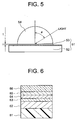
- Figure 5 shows an arrangement of the optical recording medium of the present embodiment and an optical part (lens).
- an optical disk 51 comprises a substrate 52 on which are formed stacked layers 53 including a recording layer.
- An SIL 54 is arranged at the stacked layer 53 side of the optical disk 51.
- the distance t between the surface of the stacked layers 53 and the SIL 54 is extremely narrow, usually 200 nm or less. Since light collected by an objective lens (not shown) enters the SIL 54, the NA becomes high. Also, ⁇ represents the incident angle of the light focused on the optical disk 51.
- Figure 6 is a cross-sectional view of the optical recording medium of the present embodiment.
- the present embodiment is assumed as a phase change type optical disk used for light of a wavelength of 650 nm.
- the optical disk shown in Fig. 6 is structured with a reflective layer 62, a second dielectric layer 63, a recording layer 64, and a first dielectric layer 65 sequentially stacked on a substrate 61 and, further, a heat radiating layer 66 formed on them.
- laser light is focused from the side at which the heat radiating layer 66 is formed.
- the laser light strikes the optical disk with the line passing through the center of the beam diameter (beam waist) perpendicular to the surface of the disk.
- the five layers of the heat radiating layer 66, the first dielectric layer 65, the recording layer 64, the second dielectric layer 63, and the reflective layer 62 satisfy an enhancement condition of the light perpendicularly striking the disk surface (perpendicularly incident component).
- the design is optimized for obtaining good signal characteristics for the perpendicularly incident component.
- the reflective layer 62 for example, an Al-alloy layer of a thickness of 120 nm is used.
- a plastic substrate comprised of polycarbonate (PC) or polymethyl methacrylate (PMMA) and other acryl-based resins and a glass substrate etc. may be used.
- PC polycarbonate
- PMMA polymethyl methacrylate
- the reflective layer 62 on the substrate 61 for example an Al layer or Al-alloy layer is used.
- the thickness of the reflective layer 62 is set at, for example, about 50 to 200 nm.
- the reflective layer 62 not only reflects the light focused on the optical disk, but also functions to promote the dispersion of heat from the recording layer 64. While the temperature of the recording layer 64 rises due to absorption of light, the reflective layer 62 has a high heat conductivity since it is usually composed of a metal layer and acts as a kind of heat sink.
- the material of the reflective layer 62 as long as the material has a predetermined reflectance and heat conductivity, it is also possible to use a semimetal, a compound of metal or semimetal, and semiconductors and their compounds in addition to metal.
- the second dielectric layer 63 functions as a protective layer of the phase changing recording layer 64.
- the second dielectric layer 63 need not necessarily be formed, for example, when not rewriting on the optical disk and in other cases.
- chalcogens or chalcogen compounds specifically, a system including Te, Se, Ge-Te, Ge-Sb-Te, Ge-Te Sb-Te, In-Sb-Te, Ag-In-Sb-Te, Au-In-Sb-Te, Ge-Sb-Te-Se, In-Sb-Se, Bi-Te, Bi-Se, Sb-Se, Sb-Te, Ge-Sb-Te-Bi, Ge-Sb-Te-Co, Ge-Sb-Te-Au, Zn-Ge-In-Sb-Te, or such a system doped with nitrogen, oxygen, or another gas additive or doped with Pd can be mentioned.
- the first dielectric layer 65 on the recording layer 64 functions as a protective layer of the phase changing recording layer 64.
- a material having a higher heat conductivity than the first dielectric layer 65 is used.
- a material having a heat conductivity of almost 0.1 (W/cm ⁇ K) or more and a quenching coefficient k of less than 0.1 with respect to the laser light used for recording and/or reproducing is preferably used.
- BN, SiN, SiC, Ta 2 O 5 , diamond-state carbon, and mixtures of these can be preferably used as the material of the heat radiating layer 66, in addition to Al described above.
- the thickness of the heat radiating layer 66 is appropriately set within a range where the heat radiating layer 66 has transparency.
- the heat radiating layer having a high heat conductivity is formed between the recording layer of the disk and the optical system, the temperature rise at the disk surface due to the focusing of laser light can be prevented. Due to this, it is made possible to maintain signals recorded on the optical disk and prevent damage to the optical disk by heat.
- the optical recording medium of the present embodiment since a layer composed of AlN or another inorganic material is formed at the outermost layer of the disk as the heat radiating layer 66, the surface hardness is high and the recording layer of the optical disk is not easily damaged when the head or optical system and the disk collide.
- the heat radiating layer 66 is formed covering the disk surface, ablation of the disk material is prevented and destruction of the film along with the elapse of time due to ablation can be prevented.
- the optical recording device of the present invention can be configured.
- Figure 7 shows the results of calculating the temperature rise in the phase change type optical disk of the above first embodiment due to focusing of laser light.
- the temperature of the recording layer is plotted against the time after the focusing of the laser light.
- the disk surface was made the x-y plane
- the beam spot was made the origin O
- the direction of the optical axis of the laser light was made the z-axis (see Fig. 4B).
- the direction x of beam travel is the direction of relative movement of the beam spot on the disk along with disk rotation. Therefore, y corresponds to the distance from the beam spot in the direction of disk radius.
- the calculation was performed setting y as 0 nm, 300 nm and 500 nm.
- the intensity of the laser light was presumed to be 0.2 mW or the same level as the reproducing light.
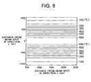
- Figure 8 shows the results of calculating the dispersion of heat from a recording mark on which laser light is focused to directions in the disk plane (laser scanning direction or disk radius direction) in the phase change type optical disk of the above first embodiment.
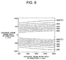
- the results of calculation of the case of the configuration where the heat radiating layer 66 is not formed is shown in Fig. 9.
- the film configuration in the conventional structure is made the same as the comparative example described above (the conditions used for the calculation of Fig. 4A).
- Figure 8 and Fig. 9 correspond to top views of the heat distribution of an optical disk.
- the dispersion of heat in the disk radius direction is suppressed by the film configuration of the present embodiment. That is, in the case of the present embodiment, dispersion of heat in a direction perpendicular to the disk surface is promoted.
- the optical disk of the present embodiment when laser light is focused on any recording mark, it is possible to prevent erasure of the recording mark formed in the next track, so-called, "cross write". Due to this, it is made possible to reduce the space between tracks and improve the recording density.
- the heat radiating layer of the above optical disk of the present invention can also be a multilayer structure.
- stacked layers comprised of a plurality of materials having extremely close optical constants and having different heat constants as the heat radiating layer, it is possible, in design, to control only the heat characteristics as desired while not changing the optical characteristics of the optical recording medium.
- an antireflection film comprising for example a silicon oxide layer, silicon nitride layer, and silicon oxide layer sequentially stacked on each other.
- an antireflection film as described above can be formed between the first dielectric layer 65 and the heat radiating layer 66.
- an antireflection coating on the surface of the lens becomes unnecessary. Due to this, it is possible to prevent damage to the antireflection coating on the lens surface caused by contact of the optical recording medium and the lens etc. and the damage to the electric characteristics during recording and reproduction from the lens surface.
- optical recording medium and the optical recording and reproduction device of the present invention are not limited to the above explanation.
- a layer of for example TbFeCo amorphous alloy or another material able to be changed in the magnetization state by using focusing of laser light it is also possible to apply the present invention to a magneto-optical disk.
- the optical recording medium of the present invention can be either rewritable or read-only.
- the optical recording medium of the present invention it is possible to prevent heat buildup in the optical recording medium due to focusing of laser light and the consequent erasure of signals recorded on the optical recording medium and damage to the optical recording medium.
- the optical recording and reproduction device of the present invention it is possible to prevent heat buildup in the optical recording medium due to focusing of laser light and the consequent erasure of signals recorded on the optical recording medium and damage to the optical recording medium.
- optical recording medium of the present invention it is possible to prevent damage due to collision with an optical system.
- optical recording and reproduction device of the present invention it is possible to prevent damage due to collision with an optical system.
Landscapes
- Engineering & Computer Science (AREA)
- Chemical & Material Sciences (AREA)
- Physics & Mathematics (AREA)
- Nanotechnology (AREA)
- Mathematical Physics (AREA)
- Theoretical Computer Science (AREA)
- Crystallography & Structural Chemistry (AREA)
- Inorganic Chemistry (AREA)
- Optics & Photonics (AREA)
- Optical Record Carriers And Manufacture Thereof (AREA)
- Optical Recording Or Reproduction (AREA)
Applications Claiming Priority (2)
| Application Number | Priority Date | Filing Date | Title |
|---|---|---|---|
| JP19674699 | 1999-07-09 | ||
| JP11196746A JP2001023245A (ja) | 1999-07-09 | 1999-07-09 | 光記録媒体および光記録装置 |
Publications (3)
| Publication Number | Publication Date |
|---|---|
| EP1067533A2 true EP1067533A2 (de) | 2001-01-10 |
| EP1067533A3 EP1067533A3 (de) | 2004-04-28 |
| EP1067533B1 EP1067533B1 (de) | 2006-04-05 |
Family
ID=16362928
Family Applications (1)
| Application Number | Title | Priority Date | Filing Date |
|---|---|---|---|
| EP00113807A Expired - Lifetime EP1067533B1 (de) | 1999-07-09 | 2000-06-29 | Optisches Aufzeichnungsmedium und optisches Aufzeichnungs- und Wiedergabegerät |
Country Status (4)
| Country | Link |
|---|---|
| US (2) | US6934224B1 (de) |
| EP (1) | EP1067533B1 (de) |
| JP (1) | JP2001023245A (de) |
| DE (1) | DE60027089T2 (de) |
Cited By (4)
| Publication number | Priority date | Publication date | Assignee | Title |
|---|---|---|---|---|
| KR20030004747A (ko) * | 2001-07-06 | 2003-01-15 | 엘지전자 주식회사 | 근접장용 광 디스크의 적층구조 |
| KR20030037753A (ko) * | 2001-11-05 | 2003-05-16 | 엘지전자 주식회사 | 근접장용 광디스크 구조 |
| EP1302940A3 (de) * | 2001-10-09 | 2003-09-17 | Pioneer Corporation | Optisches Aufzeichnungsmedium |
| EP1128374A3 (de) * | 2000-02-21 | 2008-04-02 | Sony Corporation | Optisches Aufzeichnungsmedium, optisches Abtastgerät und optisches Aufzeichnungs- und/oder Wiedergabegerät |
Families Citing this family (6)
| Publication number | Priority date | Publication date | Assignee | Title |
|---|---|---|---|---|
| US7058000B2 (en) * | 2000-12-08 | 2006-06-06 | Sony Corporation | Information recording disc having an anti-reflection layer and information recording/reproducing apparatus |
| US7241549B2 (en) * | 2001-09-18 | 2007-07-10 | Ricoh Company, Ltd. | Information recording medium |
| JP2003217174A (ja) * | 2002-01-21 | 2003-07-31 | Pioneer Electronic Corp | グルーブ間記録方式による光ディスク |
| JP2004220699A (ja) * | 2003-01-15 | 2004-08-05 | Tdk Corp | 光記録媒体 |
| JP4078237B2 (ja) * | 2003-03-28 | 2008-04-23 | Tdk株式会社 | 光記録媒体、光記録方法及び光記録装置 |
| JP4354733B2 (ja) * | 2003-04-18 | 2009-10-28 | Tdk株式会社 | 光記録媒体 |
Family Cites Families (45)
| Publication number | Priority date | Publication date | Assignee | Title |
|---|---|---|---|---|
| JPS6124041A (ja) * | 1984-07-13 | 1986-02-01 | Canon Inc | 光学的磁気記録媒体 |
| US4794560A (en) * | 1985-09-30 | 1988-12-27 | International Business Machines Corporation | Eraseable self biasing thermal magneto-optic medium |
| CA2000597C (en) | 1988-10-21 | 1995-07-11 | Toshio Ishikawa | Optical recording element |
| US5272684A (en) * | 1989-08-01 | 1993-12-21 | Mitsubishi Denki Kabushiki Kaisha | Information recording method and information recording apparatus for magneto-optic recording information medium |
| US5272667A (en) * | 1989-12-29 | 1993-12-21 | Matsushita Electric Industrial Co., Ltd. | Optical information recording apparatus for recording optical information in a phase change type optical recording medium and method therefor |
| JP3069149B2 (ja) | 1990-07-09 | 2000-07-24 | 株式会社リコー | 光情報記録媒体 |
| US5234737A (en) | 1991-01-28 | 1993-08-10 | Fuji Xerox Co., Ltd. | Phase change optical recording medium |
| JPH04326311A (ja) | 1991-04-26 | 1992-11-16 | Sony Corp | 光導波路端面結合装置 |
| JPH05151619A (ja) | 1991-10-01 | 1993-06-18 | Ricoh Co Ltd | 光情報記録媒体及び記録方法 |
| JPH05144082A (ja) * | 1991-11-26 | 1993-06-11 | Matsushita Electric Ind Co Ltd | 光記録媒体と光記録媒体用保護膜 |
| EP0564260B1 (de) * | 1992-03-30 | 2000-09-06 | Kabushiki Kaisha Toshiba | Optisches Aufzeichnungsmedium und optisches Aufzeichnungs/Wiedergabegerät |
| JP3287648B2 (ja) * | 1993-06-07 | 2002-06-04 | 株式会社リコー | 相変化型情報記録媒体の記録同時ベリファイ方法及び相変化型情報記録ドライブ装置 |
| US5596564A (en) * | 1993-10-08 | 1997-01-21 | Matsushita Electric Industrial Co., Ltd. | Information recording medium and apparatus and method for recording and reproducing information |
| US5631056A (en) * | 1994-03-31 | 1997-05-20 | Victor Company Of Japan, Ltd. | Optical recording medium |
| US5809201A (en) * | 1994-06-24 | 1998-09-15 | Mitsubishi Denki Kabushiki Kaisha | Specially formatted optical disk and method of playback |
| US5778142A (en) * | 1994-11-24 | 1998-07-07 | Kabushiki Kaisha Toshiba | Large capacity recording medium, method and apparatus for reproducing data from a large-capacity recording medium, and method and apparatus for recording data on a large-capacity recording medium |
| FR2730990B1 (fr) * | 1995-02-23 | 1997-04-04 | Saint Gobain Vitrage | Substrat transparent a revetement anti-reflets |
| TW430785B (en) * | 1995-04-14 | 2001-04-21 | Toshiba Corp | Interactively broadcasting recording-media and its regeneration system |
| TW329515B (en) * | 1995-10-24 | 1998-04-11 | Matsushita Electric Industrial Co Ltd | Recording medium and reproduction apparatus |
| JP3748936B2 (ja) * | 1996-03-18 | 2006-02-22 | パイオニア株式会社 | 情報記録装置及び方法並びに情報再生装置及び方法 |
| US6757483B1 (en) * | 1996-03-19 | 2004-06-29 | Pioneer Electronic Corporation | Information recording medium with aggregate attribute information recorded in video manager, apparatus for recording the same and apparatus for reproducing the same |
| JPH10162443A (ja) * | 1996-12-02 | 1998-06-19 | Sanyo Electric Co Ltd | 情報再生装置 |
| US6381403B1 (en) * | 1997-01-31 | 2002-04-30 | Victor Company Of Japan, Ltd. | Audio disk of improved data structure and reproduction apparatus thereof |
| US6449227B1 (en) * | 1997-03-25 | 2002-09-10 | Samsung Electronics Co., Ltd. | DVD-audio disk, and apparatus and method for playing the same |
| JPH117657A (ja) * | 1997-04-21 | 1999-01-12 | Hitachi Maxell Ltd | 光記録媒体、光ヘッド及び光記録装置 |
| US6217968B1 (en) | 1997-04-21 | 2001-04-17 | Hitachi Maxell, Ltd. | Optical recording medium, optical head and optical recording device |
| US6636474B1 (en) * | 1997-07-16 | 2003-10-21 | Victor Company Of Japan, Ltd. | Recording medium and audio-signal processing apparatus |
| TW497094B (en) | 1997-08-07 | 2002-08-01 | Hitachi Maxell | Optical recording medium and optical recording device |
| JPH11110822A (ja) * | 1997-08-08 | 1999-04-23 | Tdk Corp | 光記録媒体およびその記録再生方法 |
| US6231945B1 (en) * | 1997-09-09 | 2001-05-15 | Hitachi, Ltd. | Information recording medium |
| JPH11126387A (ja) * | 1997-10-20 | 1999-05-11 | Sanyo Electric Co Ltd | 光磁気記録媒体 |
| CN1319051C (zh) * | 1997-11-21 | 2007-05-30 | 日本胜利株式会社 | 音频信号的编码装置、唱盘以及盘重放装置 |
| US6738561B1 (en) * | 1997-11-21 | 2004-05-18 | Victor Company Of Japan, Ltd. | Recording medium and signal processing apparatus |
| CN1133996C (zh) * | 1997-11-22 | 2004-01-07 | 三星电子株式会社 | 反射折射光学系统、采用该系统的光拾取器、光盘驱动器 |
| JPH11195243A (ja) * | 1997-12-26 | 1999-07-21 | Sony Corp | 多層光ディスク及び記録再生装置 |
| JPH11240252A (ja) * | 1997-12-22 | 1999-09-07 | Tdk Corp | 光記録媒体 |
| JPH11203725A (ja) * | 1998-01-16 | 1999-07-30 | Nec Corp | 相変化光ディスク |
| DE69928190T2 (de) | 1998-02-24 | 2006-07-27 | Sony Corp. | Optisches aufzeichnungsmedium |
| JPH11265563A (ja) * | 1998-03-16 | 1999-09-28 | Pioneer Electron Corp | 情報記録媒体及び情報再生装置 |
| JPH11296997A (ja) * | 1998-04-10 | 1999-10-29 | Pioneer Electron Corp | 情報記録媒体及び再生装置 |
| JP3090118B2 (ja) * | 1998-05-08 | 2000-09-18 | 日本電気株式会社 | 光学情報記録媒体 |
| US6069853A (en) * | 1998-08-21 | 2000-05-30 | Terastor Corporation | Head including a heating element for reducing signal distortion in data storage systems |
| JP2000076703A (ja) * | 1998-08-28 | 2000-03-14 | Ricoh Co Ltd | 光記録媒体 |
| US6449239B1 (en) * | 1998-11-25 | 2002-09-10 | Matsushita Electric Industrial Co., Ltd. | Optical information recording medium with thermal diffusion layer |
| JP2000207792A (ja) | 1999-01-08 | 2000-07-28 | Sony Corp | 光磁気記録媒体、光学ヘッドおよび記録再生装置 |
-
1999
- 1999-07-09 JP JP11196746A patent/JP2001023245A/ja active Pending
-
2000
- 2000-06-29 DE DE60027089T patent/DE60027089T2/de not_active Expired - Lifetime
- 2000-06-29 EP EP00113807A patent/EP1067533B1/de not_active Expired - Lifetime
- 2000-06-29 US US09/606,885 patent/US6934224B1/en not_active Expired - Fee Related
-
2005
- 2005-04-01 US US11/095,510 patent/US7123551B2/en not_active Expired - Fee Related
Cited By (5)
| Publication number | Priority date | Publication date | Assignee | Title |
|---|---|---|---|---|
| EP1128374A3 (de) * | 2000-02-21 | 2008-04-02 | Sony Corporation | Optisches Aufzeichnungsmedium, optisches Abtastgerät und optisches Aufzeichnungs- und/oder Wiedergabegerät |
| KR20030004747A (ko) * | 2001-07-06 | 2003-01-15 | 엘지전자 주식회사 | 근접장용 광 디스크의 적층구조 |
| EP1302940A3 (de) * | 2001-10-09 | 2003-09-17 | Pioneer Corporation | Optisches Aufzeichnungsmedium |
| US6828000B2 (en) | 2001-10-09 | 2004-12-07 | Pioneer Corporation | Optical recording medium |
| KR20030037753A (ko) * | 2001-11-05 | 2003-05-16 | 엘지전자 주식회사 | 근접장용 광디스크 구조 |
Also Published As
| Publication number | Publication date |
|---|---|
| US20050180307A1 (en) | 2005-08-18 |
| DE60027089T2 (de) | 2006-09-21 |
| JP2001023245A (ja) | 2001-01-26 |
| US7123551B2 (en) | 2006-10-17 |
| EP1067533A3 (de) | 2004-04-28 |
| DE60027089D1 (de) | 2006-05-18 |
| US6934224B1 (en) | 2005-08-23 |
| EP1067533B1 (de) | 2006-04-05 |
Similar Documents
| Publication | Publication Date | Title |
|---|---|---|
| US6160769A (en) | Optical recording medium and optical recording device | |
| CA2022005C (en) | Optical recording apparatus | |
| US6552968B1 (en) | Optical recording medium, method of producing same, and optical recording and reproduction device | |
| JPH09326136A (ja) | 光記録媒体及びその製造方法 | |
| US5631895A (en) | Optical information recording medium | |
| US6787211B2 (en) | Optical recording medium and its manufacturing method | |
| EP1067533B1 (de) | Optisches Aufzeichnungsmedium und optisches Aufzeichnungs- und Wiedergabegerät | |
| EP0977192A1 (de) | Optisches aufzeichnungsgerät und optisches aufzeichnungsmedium | |
| US6683846B2 (en) | Information recording disc having an anti-reflection layer and information recording/reproducing apparatus | |
| JP4265861B2 (ja) | 光学読み取り・書き込み方法、情報記録媒体、及び光学装置 | |
| EP1543505A1 (de) | Hochdichtes aufzeichnungsmedium mit superauflösender nahfeldstruktur, hergestellt unter verwendung einer metalloxid-oder siliziumoxid-maskenschicht mit hohem schmelzpunkt | |
| US6967050B2 (en) | Optical recording medium and a method of manufacturing the same | |
| KR20020002431A (ko) | 광 기록 매체 및 이를 사용하는 방법 | |
| US8325586B2 (en) | Rewritable optical record carrier | |
| US7058000B2 (en) | Information recording disc having an anti-reflection layer and information recording/reproducing apparatus | |
| US20040264333A1 (en) | [method of reading data from high density optical recording medium] | |
| JP2001023241A (ja) | 光記録媒体およびその製造方法と、光記録装置 | |
| WO2008088119A1 (en) | Super resolution optical recording medium | |
| JPH1173682A (ja) | 光記録媒体、光ヘッド及び光記録装置 | |
| KR19990006606A (ko) | 광학적 데이터 기록 매체 | |
| JP2001331972A (ja) | 光情報記録媒体 | |
| JP2002251785A (ja) | 光情報記録媒体 | |
| JPH11353711A (ja) | 光ディスク | |
| JP2002251787A (ja) | 光情報記録媒体 | |
| JPH11120594A (ja) | 光ディスクの初期化方法及び光ディスクの初期化装置 |
Legal Events
| Date | Code | Title | Description |
|---|---|---|---|
| PUAI | Public reference made under article 153(3) epc to a published international application that has entered the european phase |
Free format text: ORIGINAL CODE: 0009012 |
|
| AK | Designated contracting states |
Kind code of ref document: A2 Designated state(s): AT BE CH CY DE DK ES FI FR GB GR IE IT LI LU MC NL PT SE |
|
| AX | Request for extension of the european patent |
Free format text: AL;LT;LV;MK;RO;SI |
|
| PUAL | Search report despatched |
Free format text: ORIGINAL CODE: 0009013 |
|
| AK | Designated contracting states |
Kind code of ref document: A3 Designated state(s): AT BE CH CY DE DK ES FI FR GB GR IE IT LI LU MC NL PT SE |
|
| AX | Request for extension of the european patent |
Extension state: AL LT LV MK RO SI |
|
| 17P | Request for examination filed |
Effective date: 20040830 |
|
| 17Q | First examination report despatched |
Effective date: 20041005 |
|
| AKX | Designation fees paid |
Designated state(s): DE FR GB |
|
| GRAP | Despatch of communication of intention to grant a patent |
Free format text: ORIGINAL CODE: EPIDOSNIGR1 |
|
| GRAS | Grant fee paid |
Free format text: ORIGINAL CODE: EPIDOSNIGR3 |
|
| GRAA | (expected) grant |
Free format text: ORIGINAL CODE: 0009210 |
|
| AK | Designated contracting states |
Kind code of ref document: B1 Designated state(s): DE FR GB |
|
| REG | Reference to a national code |
Ref country code: GB Ref legal event code: FG4D |
|
| REF | Corresponds to: |
Ref document number: 60027089 Country of ref document: DE Date of ref document: 20060518 Kind code of ref document: P |
|
| ET | Fr: translation filed | ||
| PLBE | No opposition filed within time limit |
Free format text: ORIGINAL CODE: 0009261 |
|
| STAA | Information on the status of an ep patent application or granted ep patent |
Free format text: STATUS: NO OPPOSITION FILED WITHIN TIME LIMIT |
|
| 26N | No opposition filed |
Effective date: 20070108 |
|
| REG | Reference to a national code |
Ref country code: GB Ref legal event code: 746 Effective date: 20091130 |
|
| PGFP | Annual fee paid to national office [announced via postgrant information from national office to epo] |
Ref country code: FR Payment date: 20110630 Year of fee payment: 12 |
|
| PGFP | Annual fee paid to national office [announced via postgrant information from national office to epo] |
Ref country code: GB Payment date: 20110620 Year of fee payment: 12 |
|
| PGFP | Annual fee paid to national office [announced via postgrant information from national office to epo] |
Ref country code: DE Payment date: 20110622 Year of fee payment: 12 |
|
| GBPC | Gb: european patent ceased through non-payment of renewal fee |
Effective date: 20120629 |
|
| REG | Reference to a national code |
Ref country code: FR Ref legal event code: ST Effective date: 20130228 |
|
| REG | Reference to a national code |
Ref country code: DE Ref legal event code: R119 Ref document number: 60027089 Country of ref document: DE Effective date: 20130101 |
|
| PG25 | Lapsed in a contracting state [announced via postgrant information from national office to epo] |
Ref country code: DE Free format text: LAPSE BECAUSE OF NON-PAYMENT OF DUE FEES Effective date: 20130101 Ref country code: FR Free format text: LAPSE BECAUSE OF NON-PAYMENT OF DUE FEES Effective date: 20120702 Ref country code: GB Free format text: LAPSE BECAUSE OF NON-PAYMENT OF DUE FEES Effective date: 20120629 |