EP1067628A2 - Antenne für mehrere Frequenzen - Google Patents
Antenne für mehrere Frequenzen Download PDFInfo
- Publication number
- EP1067628A2 EP1067628A2 EP00660123A EP00660123A EP1067628A2 EP 1067628 A2 EP1067628 A2 EP 1067628A2 EP 00660123 A EP00660123 A EP 00660123A EP 00660123 A EP00660123 A EP 00660123A EP 1067628 A2 EP1067628 A2 EP 1067628A2
- Authority
- EP
- European Patent Office
- Prior art keywords
- antenna
- whip
- whip antenna
- pifa
- dielectric
- Prior art date
- Legal status (The legal status is an assumption and is not a legal conclusion. Google has not performed a legal analysis and makes no representation as to the accuracy of the status listed.)
- Granted
Links
Images

Classifications
-
- H—ELECTRICITY
- H01—ELECTRIC ELEMENTS
- H01Q—ANTENNAS, i.e. RADIO AERIALS
- H01Q5/00—Arrangements for simultaneous operation of antennas on two or more different wavebands, e.g. dual-band or multi-band arrangements
-
- H—ELECTRICITY
- H01—ELECTRIC ELEMENTS
- H01Q—ANTENNAS, i.e. RADIO AERIALS
- H01Q1/00—Details of, or arrangements associated with, antennas
- H01Q1/12—Supports; Mounting means
- H01Q1/22—Supports; Mounting means by structural association with other equipment or articles
- H01Q1/24—Supports; Mounting means by structural association with other equipment or articles with receiving set
- H01Q1/241—Supports; Mounting means by structural association with other equipment or articles with receiving set used in mobile communications, e.g. GSM
- H01Q1/242—Supports; Mounting means by structural association with other equipment or articles with receiving set used in mobile communications, e.g. GSM specially adapted for hand-held use
- H01Q1/243—Supports; Mounting means by structural association with other equipment or articles with receiving set used in mobile communications, e.g. GSM specially adapted for hand-held use with built-in antennas
- H01Q1/244—Supports; Mounting means by structural association with other equipment or articles with receiving set used in mobile communications, e.g. GSM specially adapted for hand-held use with built-in antennas extendable from a housing along a given path
-
- H—ELECTRICITY
- H01—ELECTRIC ELEMENTS
- H01Q—ANTENNAS, i.e. RADIO AERIALS
- H01Q5/00—Arrangements for simultaneous operation of antennas on two or more different wavebands, e.g. dual-band or multi-band arrangements
- H01Q5/30—Arrangements for providing operation on different wavebands
- H01Q5/307—Individual or coupled radiating elements, each element being fed in an unspecified way
- H01Q5/342—Individual or coupled radiating elements, each element being fed in an unspecified way for different propagation modes
- H01Q5/357—Individual or coupled radiating elements, each element being fed in an unspecified way for different propagation modes using a single feed point
-
- H—ELECTRICITY
- H01—ELECTRIC ELEMENTS
- H01Q—ANTENNAS, i.e. RADIO AERIALS
- H01Q9/00—Electrically-short antennas having dimensions not more than twice the operating wavelength and consisting of conductive active radiating elements
- H01Q9/04—Resonant antennas
- H01Q9/0407—Substantially flat resonant element parallel to ground plane, e.g. patch antenna
- H01Q9/0421—Substantially flat resonant element parallel to ground plane, e.g. patch antenna with a shorting wall or a shorting pin at one end of the element
-
- H—ELECTRICITY
- H01—ELECTRIC ELEMENTS
- H01Q—ANTENNAS, i.e. RADIO AERIALS
- H01Q9/00—Electrically-short antennas having dimensions not more than twice the operating wavelength and consisting of conductive active radiating elements
- H01Q9/04—Resonant antennas
- H01Q9/30—Resonant antennas with feed to end of elongated active element, e.g. unipole
Definitions
- the invention relates to a whip antenna construction having at least two operating frequency bands.
- GSM Global System for Mobile telecommunications
- DCS1800 Digital Cellular System
- JDC Japanese Digital Cellular
- PCN personal Communication Network
- PCS Personal Communication System
- DECT Digital European Cordless Telephone
- UMTS Universal Mobile Communication System
- Mobile communications apparatus use various antenna constructions, such as e.g. whip antennas, cylindrical coil or helix antennas and planar inverted-F antennas (PIFA).
- the resonance frequency of an antenna is determined on the basis of its electrical length, which is advantageously ⁇ /2, 3 ⁇ /8, 5 ⁇ /8 or ⁇ /4, where ⁇ is the wavelength applied.
- ⁇ is the wavelength applied.
- one and the same basic antenna has in principle several frequency bands that can be used.
- the drawback is that these frequency bands seldom falls on the bands of the two desired networks. From the prior art it is also known different combined antennas that can function in two frequency ranges: a combined helix and whip antenna, and a combined PIFA and whip antenna, for example.
- the whip antenna when pulled out, functions at the lower operating frequency and the other part of the antenna construction functions at the upper operating frequency.
- the disadvantage of the helix-whip combination is the protrusion caused by the helix part which is inconvenient when the communications apparatus is placed in a pocket, for example.
- the disadvantage of the PIFA-whip combination is that the user's hand may almost completely cover the PIFA, located inside the housing of the phone, thus considerably degrading the operation of the PIFA.
- An object of this invention is to reduce said disadvantages of dual-frequency antennas according to the prior art.
- the antenna according to the invention is characterized by what is expressed in the independent claim. Preferred embodiments of the invention are presented in the other claims.
- the basic idea of the invention is as follows: A dielectric block with a relatively high permittivity is added to the whip antenna, at a point where there is a voltage maximum at a harmonic frequency of the basic resonance frequency of the antenna.
- the dielectric medium causes the harmonic frequency in question to shift downwards.
- the arrangement is realized such that the basic resonance frequency of the whip antenna falls on the operating frequency band of one network and the harmonic frequency in question falls on the operating frequency band of the other network.
- the construction may further comprise a PIFA that operates in the corresponding operating frequency bands according to the systems.
- An advantage of the invention is that a single whip antenna can be used in two desired frequency bands when the antenna is in the pulled-out position. Another advantage of the invention is that when the whip antenna according to the invention is used together with a PIFA, the degradation of the operation of the PIFA caused by the user's hand will not substantially degrade the connection since the whip, too, operates in the operating frequency of the PIFA. A further advantage of the invention is that the manufacturing costs of the construction according to the invention are relatively low.
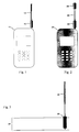
- Fig. 1 shows an example of the whip antenna arrangement according to the invention. It shows a mobile station 11 with its whip antenna 12 in the pulled-out position, said antenna being a quarter-wave antenna.
- a dielectric block 13 shaped like a cylindrical ring.
- the electrical length of the antenna is increased at the harmonic frequency in question and, consequently, the harmonic resonance frequency is decreased from what it would be without the dielectric block.
- the amount of change of the frequency of a harmonic is directly proportional to the permittivity of the dielectric block 13 used.
- the greater the dielectric constant ⁇ r the greater the change of the frequency of the harmonic.
- the length of block 13 in the direction of the axis of the antenna is, say, 10 mm and the thickness of the wall is, say, 1 mm
- a material may be needed the dielectric constant ⁇ r of which is several tens.
- Such values of ⁇ r can be achieved with various ceramic materials. They, however, have the drawback of being relatively rigid and brittle.
- Commercial plastic materials which would be suited to being placed around the whip antenna because of their elasticity, have a dielectric constant ⁇ r of about 10. This value is too low in practice if there is one dielectric block as shown in Fig. 1.
- Fig. 2 shows an example of the whip antenna construction according to the invention in which the dielectric material can be plastic even if the harmonic frequency should be shifted a relatively great amount.
- Fig. 2 shows a mobile station 21 with its whip antenna 22 in the pulled-out position, said antenna being a quarter-wave antenna in this case, too.
- a dielectric block 23 shaped like a cylindrical ring.
- a second dielectric block 24 At the outer end of the whip antenna there is installed a second dielectric block 24.
- the first dielectric block 23 is dimensioned such that the voltage maximum at the already-changed harmonic frequency caused by first dielectric block falls on the tip of the whip antenna.
- the harmonic frequency in question is further decreased.
- the ⁇ r required of the dielectric blocks 23, 24 is not as great as in the construction of Fig. 1. In this preferred embodiment it is possible to use commercial plastics currently available.
- the method described above can be extended in accordance with the invention in such a manner that after the two dielectric blocks have been positioned, a new voltage maximum location is searched where a third dielectric block will be positioned. In principle, this can be repeated until the desired operating frequencies have been achieved.
- Fig. 3 shows an example of the combination of a whip antenna and PIFA in accordance with the invention.
- the arrangement comprises a PIFA 34 operating at one or more frequencies, a whip antenna 32 and a dielectric block 33 around the latter.
- the block 33 is installed in a fixed manner.
- the whip antenna may be fixed or it may be one that can be pushed inside the communications apparatus, in which case the whip antenna has a first and a second extreme position. If the movable whip is in the pushed-in position, only the PIFA 34 functions as the antenna of the communications apparatus.
- the dielectric block 33 is at a location of the whip antenna where the harmonic resonance frequency of the antenna gets the desired value according to the description of Fig. 1.
- the whip antenna functions at two desired frequency bands which are advantageously the same as the operating frequency bands of the PIFA.
- the whip antenna according to the invention improves the function of the antenna of a mobile phone especially in poor and noisy conditions in which the performance of the PIFA proper becomes insufficient. Furthermore, the degrading effect of the user's hand on the function of the antenna is reduced.
- the dielectric block 33 may be placed either below the radiating element of the PIFA, as in Fig. 3, or in its immediate vicinity. As the block 33 is then within the housing of the communications apparatus, its material can be some ceramic substance the ⁇ r of which is sufficient for the application in question.
- the dielectric block 33 in Fig. 3 as well as blocks 13, 23 and 24 in Figs. 1 and 2 are drawn thicker than the whip. In practice, however, they are realized such that their thickness equals that of the whip part.
- Fig. 4 shows an example of the reflection coefficient of a conventional ⁇ /4 whip antenna as a function of the frequency.
- the reflection coefficient S11 is given on the vertical axis in decibels; curve 41 represents its variation.
- the frequency scale on the horizontal axis extends from 400 to 2900 MHz.
- the reflection coefficient is -8.4 dB and -7.4 dB, respectively.
- f 1 and f 2 which are located in the band 824-894 MHz used by the analog AMPS (Advanced Mobile Phone Service) system.
- the reflection coefficient is -8.4 dB and -7.4 dB, respectively.
- These values mean the antenna can be used in the system.
- Another useable frequency band with the antenna would be around triple basic resonance frequency at 2.7 GHz, approximately. It is, however, of no use. For example, in a PCS cellular network, the operating frequency band of which is 1850-1990 MHz, the antenna would be useless because of mismatch.
- Fig. 5 shows by means of curve 51 the reflection coefficient of a ⁇ /4 whip antenna according to Fig. 1 as a function of the frequency.
- the whip antenna in this case, too, is originally dimensioned so as to be useable in an AMPS cellular network.
- the antenna now has a dielectric block such that the harmonic corresponding to the triple basic frequency of the antenna has now dropped somewhere near 2 GHz.
- the reflection coefficient is -3.6 dB and -11.1 dB, respectively. This means that the antenna functions acceptably almost throughout the whole PCS range.
- the operation is at least as good as with an antenna corresponding to Fig. 4; at measurement points f 1 and f 2 the reflection coefficient is -11.0 dB and -7.6 dB.
- whip antenna constructions can be realized on the basis of the inventional idea that can be used in frequency bands other than those two mentioned in said Figures.
- whip antennas can be realized in accordance with the invention that function in more than two operating frequency bands.
- the inventional idea can be applied in many ways within the scope defined by the claims attached hereto.
Landscapes
- Engineering & Computer Science (AREA)
- Computer Networks & Wireless Communication (AREA)
- Support Of Aerials (AREA)
- Waveguide Aerials (AREA)
- Details Of Aerials (AREA)
- Aerials With Secondary Devices (AREA)
- Variable-Direction Aerials And Aerial Arrays (AREA)
Applications Claiming Priority (2)
| Application Number | Priority Date | Filing Date | Title |
|---|---|---|---|
| FI991569 | 1999-07-08 | ||
| FI991569A FI112981B (fi) | 1999-07-08 | 1999-07-08 | Monitaajuusantenni |
Publications (3)
| Publication Number | Publication Date |
|---|---|
| EP1067628A2 true EP1067628A2 (de) | 2001-01-10 |
| EP1067628A3 EP1067628A3 (de) | 2003-07-09 |
| EP1067628B1 EP1067628B1 (de) | 2005-06-08 |
Family
ID=8555048
Family Applications (1)
| Application Number | Title | Priority Date | Filing Date |
|---|---|---|---|
| EP00660123A Expired - Lifetime EP1067628B1 (de) | 1999-07-08 | 2000-07-05 | Antenne für mehrere Frequenzen |
Country Status (5)
| Country | Link |
|---|---|
| US (1) | US6518925B1 (de) |
| EP (1) | EP1067628B1 (de) |
| AT (1) | ATE297600T1 (de) |
| DE (1) | DE60020643T2 (de) |
| FI (1) | FI112981B (de) |
Cited By (5)
| Publication number | Priority date | Publication date | Assignee | Title |
|---|---|---|---|---|
| WO2002043185A1 (de) * | 2000-11-22 | 2002-05-30 | Siemens Aktiengesellschaft | Antennensystem |
| RU2183888C1 (ru) * | 2000-10-19 | 2002-06-20 | Жастеро Трейдинг Лимитед | Способ увеличения действующей высоты малогабаритного антенного устройства и малогабаритное антенное устройство для осуществления способа |
| EP1061603A3 (de) * | 1999-06-14 | 2002-08-28 | Filtronic LK Oy | Antennenstruktur |
| WO2002067373A1 (en) * | 2001-02-16 | 2002-08-29 | Telefonaktiebolaget L.M. Ericsson (Publ) | Antenna systems including internal planar inverted-f antennas coupled with retractable antenna and wireless communicators incorporating same |
| WO2008118698A1 (en) * | 2007-03-23 | 2008-10-02 | Cisco Technology, Inc. | Multi-band-monopol-antenna |
Families Citing this family (33)
| Publication number | Priority date | Publication date | Assignee | Title |
|---|---|---|---|---|
| FI20055420A0 (fi) | 2005-07-25 | 2005-07-25 | Lk Products Oy | Säädettävä monikaista antenni |
| FI119009B (fi) * | 2005-10-03 | 2008-06-13 | Pulse Finland Oy | Monikaistainen antennijärjestelmä |
| FI118782B (fi) | 2005-10-14 | 2008-03-14 | Pulse Finland Oy | Säädettävä antenni |
| US8618990B2 (en) | 2011-04-13 | 2013-12-31 | Pulse Finland Oy | Wideband antenna and methods |
| FI20075269A0 (fi) * | 2007-04-19 | 2007-04-19 | Pulse Finland Oy | Menetelmä ja järjestely antennin sovittamiseksi |
| FI120427B (fi) | 2007-08-30 | 2009-10-15 | Pulse Finland Oy | Säädettävä monikaista-antenni |
| FI20096134A0 (fi) | 2009-11-03 | 2009-11-03 | Pulse Finland Oy | Säädettävä antenni |
| FI20096251A0 (sv) | 2009-11-27 | 2009-11-27 | Pulse Finland Oy | MIMO-antenn |
| US8847833B2 (en) * | 2009-12-29 | 2014-09-30 | Pulse Finland Oy | Loop resonator apparatus and methods for enhanced field control |
| FI20105158A7 (fi) | 2010-02-18 | 2011-08-19 | Pulse Finland Oy | Kuorisäteilijällä varustettu antenni |
| US9406998B2 (en) | 2010-04-21 | 2016-08-02 | Pulse Finland Oy | Distributed multiband antenna and methods |
| FI20115072A0 (fi) | 2011-01-25 | 2011-01-25 | Pulse Finland Oy | Moniresonanssiantenni, -antennimoduuli ja radiolaite |
| US8648752B2 (en) | 2011-02-11 | 2014-02-11 | Pulse Finland Oy | Chassis-excited antenna apparatus and methods |
| US9673507B2 (en) | 2011-02-11 | 2017-06-06 | Pulse Finland Oy | Chassis-excited antenna apparatus and methods |
| US8866689B2 (en) | 2011-07-07 | 2014-10-21 | Pulse Finland Oy | Multi-band antenna and methods for long term evolution wireless system |
| US9450291B2 (en) | 2011-07-25 | 2016-09-20 | Pulse Finland Oy | Multiband slot loop antenna apparatus and methods |
| US9123990B2 (en) | 2011-10-07 | 2015-09-01 | Pulse Finland Oy | Multi-feed antenna apparatus and methods |
| US9531058B2 (en) | 2011-12-20 | 2016-12-27 | Pulse Finland Oy | Loosely-coupled radio antenna apparatus and methods |
| US9484619B2 (en) | 2011-12-21 | 2016-11-01 | Pulse Finland Oy | Switchable diversity antenna apparatus and methods |
| US8988296B2 (en) | 2012-04-04 | 2015-03-24 | Pulse Finland Oy | Compact polarized antenna and methods |
| US9979078B2 (en) | 2012-10-25 | 2018-05-22 | Pulse Finland Oy | Modular cell antenna apparatus and methods |
| US10069209B2 (en) | 2012-11-06 | 2018-09-04 | Pulse Finland Oy | Capacitively coupled antenna apparatus and methods |
| US9647338B2 (en) | 2013-03-11 | 2017-05-09 | Pulse Finland Oy | Coupled antenna structure and methods |
| US10079428B2 (en) | 2013-03-11 | 2018-09-18 | Pulse Finland Oy | Coupled antenna structure and methods |
| US9634383B2 (en) | 2013-06-26 | 2017-04-25 | Pulse Finland Oy | Galvanically separated non-interacting antenna sector apparatus and methods |
| US9680212B2 (en) | 2013-11-20 | 2017-06-13 | Pulse Finland Oy | Capacitive grounding methods and apparatus for mobile devices |
| US9590308B2 (en) | 2013-12-03 | 2017-03-07 | Pulse Electronics, Inc. | Reduced surface area antenna apparatus and mobile communications devices incorporating the same |
| US9350081B2 (en) | 2014-01-14 | 2016-05-24 | Pulse Finland Oy | Switchable multi-radiator high band antenna apparatus |
| US9973228B2 (en) | 2014-08-26 | 2018-05-15 | Pulse Finland Oy | Antenna apparatus with an integrated proximity sensor and methods |
| US9948002B2 (en) | 2014-08-26 | 2018-04-17 | Pulse Finland Oy | Antenna apparatus with an integrated proximity sensor and methods |
| US9722308B2 (en) | 2014-08-28 | 2017-08-01 | Pulse Finland Oy | Low passive intermodulation distributed antenna system for multiple-input multiple-output systems and methods of use |
| US9906260B2 (en) | 2015-07-30 | 2018-02-27 | Pulse Finland Oy | Sensor-based closed loop antenna swapping apparatus and methods |
| CN114583436B (zh) * | 2020-11-30 | 2025-03-21 | 华为技术有限公司 | 一种电子设备 |
Family Cites Families (10)
| Publication number | Priority date | Publication date | Assignee | Title |
|---|---|---|---|---|
| DE2257352A1 (de) * | 1972-11-22 | 1974-05-30 | Kathrein Werke Kg | Fahrzeugantenne |
| DE9002022U1 (de) | 1990-02-21 | 1990-04-26 | Robert Bosch Gmbh, 70469 Stuttgart | Stabförmiger Strahler für mindestens zwei Frequenzbereiche |
| JPH057106A (ja) * | 1991-06-27 | 1993-01-14 | Harada Ind Co Ltd | 広帯域非接地型極超短波アンテナ |
| GB2257837B (en) * | 1991-07-13 | 1995-10-18 | Technophone Ltd | Retractable antenna |
| US5311201A (en) | 1991-09-27 | 1994-05-10 | Tri-Band Technologies, Inc. | Multi-band antenna |
| JP3243595B2 (ja) * | 1995-10-31 | 2002-01-07 | 株式会社トーキン | マルチバンドアンテナ及びそれを用いたマルチバンド携帯無線機 |
| FI110394B (fi) * | 1996-08-06 | 2003-01-15 | Filtronic Lk Oy | Yhdistelmäantenni |
| US6114996A (en) | 1997-03-31 | 2000-09-05 | Qualcomm Incorporated | Increased bandwidth patch antenna |
| US5943021A (en) | 1998-08-03 | 1999-08-24 | Ericsson Inc. | Swivel antenna with parasitic tuning |
| US6262693B1 (en) * | 1999-05-03 | 2001-07-17 | T&M Antennas | Snap fit compression antenna assembly |
-
1999
- 1999-07-08 FI FI991569A patent/FI112981B/fi active
-
2000
- 2000-07-05 AT AT00660123T patent/ATE297600T1/de not_active IP Right Cessation
- 2000-07-05 EP EP00660123A patent/EP1067628B1/de not_active Expired - Lifetime
- 2000-07-05 DE DE60020643T patent/DE60020643T2/de not_active Expired - Lifetime
- 2000-07-06 US US09/611,063 patent/US6518925B1/en not_active Expired - Fee Related
Cited By (6)
| Publication number | Priority date | Publication date | Assignee | Title |
|---|---|---|---|---|
| EP1061603A3 (de) * | 1999-06-14 | 2002-08-28 | Filtronic LK Oy | Antennenstruktur |
| RU2183888C1 (ru) * | 2000-10-19 | 2002-06-20 | Жастеро Трейдинг Лимитед | Способ увеличения действующей высоты малогабаритного антенного устройства и малогабаритное антенное устройство для осуществления способа |
| WO2002043185A1 (de) * | 2000-11-22 | 2002-05-30 | Siemens Aktiengesellschaft | Antennensystem |
| WO2002067373A1 (en) * | 2001-02-16 | 2002-08-29 | Telefonaktiebolaget L.M. Ericsson (Publ) | Antenna systems including internal planar inverted-f antennas coupled with retractable antenna and wireless communicators incorporating same |
| WO2008118698A1 (en) * | 2007-03-23 | 2008-10-02 | Cisco Technology, Inc. | Multi-band-monopol-antenna |
| US7515107B2 (en) | 2007-03-23 | 2009-04-07 | Cisco Technology, Inc. | Multi-band antenna |
Also Published As
| Publication number | Publication date |
|---|---|
| EP1067628B1 (de) | 2005-06-08 |
| DE60020643T2 (de) | 2006-05-04 |
| EP1067628A3 (de) | 2003-07-09 |
| ATE297600T1 (de) | 2005-06-15 |
| FI112981B (fi) | 2004-02-13 |
| FI991569L (fi) | 2001-01-09 |
| DE60020643D1 (de) | 2005-07-14 |
| US6518925B1 (en) | 2003-02-11 |
Similar Documents
| Publication | Publication Date | Title |
|---|---|---|
| US6518925B1 (en) | Multifrequency antenna | |
| EP1095422B1 (de) | Doppelbandantenne mit zwei gedruckten spiralelementen | |
| US6326921B1 (en) | Low profile built-in multi-band antenna | |
| KR100384656B1 (ko) | 기생 소자를 구비한 이중-대역 나선형 안테나 | |
| EP1212808B1 (de) | Halbeingebaute gedruckte multibandantenne | |
| US6614400B2 (en) | Antenna | |
| KR100612798B1 (ko) | 이동 단말기용 소형 인쇄된 나선형 안테나 | |
| US5504494A (en) | Multi-stage antenna | |
| US6611691B1 (en) | Antenna adapted to operate in a plurality of frequency bands | |
| AU749390B2 (en) | A portable electronic communication device with multi-band antenna system | |
| US6343208B1 (en) | Printed multi-band patch antenna | |
| EP1361623A1 (de) | Zwischen mehreren Frequenzbändern schaltbare Antenne für tragbare Endgeräte | |
| US6442400B1 (en) | Portable electronic communication device with dual-band antenna system | |
| WO2003096474A1 (en) | Multiple frequency bands switchable antenna for portable terminals | |
| US6127979A (en) | Antenna adapted to operate in a plurality of frequency bands | |
| EP1025612A1 (de) | Teleskopantenne für mehrbandbetrieb für mobiltelefon | |
| GB2335312A (en) | An antenna adapted to operate in a plurality of frequency bands | |
| EP1672733A1 (de) | Patchantenne | |
| WO2001011717A1 (en) | Antenna arrangement | |
| JP2001230617A (ja) | アンテナ | |
| WO2000077885A1 (en) | Antenna arrangement | |
| MXPA01006012A (en) | Printed multi-band patch antenna |
Legal Events
| Date | Code | Title | Description |
|---|---|---|---|
| PUAI | Public reference made under article 153(3) epc to a published international application that has entered the european phase |
Free format text: ORIGINAL CODE: 0009012 |
|
| AK | Designated contracting states |
Kind code of ref document: A2 Designated state(s): AT BE CH CY DE DK ES FI FR GB GR IE IT LI LU MC NL PT SE |
|
| AX | Request for extension of the european patent |
Free format text: AL;LT;LV;MK;RO;SI |
|
| PUAL | Search report despatched |
Free format text: ORIGINAL CODE: 0009013 |
|
| AK | Designated contracting states |
Designated state(s): AT BE CH CY DE DK ES FI FR GB GR IE IT LI LU MC NL PT SE |
|
| AX | Request for extension of the european patent |
Extension state: AL LT LV MK RO SI |
|
| 17P | Request for examination filed |
Effective date: 20030830 |
|
| AKX | Designation fees paid |
Designated state(s): AT BE CH CY DE DK ES FI FR GB GR IE IT LI LU MC NL PT SE |
|
| 17Q | First examination report despatched |
Effective date: 20040316 |
|
| GRAP | Despatch of communication of intention to grant a patent |
Free format text: ORIGINAL CODE: EPIDOSNIGR1 |
|
| GRAS | Grant fee paid |
Free format text: ORIGINAL CODE: EPIDOSNIGR3 |
|
| GRAA | (expected) grant |
Free format text: ORIGINAL CODE: 0009210 |
|
| RIN1 | Information on inventor provided before grant (corrected) |
Inventor name: MIKKOLA, JYRKI Inventor name: ANNAMAA, PETTERI |
|
| AK | Designated contracting states |
Kind code of ref document: B1 Designated state(s): AT BE CH CY DE DK ES FI FR GB GR IE IT LI LU MC NL PT SE |
|
| PG25 | Lapsed in a contracting state [announced via postgrant information from national office to epo] |
Ref country code: IT Free format text: LAPSE BECAUSE OF FAILURE TO SUBMIT A TRANSLATION OF THE DESCRIPTION OR TO PAY THE FEE WITHIN THE PRESCRIBED TIME-LIMIT;WARNING: LAPSES OF ITALIAN PATENTS WITH EFFECTIVE DATE BEFORE 2007 MAY HAVE OCCURRED AT ANY TIME BEFORE 2007. THE CORRECT EFFECTIVE DATE MAY BE DIFFERENT FROM THE ONE RECORDED. Effective date: 20050608 Ref country code: NL Free format text: LAPSE BECAUSE OF FAILURE TO SUBMIT A TRANSLATION OF THE DESCRIPTION OR TO PAY THE FEE WITHIN THE PRESCRIBED TIME-LIMIT Effective date: 20050608 Ref country code: FI Free format text: LAPSE BECAUSE OF FAILURE TO SUBMIT A TRANSLATION OF THE DESCRIPTION OR TO PAY THE FEE WITHIN THE PRESCRIBED TIME-LIMIT Effective date: 20050608 Ref country code: LI Free format text: LAPSE BECAUSE OF FAILURE TO SUBMIT A TRANSLATION OF THE DESCRIPTION OR TO PAY THE FEE WITHIN THE PRESCRIBED TIME-LIMIT Effective date: 20050608 Ref country code: AT Free format text: LAPSE BECAUSE OF FAILURE TO SUBMIT A TRANSLATION OF THE DESCRIPTION OR TO PAY THE FEE WITHIN THE PRESCRIBED TIME-LIMIT Effective date: 20050608 Ref country code: BE Free format text: LAPSE BECAUSE OF FAILURE TO SUBMIT A TRANSLATION OF THE DESCRIPTION OR TO PAY THE FEE WITHIN THE PRESCRIBED TIME-LIMIT Effective date: 20050608 Ref country code: CH Free format text: LAPSE BECAUSE OF FAILURE TO SUBMIT A TRANSLATION OF THE DESCRIPTION OR TO PAY THE FEE WITHIN THE PRESCRIBED TIME-LIMIT Effective date: 20050608 |
|
| REG | Reference to a national code |
Ref country code: GB Ref legal event code: FG4D |
|
| RIN1 | Information on inventor provided before grant (corrected) |
Inventor name: MIKKOLA, JYRKI Inventor name: ANNAMAA, PETTERI |
|
| REG | Reference to a national code |
Ref country code: CH Ref legal event code: EP |
|
| PG25 | Lapsed in a contracting state [announced via postgrant information from national office to epo] |
Ref country code: IE Free format text: LAPSE BECAUSE OF NON-PAYMENT OF DUE FEES Effective date: 20050705 Ref country code: LU Free format text: LAPSE BECAUSE OF NON-PAYMENT OF DUE FEES Effective date: 20050705 Ref country code: CY Free format text: LAPSE BECAUSE OF FAILURE TO SUBMIT A TRANSLATION OF THE DESCRIPTION OR TO PAY THE FEE WITHIN THE PRESCRIBED TIME-LIMIT Effective date: 20050705 |
|
| REF | Corresponds to: |
Ref document number: 60020643 Country of ref document: DE Date of ref document: 20050714 Kind code of ref document: P |
|
| REG | Reference to a national code |
Ref country code: IE Ref legal event code: FG4D |
|
| PG25 | Lapsed in a contracting state [announced via postgrant information from national office to epo] |
Ref country code: MC Free format text: LAPSE BECAUSE OF NON-PAYMENT OF DUE FEES Effective date: 20050731 |
|
| PG25 | Lapsed in a contracting state [announced via postgrant information from national office to epo] |
Ref country code: GR Free format text: LAPSE BECAUSE OF FAILURE TO SUBMIT A TRANSLATION OF THE DESCRIPTION OR TO PAY THE FEE WITHIN THE PRESCRIBED TIME-LIMIT Effective date: 20050908 Ref country code: DK Free format text: LAPSE BECAUSE OF FAILURE TO SUBMIT A TRANSLATION OF THE DESCRIPTION OR TO PAY THE FEE WITHIN THE PRESCRIBED TIME-LIMIT Effective date: 20050908 |
|
| PG25 | Lapsed in a contracting state [announced via postgrant information from national office to epo] |
Ref country code: ES Free format text: LAPSE BECAUSE OF FAILURE TO SUBMIT A TRANSLATION OF THE DESCRIPTION OR TO PAY THE FEE WITHIN THE PRESCRIBED TIME-LIMIT Effective date: 20050919 |
|
| REG | Reference to a national code |
Ref country code: SE Ref legal event code: TRGR |
|
| REG | Reference to a national code |
Ref country code: GB Ref legal event code: 732E |
|
| PG25 | Lapsed in a contracting state [announced via postgrant information from national office to epo] |
Ref country code: PT Free format text: LAPSE BECAUSE OF FAILURE TO SUBMIT A TRANSLATION OF THE DESCRIPTION OR TO PAY THE FEE WITHIN THE PRESCRIBED TIME-LIMIT Effective date: 20051114 |
|
| NLV1 | Nl: lapsed or annulled due to failure to fulfill the requirements of art. 29p and 29m of the patents act | ||
| REG | Reference to a national code |
Ref country code: CH Ref legal event code: PL |
|
| REG | Reference to a national code |
Ref country code: FR Ref legal event code: TP |
|
| ET | Fr: translation filed | ||
| PLBE | No opposition filed within time limit |
Free format text: ORIGINAL CODE: 0009261 |
|
| STAA | Information on the status of an ep patent application or granted ep patent |
Free format text: STATUS: NO OPPOSITION FILED WITHIN TIME LIMIT |
|
| REG | Reference to a national code |
Ref country code: IE Ref legal event code: MM4A |
|
| 26N | No opposition filed |
Effective date: 20060309 |
|
| REG | Reference to a national code |
Ref country code: FR Ref legal event code: CD |
|
| PGFP | Annual fee paid to national office [announced via postgrant information from national office to epo] |
Ref country code: FR Payment date: 20090710 Year of fee payment: 10 |
|
| PGFP | Annual fee paid to national office [announced via postgrant information from national office to epo] |
Ref country code: DE Payment date: 20100630 Year of fee payment: 11 Ref country code: GB Payment date: 20100630 Year of fee payment: 11 Ref country code: SE Payment date: 20100708 Year of fee payment: 11 |
|
| REG | Reference to a national code |
Ref country code: FR Ref legal event code: ST Effective date: 20110331 |
|
| PG25 | Lapsed in a contracting state [announced via postgrant information from national office to epo] |
Ref country code: FR Free format text: LAPSE BECAUSE OF NON-PAYMENT OF DUE FEES Effective date: 20100802 |
|
| REG | Reference to a national code |
Ref country code: SE Ref legal event code: EUG |
|
| GBPC | Gb: european patent ceased through non-payment of renewal fee |
Effective date: 20110705 |
|
| PG25 | Lapsed in a contracting state [announced via postgrant information from national office to epo] |
Ref country code: DE Free format text: LAPSE BECAUSE OF NON-PAYMENT OF DUE FEES Effective date: 20120201 |
|
| REG | Reference to a national code |
Ref country code: DE Ref legal event code: R119 Ref document number: 60020643 Country of ref document: DE Effective date: 20120201 |
|
| PG25 | Lapsed in a contracting state [announced via postgrant information from national office to epo] |
Ref country code: GB Free format text: LAPSE BECAUSE OF NON-PAYMENT OF DUE FEES Effective date: 20110705 |
|
| PG25 | Lapsed in a contracting state [announced via postgrant information from national office to epo] |
Ref country code: SE Free format text: LAPSE BECAUSE OF NON-PAYMENT OF DUE FEES Effective date: 20110706 |