EP1067668A2 - Schaltungsanordnung zum Betreiben eines elektromagnetischen Stellglieds - Google Patents
Schaltungsanordnung zum Betreiben eines elektromagnetischen Stellglieds Download PDFInfo
- Publication number
- EP1067668A2 EP1067668A2 EP00109136A EP00109136A EP1067668A2 EP 1067668 A2 EP1067668 A2 EP 1067668A2 EP 00109136 A EP00109136 A EP 00109136A EP 00109136 A EP00109136 A EP 00109136A EP 1067668 A2 EP1067668 A2 EP 1067668A2
- Authority
- EP
- European Patent Office
- Prior art keywords
- energy
- arrangement
- switching means
- actuator
- delivery device
- Prior art date
- Legal status (The legal status is an assumption and is not a legal conclusion. Google has not performed a legal analysis and makes no representation as to the accuracy of the status listed.)
- Withdrawn
Links
Images


Classifications
-
- H—ELECTRICITY
- H02—GENERATION; CONVERSION OR DISTRIBUTION OF ELECTRIC POWER
- H02J—ELECTRIC POWER NETWORKS; CIRCUIT ARRANGEMENTS OR SYSTEMS FOR SUPPLYING OR DISTRIBUTING ELECTRIC POWER; SYSTEMS FOR STORING ELECTRIC ENERGY
- H02J9/00—Circuit arrangements for emergency or stand-by power supply, e.g. for emergency lighting
- H02J9/04—Circuit arrangements for emergency or stand-by power supply, e.g. for emergency lighting in which the distribution system is disconnected from the normal source and connected to a standby source
- H02J9/06—Circuit arrangements for emergency or stand-by power supply, e.g. for emergency lighting in which the distribution system is disconnected from the normal source and connected to a standby source with automatic change-over, e.g. UPS systems
- H02J9/061—Circuit arrangements for emergency or stand-by power supply, e.g. for emergency lighting in which the distribution system is disconnected from the normal source and connected to a standby source with automatic change-over, e.g. UPS systems for DC powered loads
-
- H—ELECTRICITY
- H02—GENERATION; CONVERSION OR DISTRIBUTION OF ELECTRIC POWER
- H02J—ELECTRIC POWER NETWORKS; CIRCUIT ARRANGEMENTS OR SYSTEMS FOR SUPPLYING OR DISTRIBUTING ELECTRIC POWER; SYSTEMS FOR STORING ELECTRIC ENERGY
- H02J7/00—Circuit arrangements for charging or discharging batteries or for supplying loads from batteries
- H02J7/34—Parallel operation in networks using both storage and other DC sources, e.g. providing buffering
- H02J7/345—Parallel operation in networks using both storage and other DC sources, e.g. providing buffering using capacitors as storage or buffering devices
-
- H—ELECTRICITY
- H02—GENERATION; CONVERSION OR DISTRIBUTION OF ELECTRIC POWER
- H02P—CONTROL OR REGULATION OF ELECTRIC MOTORS, ELECTRIC GENERATORS OR DYNAMO-ELECTRIC CONVERTERS; CONTROLLING TRANSFORMERS, REACTORS OR CHOKE COILS
- H02P25/00—Arrangements or methods for the control of AC motors characterised by the kind of AC motor or by structural details
- H02P25/02—Arrangements or methods for the control of AC motors characterised by the kind of AC motor or by structural details characterised by the kind of motor
- H02P25/08—Reluctance motors
-
- H—ELECTRICITY
- H02—GENERATION; CONVERSION OR DISTRIBUTION OF ELECTRIC POWER
- H02P—CONTROL OR REGULATION OF ELECTRIC MOTORS, ELECTRIC GENERATORS OR DYNAMO-ELECTRIC CONVERTERS; CONTROLLING TRANSFORMERS, REACTORS OR CHOKE COILS
- H02P29/00—Arrangements for regulating or controlling electric motors, appropriate for both AC and DC motors
- H02P29/02—Providing protection against overload without automatic interruption of supply
- H02P29/032—Preventing damage to the motor, e.g. setting individual current limits for different drive conditions
Definitions
- the invention relates to a circuit arrangement for operation an electromagnetic actuator according to Preamble of claim 1.
- a generic circuit arrangement is from the US 5,432,420.
- Such Motors have a stator with several field windings and a rotor arranged therein magnetic or magnetizable material. By sequential loading of the field windings with electrical current becomes a rotating field within the stator generated, which rotates the rotor. Around a rotor speed that can be used in practice must reach the excitation windings in relatively short Intervals of electricity are applied. There due to the inductive behavior of an excitation winding initially a relatively slow current rise and then there is a relatively slow power drop, is the operation of such engines without additional Measures relatively inefficient.
- each excitation winding of the electric motor with one as an energy store serving capacitor connected.
- switched off Excitation winding takes place by means of two diodes correct polarity feedback in the field winding energy stored in the form of a current the respective capacitor, so that there is a comparison to the nominal operating voltage of the circuit arrangement increased tension is built up.
- the next one Control step of the electric motor is this in energy stored in the capacitor then to the next excitation winding to be supplied with current for Delivered improvement in the efficiency of the electric motor.
- a battery used for power supply has a defect has, e.g. B. an electrical short between the electrodes of the battery, and thereby one provides lower voltage. It is also possible that the battery fails completely.
- an additional battery can be provided. As an additional battery is then preferably a relative for cost reasons small battery with relatively low nominal voltage used.
- the present invention is therefore based on the object a circuit arrangement for operating a specify electromagnetic actuator by means of if there is insufficient energy supply for the actuator nevertheless sufficient for safe operation Actuating force can be generated.
- the invention has the advantage that compared to State of the art no other components such as a separate inductance are required so that the Invention is very inexpensive to run.
- no additional inductance or coil required such as one from the power supply technology known switching regulator, since in the invention directly the inductance of one or more excitation windings of the electromagnetic actuator used becomes.
- Another advantage is that even when compared relatively much reduced to the normal operating voltage Operating voltage still an operation of the actuator is enabled, so that the actuator is still one Can perform a function as long as there is one Operating voltage is present. This makes a special one high level of operational safety achieved.
- the invention can also be advantageous temporary increase in the actuating force of the actuator be, e.g. B. if for a short time a higher one Positioning force is required than by the operation of the Actuator with the normal operating voltage of the energy supply device is achievable.
- the actuator for the gradual accumulation of energy in the Energy storage actuates the first switching means in such a way that the actuator has essentially no actuating movement executes.
- the actuator for example by a relatively short actuation of the first switching means or also with other types of actuators by possibly switching on one for a longer period of time or several very specific pathogen windings of the Actuator can be reached.
- the first switching means are preferably operated in such a way that the excitation winding of the reluctance motor with the energy output device is connected, the stator poles of the rotor poles closest to you. In this case, the Reluctance motor essentially no movement.
- the aforementioned Excitation winding due to the position of the rotor highest inductance of all excitation windings of the reluctance motor has, so that the collection of energy take place relatively quickly in the energy store can.
- Another advantage of the invention is that when using an electric motor with several excitation windings only a single energy storage, e.g. B. a capacitor, is required. This is the Execution invention particularly inexpensively.
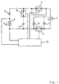
- FIG. 1 is a first embodiment of the invention shown which for any type of electromagnetic Actuators is suitable, such as Solenoid valves, relays or electric motors. Symbolic for these types of actuators is the Fig. 1, the electromagnetic actuator (1) as a relay coil shown.
- the actuator (1) is connected via a first switching means (2, 3) with the energy supply device (4, 5, 8, 9) connectable.
- the energy supply device (4, 5, 8, 9) has a battery (4) in this embodiment, a diode (5), one serving as second switching means Switch (8) and one serving as an energy store Capacitor (9).
- the battery (4) and the diode (5) serve as an energy output device.
- the first Switching means (2, 3) has a first switch (2) and a second switch (3).
- the switches (2, 3) symbolize suitable electrical or electronic Components with a switching function, such as. B. semiconductor switches, preferably field effect transistors. It can however also any other components with switching function can be used in the respective application the present requirements meet become.
- the switch (8) and the cathode of the diode (5) are connected to the switch (2).
- the capacitor (9) is connected in series with the switch (8).
- the battery (4) which has a nominal voltage (U 1 ), is connected in series with the diode (5).
- the battery (4) and the capacitor (9) are in turn connected to the switch (3).
- the diode (7) connects the actuator side Connection of the switch (3) with the circuit side Connection of the switch (2) in the direction of flow.
- the Diode (6) connects the circuit-side connection of the Switch (3) with the actuator-side connection of the Switch (2) in the direction of flow.
- the energy recovery arrangement (6, 7) serves to feed back one in the electromagnetic Actuator (1) stored energy supply in the capacitor (9), with the purpose of maintaining the of the Battery (4) set polarity the current direction in the circuit-side, from the switches (2, 3) to the capacitor (9) leading lines compared to the current direction when the switches (2, 3) are switched on is reversed.
- the switches (2, 3, 8) have a control connection, via the respective by means of a control signal Switch can be opened or closed.
- a control module (10) is provided which is connected via lines with the control inputs of the switches (2, 3, 8) connected is.
- the control module (10) is also for Power supply connected to the battery (4).
- the capacitor (9 ) By alternately switching the first switching means (2, 3) on the one hand and the second switching means (8) on the other hand, as will be explained in more detail below with the aid of a timing diagram, the capacitor (9 ) a charge or amount of energy is accumulated and given to the actuator (1) if necessary. As soon as the switches (2, 3) of the first switching means are closed as a result of control signals from the control module (10), a current flows from the battery (4) through the switch (2), the actuator, via the diode (5) acting in the direction of flow (1) and the switch (3). If no energy is stored in the capacitor (9), the control module (10) also actuates the switch (8) so that the capacitor (9) is reduced to the battery voltage (U 1 ) reduced by the diode forward voltage of the diode (5).
- FIG. 2 is a second embodiment of the invention shown, which is particularly for use of DC motors with a collector as an actuator is suitable, with the DC motor in both Direction of rotation can be operated.
- Switching means exist in this second embodiment from four switches (2, 3, 12, 13).
- the Switches (2, 3) are arranged in a manner analogous to that in FIG. 1.
- the switches (12, 13) are used for reversal the voltage polarity on that in this embodiment designed as a DC motor (11) actuator (1). Therefore, depending on the desired direction of rotation of the DC motor (11) either the switches (2, 3) or the switches (12, 13) are switched on.
- Energy recovery arrangement exhibits in the embodiment 2 two further diodes (14, 15) on.
- the four diodes (6, 7, 14, 15) of the energy recovery arrangement are like a bridge rectifier arranged such that regardless of the voltage polarity on the DC motor (11) one flowing out after opening the switches (2, 3, 12, 13) Amount of energy with that corresponding to the battery (4) Polarity is supplied to the capacitor (9).
- the one in this Embodiment of a main energy delivery device (4, 17) to be assigned battery (4) is another Switching means serving switch (17) upstream.
- the battery (4) is connected to the first switch (17) Switching means (2, 3, 12, 13) can be connected.
- the battery (16) is of a smaller design and therefore less expensive than the battery (4). For this reason, the battery (16) has a lower nominal voltage (U 2 ) than the battery (4).
- the switches (2, 3, 8, 12, 13, 17) are with an in 2 not for the sake of clarity shown control module in an analogous manner as in the Fig. 1 connected.
- the additional battery (16) serves as a redundant energy source in the event of a defect or failure of the battery (4).
- the electric motor (11) the nominal voltage of which is preferably matched to the nominal voltage (U 1 ) of the battery (4), is extracted exclusively from the battery (4). provided.
- the switches (8, 17) are constantly closed in this operating state.
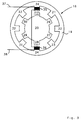
- FIG 3 is a cross section through a switched Reluctance motor (18) shown schematically.
- the Reluctance motor (18) has eight evenly over the circumference stator poles distributed on the inside of a stator (19) (21, 22, 23, 24, 31, 32, 33, 34) and six over the outer circumference of one arranged in the stator (19) Rotor (20) evenly distributed rotor poles (25, 26, 27, 28, 29, 30).
- the rotor (20) is mechanical connected to the output shaft of the reluctance motor (18).
- the opposite stator poles are each other assigned in pairs, in the following Pairs: (21) and (31), (22) and (32), (23) and (33), (24) and (34).
- the coil windings of two a pair of stator poles form an excitation winding.
- the coil windings of an excitation winding are connected to each other in such a way that when the Excitation winding one in both belonging to a pair Stator poles generated in the same direction magnetic flux becomes.
- the connection of two coil windings (35, 36) for an excitation winding is exemplary in FIG. 3 using the stator poles (24, 34).
- the stator pole (24) is provided with the coil (36)
- Stator pole (34) is provided with the coil (35).
- the connecting lines (37, 38) are provided.
- Simplification are in Fig. 3, the coils on the rest Stator poles not shown.
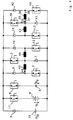
- 4 is a third embodiment of the invention shown, which for the with reference to FIG. 3rd explained switched reluctance motor (18) in particular is advantageous. 4 are of the reluctance motor (18) only the excitation windings of the stator poles (21, 22, 23, 24, 31, 32, 33, 34) and the connecting cables (37, 38). The excitation windings are here for simplification as individual coils or excitation windings (35/36, 43, 44, 45).
- Parts (4, 5, 8, 9, 16, 17) are in this embodiment the invention forming the first switching means Switches (2, 3, 12, 13, 39, 40) and the Energy-regenerative arrangement-forming diodes (6, 7, 14, 15, 41, 42) arranged in a particularly advantageous manner, so that the cost of components in proportion the complexity of the actuator used here (1, 18) is relatively small. In particular, are not for each excitation winding (35, 36, 43, 44, 45) two each Switch and two diodes required.
- two switches of the first switching means (2, 3, 12, 13, 39, 40) are actuated in pairs, thereby each of the excitation windings (35, 36 , 43, 44, 45).
- the switches (39, 40) for example, must be switched on to energize the excitation winding (35, 36). This then causes a current (I 35 ).
- the switches (2, 3) In order to effect a movement step of the reluctance motor (18) counterclockwise from the position shown in FIG. 3, the switches (2, 3) must be actuated, which causes a current flow (I 45 ) through the excitation winding (45).
- the switches (39, 40) are closed first after opening these switches, the flows in the amount of energy stored in the field winding (35, 36) via the diodes (41, 42) over the then closed Switch (8) in the capacitor (9).
- the desk As mentioned, (17) is open. After reaching one for one movement step of the reluctance motor (18) sufficient amount of energy in the capacitor (9) this amount of energy is transferred to the excitation winding, for example (45), for which the switches (2, 3, 8) would be close. After completing the movement step the switches (2, 3) are then opened, whereby the one stored in the field winding (45) The amount of energy then in turn via the diodes (6, 7) the condenser (9) flows off.
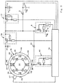
- FIG. 5 is a preferred variant of that in the Fig. 4 shown third embodiment of the invention with a switched reluctance motor (18) as Actuator shown, next to the control module (10) here also an advantageous circuit Execution of the switch (2, 3, 8, 12, 13, 17, 39, 40) specified components is specified.
- the simplicity for the sake of FIG. 5 is only the wiring the excitation winding, not shown in FIG. 5 (35, 36), as already shown in FIGS. 3 and 4, specified in detail.
- the excitation winding (35, 36) can via the connecting lines (37, 38), the with contacts (46) of the reluctance motor (18) are connected to be supplied with current.
- further connection contacts (46) are the further field windings (43, 44, 45) with further connecting lines connected (excitation windings and connecting cables are also not shown).
- the switches (8, 17, 39, 40) each consist of a field effect transistor with a series resistor at the gate connection and a Bridging resistance between the respective gate connection and the respective source connection.
- the bridging resistance serves a defined Ensure switching state of the field effect transistor if a high-resistance signal from the control module (10) is given to the gate series resistor.
- a position sensor (47) arranged, which is connected to the control module (10). Based the signal from the position sensor (47) can be the control module (10) recognize the angular position of the Rotor (20) is located and, as a result, a suitable one Excitation winding for the next movement step of the Determine the rotor (20).
- circuit arrangement corresponds to 5 of the representation according to FIG. 4.
- a suitable dimensioning of the capacitor (9) is about 1000 to 5000 ⁇ F.
- FIG. 6 shows a voltage-time diagram and two current-time diagrams when operating the third embodiment of the invention, as already explained with reference to FIGS. 4 and 5.
- the vertical dashed lines create a time reference between certain points in time (60, 61, 62, 63, 64, 65, 66, 67) in the individual diagrams.
- the diagrams show the course of the signals given there in the event of battery (4) failure, ie only the battery (16) with the battery (4) compared to the nominal voltage (U 1 ) is available to supply the circuit arrangement ) relatively low nominal voltage (U 2 ).
- the switch (17) is permanently open to avoid undesirable effects of the defective battery (4) on the rest of the circuit arrangement.
- the voltage (U 9 ) across the capacitor (9) is shown in the upper diagram.
- the current (I 35 ) through the field winding (35, 36) is shown in the middle diagram.
- the current (I 45 ) through the field winding (45) is shown in the lower diagram.
- the process described below begins at the time (60) at which the switches (8, 39, 40) are closed.
- the voltage (U 9 ) on the capacitor (9) rises abruptly to the voltage (U 2 ) of the battery (16).
- the current (I 35 ) gradually increases according to an exponential function.
- the switches (39, 40) are then opened while the switch (8) remains closed.
- the time for this is advantageously determined in such a way that the current increase in the current (I 35 ) is just before or already in the flattening branch of the exponential function. Switching off the switches (39, 40) reduces the current (I 35 ) according to an exponential function.
- the amount of energy delivered to the capacitor (9) via the diodes (41, 42) leads to an increase in the voltage there (U 9 ), which likewise runs according to an exponential function.
- the current (I 35 ) has essentially decreased to the value zero.
- the process described above is then repeated by switching the switches (39, 40) on again, the switch (8) now being opened in order to avoid a reduction in the already increased voltage (U 9 ) in the capacitor (9).
- the switches (39, 40) are then opened again and the switch (8) is closed at the same time. This causes a further increase in the voltage (U 9 ) across the capacitor (9).
- the amount of energy accumulated in the capacitor (9) is then fed to the reluctance motor (18) in order to thereby cause a movement step of the rotor (20).
- the excitation winding (45) is acted upon by the capacitor voltage (U 9 ) by simultaneously closing the switches (8, 2, 3) when the switch (17) is open.
- a current (I 45 ) builds up in the excitation winding (45), the capacitor (9) being discharged.
- the current (I 45 ) initially rises and decays after reaching a maximum.
- the voltage (U 9 ) decreases between the times (63, 54) in the manner of an exponential function.
- the aforementioned support by the battery (16) from the point in time (64) allows a movement of the rotor (20) initiated as a result of the initially relatively high capacitor voltage (U 9 ) to be continued until a movement step of the rotor (20) has ended, ie until in the present case the stator poles (21, 31) are aligned with the rotor poles (26, 29). Only an initial torque of the rotor (20) is thus generated by means of the capacitor voltage (U 9 ).
- An advantage here is that a relatively small and inexpensive capacitor with a relatively low capacitance can be used.
- Another advantage of a capacitor with low capacitance is that only relatively few actuation steps of the switches are required to achieve a sufficient voltage on the capacitor (9).
- Another advantage is that when the switch (8) is switched on, the capacitor voltage (U 9 ) can be kept at the value (U 2 ) and thus does not drop to the value zero.
- the switches (2, 3) are then opened simultaneously, which leads to a reduction in the current (I 45 ) and a capacitor voltage (U 9 ) which increases as a result of the energy compensation via the diodes (6, 7) .
- the switches (2, 3) and (8) are actuated alternately in an analogous manner as previously explained for the times (60, 61, 62, 63).
- Embodiment of the invention can by a test mode to test the additional battery (16), the diode (5) and the one used to collect the energy reserve Circuit parts (2, 3, 6, 7, 8, 9, 12, 13, 14, 15, 39, 40, 41, 42) can be advantageously expanded.
- the battery (16) as redundancy in the event of a defect the battery (4) is provided, the battery (16) in the normal case of a functional battery (4) not used, so without further action it cannot be guaranteed that the battery (16) in turn is functional when used should come.
- a safety-critical System e.g. B. a brake system for a Vehicle, it is for operational safety reasons but required a defect in the battery (16) recognize and display.
- the capacitor voltage (U 9 ) is preferably monitored by the control module (10).
Landscapes
- Engineering & Computer Science (AREA)
- Power Engineering (AREA)
- Business, Economics & Management (AREA)
- Emergency Management (AREA)
- Control Of Electric Motors In General (AREA)
- Stand-By Power Supply Arrangements (AREA)
- Valves And Accessory Devices For Braking Systems (AREA)
Abstract
Description
- Fig. 1
- ein elektrisches Schaltbild einer ersten Ausführungsform der Erfindung, welche für beliebige Arten von elektromagnetischen Stellgliedern geeignet ist, und
- Fig. 2
- eine zweite Ausführungsform der Erfindung, welche für Gleichstrommotoren mit Kollektor als Stellglieder besonders vorteilhaft ist, und
- Fig. 3
- einen Querschnitt durch einen geschalteten Reluktanzmotor in schematischer Darstellung und
- Fig. 4
- eine dritte Ausführungsform der Erfindung, welche für einen geschalteten Reluktanzmotor als Stellglied besonders vorteilhaft ist, und
- Fig. 5
- eine Variante der dritten Ausführungsform der Erfindung mit einem geschalteten Reluktanzmotor als Stellglied und
- Fig. 6
- Spannungs-/Zeitdiagramme beim erfindungsgemäßen Betrieb der Ausführungsform gemaß Fig. 4.
- In einer Zeitphase, in der der Reluktanzmotor (18) keine Stellbewegung ausführen muß, wird der Schalter (17) geöffnet.
- Die in dem Kondensator (9) gespeicherte Energiemenge wird derjenigen Erregerwicklung des Reluktanzmotors (18) durch Schließen der entsprechenden Schalter des ersten Schaltmittels (2, 3, 12, 13, 39, 40) zugeführt, deren Statorpole wenigstens annähernd mit den Rotorpolen fluchten. Hierbei führt der Rotor (20) dann im wesentlichen keine Bewegung aus, und die in dem Kondensator (9) gespeicherte Energiemenge wird in Wärme umgesetzt.
- Wenn die Kondensatorspannung (U9) auf den Spannungswert (U2) abgefallen ist, wird durch wechselweises Öffnen und Schließen der ersten (2, 3, 12, 13, 39, 40) und der zweiten (8) Schaltmittel stufenweise ein Energievorrat in dem Kondensator (9) gesammelt. Hierbei erhöht sich die Kondensatorspannung (U9), wie auch in der Fig. 6 dargestellt.
- Wenn die Kondensatorspannung (U9) nach einer vorgegebenen Zeitspanne wenigstens einen vorgegebenen Spannungswert, beispielsweise den Spannungswert (U1), erreicht hat, kann die Batterie (16) als funktionsfähig angesehen werden. Anderenfalls ist die Batterie (16) defekt, was z. B. mittels einer Warnlampe angezeigt werden kann.
- Sodann wird der Schalter (17) wieder geschlossen.
Claims (21)
- Schaltungsanordnung zum Betreiben eines elektromagnetischen Stellglieds (1, 11, 18), einem ersten Schaltmittel (2, 3, 12, 13, 39, 40), über das das Stellglied (1, 11, 18) mit einer elektrischen Energieversorgungseinrichtung (4, 5, 8, 9, 16, 17) verbindbar ist, und mit einer zwischen der Energieversorgungseinrichtung (4, 5, 8, 9, 16, 17) und dem Stellglied (1, 11, 18) angeordneten Energie-Rückspeisungsanordnung (6, 7, 14, 15, 41, 42), welche eine nach dem Öffnen des ersten Schaltmittels (2, 3, 12, 13, 39, 40) in dem Stellglied (1, 11, 18) gespeicherte Energiemenge in die Energieversorgungseinrichtung (4, 5, 8, 9, 16, 17) zurückspeist, wobei die Energieversorgungseinrichtung (4, 5, 8, 9, 16, 17) wenigstens eine Energieabgabeeinrichtung (4, 5, 16, 17) und wenigstens einen zur Energieabgabe und Energieaufnahme geeigneten Energiespeicher (9) sowie ein zweites Schaltmittel (8) aufweist, über das der Energiespeicher (9) mit der EnergieRückspeisungsanordnung (6, 7, 14, 15, 41, 42) verbindbar ist, dadurch gekennzeichnet, daß durch wechselweises Öffnen und Schließen der ersten (2, 3, 12, 13, 39, 40) und der zweiten (8) Schaltmittel stufenweise ein erwünschter Energievorrat in dem Energiespeicher (9) gesammelt wird.
- Anordnung nach Anspruch 1, dadurch gekennzeichnet, daß der in dem Energiespeicher (9) gesammelte Energievorrat bei Bedarf an das Stellglied (1, 11, 18) abgebbar ist.
- Anordnung und Verfahren nach einem der vorhergehenden Ansprüche, dadurch gekennzeichnet, daß das stufenweise Sammeln eines Energievorrats in dem Energiespeicher (9) vorgenommen wird, wenn das Stellglied (1, 11, 18) bei Verbindung mit der Energieabgabeeinrichtung (4, 5, 16, 17) eine Stellkraft erzeugt, die unterhalb eines erwünschten Wertes liegt.
- Anordnung und Verfahren nach einem der vorhergehenden Ansprüche, dadurch gekennzeichnet, daß für das stufenweise Sammeln des Energievorrats in dem Energiespeicher (9) das erste Schaltmittel (2, 3, 12, 13, 39, 40) derart betätigt wird, daß das Stellglied (1, 11, 18) im wesentlichen keine Stellbewegung ausführt.
- Anordnung und Verfahren nach einem der vorhergehenden Ansprüche, dadurch gekennzeichnet, daß die Energieabgabeeinrichtung (4, 5, 16, 17) eine Haupt-Energieabgabeeinrichtung (4, 17) und eine parallel dazu angeordnete Zusatz-Energieabgabeeinrichtung (5, 16) aufweist.
- Anordnung und Verfahren nach Anspruch 5, dadurch gekennzeichnet, daß das stufenweise Sammeln des Energievorrats in dem Energiespeicher (9) bei einer Betriebsstörung oder einem Ausfall der Haupt-Energieabgabeeinrichtung (4, 17) vorgenommen wird.
- Anordnung und Verfahren nach einem der Ansprüche 5 oder 6, dadurch gekennzeichnet, daß die Haupt-Energieabgabeeinrichtung (4, 17) und/oder die ZusatzEnergieabgabeeinrichtung (5, 16) ausschließlich zur Abgabe und nicht zur Aufnahme von elektrischer Energie geeignet ist.
- Anordnung und Verfahren nach einem der Ansprüche 5 bis 7, dadurch gekennzeichnet, daß die Haupt-Energieabgabeeinrichtung (4, 17) und/oder die Zusatz-Energieabgabeeinrichtung (5, 16) eine Energiequelle (4 bzw. 16), insbesondere eine wiederaufladbare Batterie, aufweist, zu der ein den Strom nur in Richtung zu der Energie-Ruckspeisungsanordnung durchlassendes Bauteil, insbesondere eine Diode (5), in Reihe geschaltet ist.
- Anordnung und Verfahren nach einem der Ansprüche 5 bis 8, dadurch gekennzeichnet, daß die Haupt-Energieabgabeeinrichtung (4, 17) und/oder die Zusatz-Energieabgabeeinrichtung (5, 16) eine Energiequelle (4 bzw. 16), insbesondere eine wiederaufladbare Batterie, aufweist, zu der ein weiteres Schaltmittel (17) in Reihe geschaltet ist.
- Anordnung und Verfahren nach einem der Ansprüche 5 bis 9, dadurch gekennzeichnet, daß die Nennspannung der Zusatz-Energieabgabeeinrichtung (5, 16) wesentlich geringer ist als die Nennspannung der Haupt-Energieabgabeeinrichtung (4, 17).
- Anordnung und Verfahren nach einem der vorhergehenden Ansprüche, dadurch gekennzeichnet, daß die Energie-Rückspeisungsanordnung (6, 7, 14, 15, 41, 42) das erste Schaltmittel (2, 3, 12, 13, 39, 40) überbrückt.
- Anordnung und Verfahren nach einem der vorhergehenden Ansprüche, dadurch gekennzeichnet, daß die Schaltmittel (2, 3, 8, 12, 13, 17, 39, 40) als Halbleiterschalter ausgebildet sind und von einem Steuermodul (10) aus steuerbar sind.
- Anordnung und Verfahren nach einem der vorhergehenden Ansprüche, dadurch gekennzeichnet, daß das Stellglied (1, 11, 18) ein Elektromotor (11, 18) ist.
- Anordnung und Verfahren nach Anspruch 13, dadurch gekennzeichnet, daß der Elektromotor (11) ein Gleichstrommotor mit einem Anker, einem Kommutator und zwei elektrischen Anschlüssen ist.
- Anordnung und Verfahren nach Anspruch 13, dadurch gekennzeichnet, daß der Elektromotor (18) eine Mehrzahl von Erregerwicklungen (35, 36, 43, 44, 45) aufweist, die über elektrische Anschlüsse mit elektrischer Energie beaufschlagbar sind.
- Anordnung und Verfahren nach Anspruch 13, dadurch gekennzeichnet, daß der Elektromotor (18) ein geschalteter Reluktanzmotor ist.
- Anordnung und Verfahren nach einem der Ansprüche 15 oder 16, dadurch gekennzeichnet, daß für das stufenweise Sammeln des Energievorrats in dem Energiespeicher (9) das erste Schaltmittel (2, 3, 12, 13, 39, 40) derart betätigt wird, daß diejenige Erregerwicklung (35, 36, 43, 44, 45) des Elektromotors (18) mit der Energieabgabeeinrichtung (4, 5, 16, 17) verbunden wird, deren Statorpole (21, 22, 23, 24, 31, 32, 33, 34) den Rotorpolen (25, 26, 27, 28, 29, 30) am nächsten stehen.
- Anordnung und Verfahren nach einem der Ansprüche 15 oder 16, dadurch gekennzeichnet, daß für das stufenweise Sammeln des Energievorrats in dem Energiespeicher (9) das erste Schaltmittel (2, 3, 12, 13, 39, 40) derart betätigt wird, daß mehrere oder alle Erregerwicklungen (35, 36, 43, 44, 45) des Elektromotors (18) gleichzeitig mit der Energieabgabeeinrichtung (4, 5, 16, 17) verbunden werden.
- Anordnung und Verfahren nach einem der vorhergehenden Ansprüche, dadurch gekennzeichnet, daß das Stellglied (1, 11, 18) ein Elektromagnet ist.
- Anordnung und Verfahren nach Anspruch 19, dadurch gekennzeichnet, daß der Elektromagnet in einem Magnetventil angeordnet ist.
- Verfahren zur Überprüfung einer Schaltungsanordnung nach einem der Ansprüche 9 bis 20, wobei die Haupt-Energieabgabeeinrichtung (4, 17) eine Energiequelle (4), insbesondere eine wiederaufladbare Batterie, aufweist, zu der ein weiteres Schaltmittel (17) in Reihe geschaltet ist, dadurch gekennzeichnet, daß bei fehlerfreiem Zustand der Energiequelle (4) nach Art eines Testzyklus das weitere Schaltmittel (17) vorübergehend geöffnet wird und währenddessen durch wechselweises Öffnen und Schließen der ersten (2, 3, 12, 13, 39, 40) und der zweiten (8) Schaltmittel stufenweise ein für eine Überprüfung der Schaltungsanordnung erwünschter Energievorrat in dem Energiespeicher (9) gesammelt wird.
Applications Claiming Priority (2)
| Application Number | Priority Date | Filing Date | Title |
|---|---|---|---|
| DE19931972A DE19931972A1 (de) | 1999-07-09 | 1999-07-09 | Schaltungsanordnung zum Betreiben eines elektromagnetischen Stellglieds |
| DE19931972 | 1999-07-09 |
Publications (2)
| Publication Number | Publication Date |
|---|---|
| EP1067668A2 true EP1067668A2 (de) | 2001-01-10 |
| EP1067668A3 EP1067668A3 (de) | 2002-05-08 |
Family
ID=7914165
Family Applications (1)
| Application Number | Title | Priority Date | Filing Date |
|---|---|---|---|
| EP00109136A Withdrawn EP1067668A3 (de) | 1999-07-09 | 2000-05-05 | Schaltungsanordnung zum Betreiben eines elektromagnetischen Stellglieds |
Country Status (4)
| Country | Link |
|---|---|
| US (1) | US6646851B1 (de) |
| EP (1) | EP1067668A3 (de) |
| JP (1) | JP2001086792A (de) |
| DE (1) | DE19931972A1 (de) |
Cited By (4)
| Publication number | Priority date | Publication date | Assignee | Title |
|---|---|---|---|---|
| EP1039625A3 (de) * | 1999-03-23 | 2002-05-22 | Switched Reluctance Drives Limited | Betrieb einer geschalteten Reluktanzmaschine mit dualer Versorgungsspannung |
| EP1209790A1 (de) * | 2000-11-23 | 2002-05-29 | Switched Reluctance Drives Limited | Mit zwei Spannungsversorgungen gespeister geschalteter Reluktanzantrieb und Verfahren für dessen Betrieb |
| CN103119666A (zh) * | 2010-09-21 | 2013-05-22 | Zf腓德烈斯哈芬股份公司 | 执行装置和用于驱控的方法 |
| EP4567842A1 (de) * | 2023-12-05 | 2025-06-11 | Murrelektronik GmbH | Schaltungsanordnung zum betätigen eines elektromagnetischen linearantriebs |
Families Citing this family (14)
| Publication number | Priority date | Publication date | Assignee | Title |
|---|---|---|---|---|
| US6791209B2 (en) * | 2002-01-02 | 2004-09-14 | Intel Corporation | Power and control for power supply fans |
| DE10258931A1 (de) * | 2002-12-16 | 2004-07-15 | Jungheinrich Aktiengesellschaft | Flurförderzeug mit elektrischer Bremse |
| CZ17567U1 (cs) * | 2005-11-08 | 2007-06-11 | Martin Professional A/S | Brzdný systém pro pohyb sestav svítidel |
| US20070188967A1 (en) * | 2006-02-10 | 2007-08-16 | Eaton Corporation | Solenoid driver circuit |
| US7586279B2 (en) * | 2006-11-09 | 2009-09-08 | Honeywell International Inc. | Actuator position switch |
| US7911758B2 (en) * | 2008-05-13 | 2011-03-22 | Automatic Switch Company | Low power solenoid control system and method |
| US20090309054A1 (en) * | 2008-06-11 | 2009-12-17 | Automatic Switch Company | System and method of operating a solenoid valve at minimum power levels |
| DE102009000721A1 (de) * | 2009-02-09 | 2010-08-12 | Zf Friedrichshafen Ag | Ansteuerschaltung für eine Getriebebremse |
| JP5421954B2 (ja) * | 2011-05-18 | 2014-02-19 | 三菱電機株式会社 | 蓄電装置 |
| US9218075B2 (en) | 2012-11-01 | 2015-12-22 | Immersion Corporation | Haptically-enabled system with braking |
| DE102013108932A1 (de) * | 2013-08-19 | 2015-02-19 | Bayerische Motoren Werke Aktiengesellschaft | Sicherheitsrelevantes System in einem Fahrzeug |
| DE102015105355B4 (de) * | 2015-04-09 | 2025-10-02 | Jungheinrich Aktiengesellschaft | Antriebseinheit für ein Flurförderzeug |
| US10832846B2 (en) | 2018-08-14 | 2020-11-10 | Automatic Switch Company | Low power solenoid with dropout detection and auto re-energization |
| US11393616B2 (en) * | 2020-09-24 | 2022-07-19 | Logitech Europe S.A. | Electromagnetic pulse driver |
Family Cites Families (17)
| Publication number | Priority date | Publication date | Assignee | Title |
|---|---|---|---|---|
| US4442395A (en) * | 1978-10-02 | 1984-04-10 | Ga Industries Inc. | Pump failure protection for liquid transmission pipelines |
| NL8801697A (nl) * | 1988-07-05 | 1990-02-01 | Laurentius Wilhelmus Jozef Hoo | Electro-motor. |
| JPH0360330A (ja) * | 1989-07-27 | 1991-03-15 | Isuzu Motors Ltd | 電源装置 |
| DE69013324T2 (de) * | 1989-08-28 | 1995-02-16 | Sekoh Giken Kk | Motor vom reluktanz-typ. |
| US5084662A (en) * | 1990-04-03 | 1992-01-28 | Sunstrand Corporation | Unipolar converter for variable reluctance machines |
| IT1251259B (it) * | 1991-12-23 | 1995-05-05 | Elasis Sistema Ricerca Fiat | Circuito di comando di carichi prevalentemente induttivi, in particolare elettroiniettori. |
| US5357395A (en) * | 1992-06-25 | 1994-10-18 | Schlumberger Technology Corporation | Undervoltage protection circuit, system and method of operating same |
| WO1994000909A1 (fr) * | 1992-06-29 | 1994-01-06 | Kabushikigaisya Sekogiken | Moteur a reluctance capable de fournir un freinage par recuperation et moteur a courant continu |
| JPH06113589A (ja) * | 1992-09-29 | 1994-04-22 | Japan Servo Co Ltd | モ−タ駆動回路 |
| GB9225090D0 (en) * | 1992-12-01 | 1993-01-20 | Univ Cardiff | Performance enhancement of single phase switched motor by d c link voltage |
| JP3123869B2 (ja) * | 1993-11-26 | 2001-01-15 | 日本輸送機株式会社 | 直流分巻電動機の制御装置 |
| FR2723126B1 (fr) * | 1994-07-27 | 1996-09-27 | Ymos France Sa | Ensemble constitue d'une serrure electrique de portiere ayant une fonction secours electrique et de ses moyens de commande et d'alimentation |
| US5637974A (en) * | 1995-04-21 | 1997-06-10 | Itt Automotive Electrical Systems, Inc. | Method and apparatus for hybrid direct-indirect control of a switched reluctance motor |
| US5703456A (en) * | 1995-05-26 | 1997-12-30 | Emerson Electric Co. | Power converter and control system for a motor using an inductive load and method of doing the same |
| GB9513662D0 (en) * | 1995-07-05 | 1995-09-06 | Univ Warwick | Switched reluctance electric machine system |
| US5907466A (en) * | 1995-09-23 | 1999-05-25 | Robert Bosch Gmbh | Device and process for activating at least two electromagnetic loads |
| GB9906716D0 (en) * | 1999-03-23 | 1999-05-19 | Switched Reluctance Drives Ltd | Operation of a switched reluctance machine from dual supply voltages |
-
1999
- 1999-07-09 DE DE19931972A patent/DE19931972A1/de not_active Withdrawn
-
2000
- 2000-05-05 EP EP00109136A patent/EP1067668A3/de not_active Withdrawn
- 2000-06-02 JP JP2000204348A patent/JP2001086792A/ja active Pending
- 2000-07-10 US US09/612,890 patent/US6646851B1/en not_active Expired - Fee Related
Cited By (5)
| Publication number | Priority date | Publication date | Assignee | Title |
|---|---|---|---|---|
| EP1039625A3 (de) * | 1999-03-23 | 2002-05-22 | Switched Reluctance Drives Limited | Betrieb einer geschalteten Reluktanzmaschine mit dualer Versorgungsspannung |
| EP1209790A1 (de) * | 2000-11-23 | 2002-05-29 | Switched Reluctance Drives Limited | Mit zwei Spannungsversorgungen gespeister geschalteter Reluktanzantrieb und Verfahren für dessen Betrieb |
| US6628105B1 (en) | 2000-11-23 | 2003-09-30 | Switched Reluctance Drives Ltd. | Operation of switched reluctance drive systems from dual voltage sources |
| CN103119666A (zh) * | 2010-09-21 | 2013-05-22 | Zf腓德烈斯哈芬股份公司 | 执行装置和用于驱控的方法 |
| EP4567842A1 (de) * | 2023-12-05 | 2025-06-11 | Murrelektronik GmbH | Schaltungsanordnung zum betätigen eines elektromagnetischen linearantriebs |
Also Published As
| Publication number | Publication date |
|---|---|
| DE19931972A1 (de) | 2001-01-11 |
| EP1067668A3 (de) | 2002-05-08 |
| US6646851B1 (en) | 2003-11-11 |
| JP2001086792A (ja) | 2001-03-30 |
Similar Documents
| Publication | Publication Date | Title |
|---|---|---|
| DE69219812T2 (de) | Steuerschaltung mit Energierückgewinnung für einen Reluktanzmotor | |
| EP1067668A2 (de) | Schaltungsanordnung zum Betreiben eines elektromagnetischen Stellglieds | |
| DE4421540B4 (de) | Startergerät für Fahrzeuge | |
| EP2548757B1 (de) | Antriebssystem und Verfahren zum Betrieb eines solchen Antriebssystems | |
| EP3592611B1 (de) | Nutzfahrzeug und verfahren zum betreiben eines nutzfahrzeuges | |
| EP2553255A2 (de) | Schaltvorrichtung, startvorrichtung und verfahren einer elektromagnetischen schaltvorrichtung | |
| WO2011042237A1 (de) | Verfahren zum betreiben eines antriebsaggregats sowie antriebsaggregat | |
| DE102020206478A1 (de) | Steuervorrichtung für einen Stromrichter, elektrisches Antriebssystem und Verfahren zum Einstellen eines sicheren Betriebszustandes | |
| EP3915127B1 (de) | Gleichstrom-schutzschaltgerät | |
| EP3142247B1 (de) | Schaltungsanordnung | |
| DE4223216A1 (de) | Sicherheitseinrichtung für Elektromotoren | |
| DE102021129144B4 (de) | Verfahren zum Betreiben einer elektrischen Schaltungsanordnung, elektrische Schaltung und Kraftfahrzeug | |
| EP3092706A1 (de) | Verfahren zum betreiben eines aktiven gleichrichters, schaltungsanordnung und computerprogramm | |
| WO2016128165A1 (de) | Verfahren zum betreiben eines an eine elektrische maschine angeschlossenen aktiven umrichters und mittel zu dessen implementierung | |
| DE102017204091A1 (de) | Schaltvorrichtung zum Schalten eines elektrischen Erregerstroms für eine elektrische Maschine mit einem Läufer | |
| EP3520196B1 (de) | Spannungsregler einer lichtmaschine | |
| DE102022131772B4 (de) | Ansteueranordnung und Verfahren zum Betreiben einer elektrischen Maschine | |
| DE102016203755A1 (de) | Motorstarter und Diagnoseverfahren | |
| DE102016106547A1 (de) | Schaltereinrichtung für einen elektromotor, steuereinrichtung, lenksystem | |
| DE102017200904A1 (de) | Leistungsansteuervorrichtung für eine elektrische Maschine und Verfahren zum Abtrennen einer elektrischen Maschine von einem elektrischen Energiespeicher | |
| DE102016202169A1 (de) | Betreiben einer Anordnung aus generatorisch betriebener elektrischer Maschine und aktivem Brückengleichrichter | |
| EP3075593B1 (de) | Verfahren zum entladen eines elektrischen energiespeichers eines kraftfahrzeugs | |
| DE102015202912B3 (de) | Verfahren und Vorrichtung zum Ansteuern eines aktiven Brückengleichrichters bei Aufhebung eines Phasenkurzschlusses | |
| DE102015105355B4 (de) | Antriebseinheit für ein Flurförderzeug | |
| EP4030574B1 (de) | Startersystem für eine brennkraftmaschine in einem fahrzeug |
Legal Events
| Date | Code | Title | Description |
|---|---|---|---|
| PUAI | Public reference made under article 153(3) epc to a published international application that has entered the european phase |
Free format text: ORIGINAL CODE: 0009012 |
|
| AK | Designated contracting states |
Kind code of ref document: A2 Designated state(s): AT BE CH CY DE DK ES FI FR GB GR IE IT LI LU MC NL PT SE |
|
| AX | Request for extension of the european patent |
Free format text: AL;LT;LV;MK;RO;SI |
|
| PUAL | Search report despatched |
Free format text: ORIGINAL CODE: 0009013 |
|
| AK | Designated contracting states |
Kind code of ref document: A3 Designated state(s): AT BE CH CY DE DK ES FI FR GB GR IE IT LI LU MC NL PT SE |
|
| AX | Request for extension of the european patent |
Free format text: AL;LT;LV;MK;RO;SI |
|
| RIC1 | Information provided on ipc code assigned before grant |
Free format text: 7H 02P 5/05 A, 7H 02J 9/06 B, 7H 02J 7/34 B |
|
| 17P | Request for examination filed |
Effective date: 20021108 |
|
| AKX | Designation fees paid |
Designated state(s): DE FR IT SE |
|
| RAP1 | Party data changed (applicant data changed or rights of an application transferred) |
Owner name: WABCO GMBH |
|
| 17Q | First examination report despatched |
Effective date: 20090507 |
|
| STAA | Information on the status of an ep patent application or granted ep patent |
Free format text: STATUS: THE APPLICATION HAS BEEN WITHDRAWN |
|
| 18W | Application withdrawn |
Effective date: 20090808 |