EP1067825A2 - Anordnung und Verfahren zur Steuerung des Beleuchtungsspectrums - Google Patents
Anordnung und Verfahren zur Steuerung des Beleuchtungsspectrums Download PDFInfo
- Publication number
- EP1067825A2 EP1067825A2 EP00830455A EP00830455A EP1067825A2 EP 1067825 A2 EP1067825 A2 EP 1067825A2 EP 00830455 A EP00830455 A EP 00830455A EP 00830455 A EP00830455 A EP 00830455A EP 1067825 A2 EP1067825 A2 EP 1067825A2
- Authority
- EP
- European Patent Office
- Prior art keywords
- spectrum
- sources
- light
- characteristic
- ambient
- Prior art date
- Legal status (The legal status is an assumption and is not a legal conclusion. Google has not performed a legal analysis and makes no representation as to the accuracy of the status listed.)
- Granted
Links
Images





Classifications
-
- H—ELECTRICITY
- H05—ELECTRIC TECHNIQUES NOT OTHERWISE PROVIDED FOR
- H05B—ELECTRIC HEATING; ELECTRIC LIGHT SOURCES NOT OTHERWISE PROVIDED FOR; CIRCUIT ARRANGEMENTS FOR ELECTRIC LIGHT SOURCES, IN GENERAL
- H05B41/00—Circuit arrangements or apparatus for igniting or operating discharge lamps
- H05B41/14—Circuit arrangements
- H05B41/36—Controlling
-
- H—ELECTRICITY
- H05—ELECTRIC TECHNIQUES NOT OTHERWISE PROVIDED FOR
- H05B—ELECTRIC HEATING; ELECTRIC LIGHT SOURCES NOT OTHERWISE PROVIDED FOR; CIRCUIT ARRANGEMENTS FOR ELECTRIC LIGHT SOURCES, IN GENERAL
- H05B41/00—Circuit arrangements or apparatus for igniting or operating discharge lamps
- H05B41/14—Circuit arrangements
- H05B41/36—Controlling
- H05B41/38—Controlling the intensity of light
- H05B41/39—Controlling the intensity of light continuously
- H05B41/392—Controlling the intensity of light continuously using semiconductor devices, e.g. thyristor
- H05B41/3921—Controlling the intensity of light continuously using semiconductor devices, e.g. thyristor with possibility of light intensity variations
- H05B41/3922—Controlling the intensity of light continuously using semiconductor devices, e.g. thyristor with possibility of light intensity variations and measurement of the incident light
Definitions
- the present invention relates to a device and a method for controlled lighting of various types of environment.
- the object of the present invention is to provide a device and a method which are able to achieve automatic control of the lighting conditions in terms of the light spectrum.
- the expressions "light” and “light spectrum” are not to be regarded as referring necessarily to only radiation in the visible range.
- the spectrum of interest for the present invention may also comprise the infrared and ultraviolet range.
- the expression “light sources” may also be understood as referring to sources which emit in this extensive range of electromagnetic radiation.
- the lighting device comprises:
- the method according to the invention envisages the steps of:
- the user is able to define given characteristics of the preconfigured spectrum for the light required in the environment, the color temperature of the light in the environment, the correlated color temperature, or the like.
- the predefined parameters may consist of desired chromatic coordinates or an indication of a point in the plane of the chromatic coordinates.
- the chromatic coordinates may be those of a standard system, for example the system XYZ CIE 1931, or also of another colorimetric system which may be chosen randomly.
- the system is able to maintain these characteristics of the predefined spectrum, within predetermined tolerances, also when there is a variation in the natural lighting and/or artificial lighting conditions.
- the value of the characteristics of the ambient spectrum is determined by the control system and then compared with the corresponding characteristics of the preconfigured spectrum.
- the feedback system regulates the conditions for supplying power to the light sources by modifying, for example, the power supplied to one or other or several of the light sources, so as to adjust the conditions of the ambient spectrum to the desired value, i.e. to the value of the corresponding characteristics of the preconfigured spectrum.
- the environmental lighting obtained overall consists of the sum of the sources outside the system and the sources of the system.
- the latter vary the emission conditions so that the resultant lighting has the desired characteristics in terms of chromaticity, color temperature, or the like.
- the feedback system performs a continuous controlling function over time, which is repeated at desired time intervals, having a duration chosen on the basis of the required speed of adaptation of the system to the variation in the lighting conditions.
- the characteristics of the predefined spectrum are not constant, but variable, for example, during the course of the day.
- the feedback means will adjust the emission conditions of the individual sources not only depending on the variation in the external lighting conditions, but also depending on the preset program on the basis of which the lighting conditions are to be varied over time.
- three or more photodetectors or sensors are envisaged, being sensitive in different bands of the spectrum and consisting, for example, of photodiodes with passband filters, or other selective devices for the light spectrum, which are centered on different portions of the light spectrum.
- These sensors capture the signals reflected back from a suitable white object illuminated by the entire ambient light, with stability characteristics over time, or the signals from the group of sources, and send them to a control system which receives at its input also the parameters of the predefined spectrum.
- the differences between the measured parameters and the predefined parameters are then minimized when the difference exceeds (in terms of absolute value) a threshold value.
- the system may also be used to correct automatically any deviations in the characteristics of the spectrum of the lighting produced by the light sources, due to aging of the lamps, a drop in the power supply voltage, or the like. In this sense, the system may also be used as a single lighting system in an environment which may also not receive any natural light.
- the algorithm may carry out a check as to the difference between each of the two chromaticity coordinates of the ambient light detected and the corresponding coordinates predefined by the user. On the basis of the difference thus determined, it is possible, using a processor, to check the power supply conditions of the individual sources in order to reduce and minimize the difference.
- a possible embodiment envisages at least three independent sources having different light-emission spectra, for example with an emission band centered on red, on green and on blue, respectively.
- the light sources may consist, for example, of halogen lamps with respective passband filters.
- fluorescent lamps with emissions centered on the desired bands, discharge lamps or in any case light sources with the desired emission spectrum.
- incandescent lamps of the halogen or equivalent type are combined with fluorescent lamps.
- a particularly simple, low-cost and efficient device is obtained by using, as photodetection means, a plurality of photodetectors associated with corresponding optical filters. Basically at least three sensors or photodetectors are used, but it is also possible to use a greater number of photodetectors with respective filters centered on corresponding wavelength bands.
- the feedback means may be realized by means of a suitable hardware circuit.
- the feedback system is implemented by means of an algorithm performed, with the aid of software, by an electronic processor which receives at its input the data relating to the ambient spectrum (typically the chromaticity coordinates) and the corresponding data of the predefined spectrum. At its output the processor provides the signals controlling the programmable power supply units of the individual sources.
- the device and the method according to the invention may have a plurality of uses, for example in the provision of lighting installations for domestic, industrial or professional use.
- a system of this type allows the user to define the desired lighting characteristics and maintain them in the event of a variation in the external conditions.
- a particularly interesting use of the system is in the museum and exhibition sector where the optimum lighting conditions - not only in terms of intensity but also and in particular as regards the color temperature of the light used - may be chosen and maintained using said system.
- the functions x (( ⁇ ), y ( ⁇ ) and z ( ⁇ ) are color equality functions and their progression in the standard colorimetric system XYZ CIE 1931 is shown in Fig. 1.
- a given color is represented on an x-y diagram on which the abovementioned chromaticity coordinates are shown.
- the x-y diagram is shown in Fig. 2.
- a few properties are useful in the description of the system according to the present invention.
- the sum of these colors is represented by a point S3 which is located on the straight line which joins together the points S1 and S2.
- Fig. 3 shows how the position of the color S3 obtained from the sum of the colors S1 and S2 is determined.
- the point S3 is positioned on the straight line which passes through the points S1 and S2 and -has chromatic coordinates x3, y3 defined by:
- the abovementioned principles may be used in order to obtain a controlled-spectrum lighting system, in which the emission spectrum of the artificial light sources is controlled depending, for example, on the natural lighting, so as to obtain a color temperature of the lighting which is more or less constant and equal, within predefinable tolerance values, to a given value.
- the concept is schematically illustrated in Fig. 4: the x-y chromaticity diagram shows a first point SA which represents the color of the ambient light.
- SS indicates the point in the x-y diagram representing the light emitted by the artificial lighting system.
- ST represents the chromaticity point which is to be obtained with the system.
- the point ST is obtained as the sum of the two points representing the natural light source (SA) and the artificial light source (SS) and is therefore located on the line joining together the two points SA, SS.
- the device according to the invention is schematically shown, in the form of a block diagram, in Fig. 5A.
- the system has a first block 1 comprising a set of three sources R2, G2, B2 which emit red light, green light and blue light, respectively.
- the sources R2, G2 and B2 may be of a varied nature, for example halogen lamps or fluorescent lamps. Examples of lamps will be described below and characterized by means of the associated emission diagrams.
- the sources R2, G2 and B2 emit a light which is added to the ambient light which may be produced by the natural light and/or by other artificial light sources.
- the resultant light is captured by a colorimeter, generally indicated by the block 2, comprising three photodetectors F1, F2, F3 in front of which three optical filters R1, G1, B1 are arranged.
- the outputs of the three photodetectors F1, F2, F3 are sent to a converter block which will be described in greater detail below and from which the abovementioned tristimulus values X, Y, Z for the light captured by the photodetection system, comprising the filters R1, G1, B1 and the photodetectors F1, F2, F3, are obtained.
- a control system represented by the block 3 determines the values of the x-y coordinates in the chromaticity diagram. These values are indicated by xS and yS in the block diagram according to Fig. 5.
- the calculation of the chromaticity coordinates is performed, for example, with the aid of software, via a processor.
- the processor also receives at its input, via a user interface 5, a pair of values xi, yi representing the chromaticity coordinates of the point in the x-y chromaticity diagram to be obtained by means of the lighting device.
- the coordinates xi, yi indicate the position in which the point indicated in the diagram of Fig. 4 by ST must be located. If the coordinates xS and yS differ from the coordinates xi, yi, this means that the overall lighting (provided by the sum of the ambient light and the light generated by the sources R2, G2, B2) does not correspond to the desired color.
- control unit modifies the power supply conditions of the sources R2, G2, B2 so as to correct the lighting conditions and bring the chromaticity coordinates xS and yS towards the set value xi, yi. This is obtained by means of the control block 7 which modifies the power supply conditions of the sources R2, G2, B2.
- the feedback algorithm may be configured in a varying manner. Generally, it is possible to use any algorithm which is able to generate a control parameter which, depending on the chromaticity coordinates detected, corrects the chromaticity coordinates of the source formed overall by the three sources R2, G2, B2 so as to obtain the predefined chromaticity coordinates.
- Fig. 6 shows, in the form of a flow diagram, a particularly simple algorithm for obtaining this function.
- the algorithm On the basis of the set values xi, yi and a tolerance value (t), representing the maximum permissible error between the set chromaticity coordinates and the measured coordinates, the algorithm performs the following steps:
- a check is performed as to whether the value of xS is greater than the value of xi. If it is (and if the power with which the source R2 is supplied is not equal to the maximum value), the value of the power supply of the red light source R2 - and therefore the luminous flux provided by this source - is incremented by a predefined quantity ( ⁇ R2). On the other hand, if the value of the power supply of the red light source R2 is already at its maximum value, the power supply of the blue light source B2 - and therefore the luminous flux generated by this source - is reduced by a predefined quantity ( ⁇ B2).
- the power supply of the green lamp G2 is reduced if yS is greater than or equal to yi; the power supply of the green light source G2 is increased if yS is less than yi.
- the feedback algorithm is performed at time intervals determined so that the emission characteristics of the sources R2, B2, G2 are constantly adapted so as to keep the chromaticity coordinates of the overall light in the region of the set value, with the tolerance t.
- the outputs of the three photodetectors F1, F2, F3 will correspond to tristimulus values in a system which is different from the standard system XYZ (and generically indicated by UVW in Fig. 5).
- the matrix which converts the tristimulus values in the generic system UVW to the XYZ system By means of suitable calibration of the photodetectors it is possible to determine the matrix which converts the tristimulus values in the generic system UVW to the XYZ system.
- the conversion block indicated by the numeral 8 in Fig. 5, performs the conversion from the UVW system to the XYZ system by means of the abovementioned matrix. Obviously the coefficients of the matrix change depending on the filter/photodetector system used.
- the block 3 may also be programmed so as to perform the calculation of the correlated color temperature (Tc) of the light obtained, for example by implementing, using software, one of the methods for determining the correlated color temperature, such as the Robertson method.
- Tc correlated color temperature
- both the luminous flux of said sources and the chromatic characteristics of the light emitted are varied.
- the system takes this into account by means of the feedback algorithm.
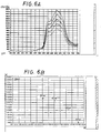
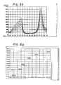
- the effect of variation of the chromaticity coordinates of the light emitted by the individual sources as a function of the power used is illustrated by the diagrams of Figs. 6-12, where Figs. 6 to 8 refer to halogen lamps with a dichroic reflector and passband filter, while Figs. 9 to 12 refer to fluorescent lamps.
- Fig. 6A shows the emission spectrum of a halogen lamp (model Osram Decostar Titan 46870FL made by OSRAM, Germany) equipped with a passband filter centered on red.
- the five graph curves refer to five different power consumption levels and, more particularly, to the power levels 28, 34, 40, 45 and 50 W (50 W being the rated power of the lamp).
- Fig. 6B shows the corresponding five points in the x-y chromaticity diagram of the standard system XYZ CIE 1931. It is obvious that, by varying the power supply of the lamp, the position of its chromaticity coordinates and essentially the color temperature of the emitted light change.
- Figs. 9A and 9B show the emission spectrum and the x-y chromaticity diagram of a red, tubular, fluorescent lamp, model Osram L58W/60, with a rated power of 60 W.
- the graph and the points in the chromaticity diagram are obtained for power levels of 6, 11, 17, 23, 29, 35, 40, 46, 52 and 58 W.
- Figs. 10A and 10B show the emission spectrum and the chromaticity diagram for a green, tubular, fluorescent lamp, model Osram L58W/66, for variable power supply levels of 17, 23, 29, 35, 40, 46, 52 and 58 W.
- Figs. 11 A and 11B show the emission spectrum and the chromaticity diagram for a blue, tubular, fluorescent lamp, model Osram L58W/66, for power levels of 23, 29, 35, 40, 46, 52 and 58 W.
- Figs. 12A, 12B and 12C show the progression of the luminous flux (% along the ordinate) as a function of the power used (W along the abscissa).
Landscapes
- Circuit Arrangement For Electric Light Sources In General (AREA)
Applications Claiming Priority (2)
| Application Number | Priority Date | Filing Date | Title |
|---|---|---|---|
| ITFI990158 | 1999-07-08 | ||
| IT1999FI000158A IT1308289B1 (it) | 1999-07-08 | 1999-07-08 | Dispositivo e metodo di illuminazione a spettro controllato |
Publications (3)
| Publication Number | Publication Date |
|---|---|
| EP1067825A2 true EP1067825A2 (de) | 2001-01-10 |
| EP1067825A3 EP1067825A3 (de) | 2002-06-12 |
| EP1067825B1 EP1067825B1 (de) | 2004-12-15 |
Family
ID=11353037
Family Applications (1)
| Application Number | Title | Priority Date | Filing Date |
|---|---|---|---|
| EP00830455A Expired - Lifetime EP1067825B1 (de) | 1999-07-08 | 2000-06-28 | Anordnung und Verfahren zur Steuerung des Beleuchtungsspectrums |
Country Status (5)
| Country | Link |
|---|---|
| EP (1) | EP1067825B1 (de) |
| AT (1) | ATE285165T1 (de) |
| DE (1) | DE60016674T2 (de) |
| ES (1) | ES2232410T3 (de) |
| IT (1) | IT1308289B1 (de) |
Cited By (19)
| Publication number | Priority date | Publication date | Assignee | Title |
|---|---|---|---|---|
| WO2002082863A1 (en) * | 2001-04-06 | 2002-10-17 | Koninklijke Philips Electronics N.V. | Method and system for controlling a light source |
| WO2003058184A1 (en) * | 2002-01-11 | 2003-07-17 | Koninklijke Philips Electronics N.V. | Method of determining tristimulus values for rgb led illuminants |
| EP1374643A1 (de) * | 2001-03-29 | 2004-01-02 | Koninklijke Philips Electronics N.V. | Anordnung für eine rgb led-leuchte |
| WO2005029019A1 (en) * | 2003-09-19 | 2005-03-31 | Koninklijke Philips Electronics, N.V. | Silicon-on-insulator photodiode optical monitoring system for color temperature control in solid state light systems |
| WO2007042984A1 (en) * | 2005-10-13 | 2007-04-19 | Koninklijke Philips Electronics N.V. | Method and system for variable color lighting |
| FR2915797A1 (fr) * | 2007-05-04 | 2008-11-07 | Thales Sa | Dispositif et procede de calibration d'une source lumineuse. |
| EP1393029B1 (de) * | 2001-05-08 | 2008-12-17 | Koninklijke Philips Electronics N.V. | System zum messen von chromatizitätskoordinaten |
| WO2009044330A1 (en) * | 2007-10-02 | 2009-04-09 | Koninklijke Philips Electronics N.V. | Lighting system, and method and computer program for controlling the lighting system |
| RU2419958C2 (ru) * | 2006-02-28 | 2011-05-27 | Бсх Бош Унд Сименс Хаусгерете Гмбх | Способ регулирования линейного привода или линейного компрессора, а также регулируемый линейный привод или линейный компрессор |
| RU2423024C2 (ru) * | 2006-02-10 | 2011-06-27 | Конинклейке Филипс Электроникс Н.В. | Контроль за устройством освещения |
| US10928842B2 (en) | 2012-08-28 | 2021-02-23 | Delos Living Llc | Systems and methods for enhancing wellness associated with habitable environments |
| US10952297B2 (en) | 2009-10-08 | 2021-03-16 | Delos Living Llc | LED lighting system and method therefor |
| CN112601316A (zh) * | 2020-12-30 | 2021-04-02 | 广东光阳电器有限公司 | 一种全光谱台灯照明方法及台灯 |
| US11338107B2 (en) | 2016-08-24 | 2022-05-24 | Delos Living Llc | Systems, methods and articles for enhancing wellness associated with habitable environments |
| US11649977B2 (en) | 2018-09-14 | 2023-05-16 | Delos Living Llc | Systems and methods for air remediation |
| US11668481B2 (en) | 2017-08-30 | 2023-06-06 | Delos Living Llc | Systems, methods and articles for assessing and/or improving health and well-being |
| US11763401B2 (en) | 2014-02-28 | 2023-09-19 | Delos Living Llc | Systems, methods and articles for enhancing wellness associated with habitable environments |
| US11844163B2 (en) | 2019-02-26 | 2023-12-12 | Delos Living Llc | Method and apparatus for lighting in an office environment |
| US11898898B2 (en) | 2019-03-25 | 2024-02-13 | Delos Living Llc | Systems and methods for acoustic monitoring |
Families Citing this family (5)
| Publication number | Priority date | Publication date | Assignee | Title |
|---|---|---|---|---|
| TW200925491A (en) | 2007-11-06 | 2009-06-16 | Koninkl Philips Electronics Nv | Light control system and method for automatically rendering a lighting atmosphere |
| CN101849434B (zh) | 2007-11-06 | 2013-11-20 | 皇家飞利浦电子股份有限公司 | 用于自动再现照明场景的光控制系统和方法 |
| EP3245631A4 (de) | 2015-01-13 | 2018-06-27 | Delos Living, LLC | Systeme, verfahren und artikel zur überwachung und steigerung des menschlichen wohlbefindens |
| CN105182809A (zh) * | 2015-07-22 | 2015-12-23 | 小米科技有限责任公司 | 调节智能窗帘透光度的方法、智能窗帘及装置 |
| CN105615599A (zh) * | 2015-12-29 | 2016-06-01 | 深圳市智汇十方科技有限公司 | 一种智能窗帘唤醒用户的方法及智能窗帘 |
Family Cites Families (5)
| Publication number | Priority date | Publication date | Assignee | Title |
|---|---|---|---|---|
| US2759392A (en) * | 1949-04-23 | 1956-08-21 | Gen Aniline & Film Corp | Color temperature meter and color analyzer |
| JPH0676961A (ja) * | 1992-08-26 | 1994-03-18 | Matsushita Electric Works Ltd | 可変色照明装置 |
| US5521708A (en) * | 1992-11-25 | 1996-05-28 | Canon Information & Systems, Inc. | Correlated color temperature detector |
| JPH0765963A (ja) * | 1993-08-25 | 1995-03-10 | Shimizu Corp | 自然光再現システム |
| US5569983A (en) * | 1994-03-22 | 1996-10-29 | Tailored Lighting Inc. | Electronic apparatus for producing variable spectral output |
-
1999
- 1999-07-08 IT IT1999FI000158A patent/IT1308289B1/it active
-
2000
- 2000-06-28 DE DE60016674T patent/DE60016674T2/de not_active Expired - Fee Related
- 2000-06-28 ES ES00830455T patent/ES2232410T3/es not_active Expired - Lifetime
- 2000-06-28 EP EP00830455A patent/EP1067825B1/de not_active Expired - Lifetime
- 2000-06-28 AT AT00830455T patent/ATE285165T1/de not_active IP Right Cessation
Cited By (26)
| Publication number | Priority date | Publication date | Assignee | Title |
|---|---|---|---|---|
| EP1374643A1 (de) * | 2001-03-29 | 2004-01-02 | Koninklijke Philips Electronics N.V. | Anordnung für eine rgb led-leuchte |
| US6576881B2 (en) | 2001-04-06 | 2003-06-10 | Koninklijke Philips Electronics N.V. | Method and system for controlling a light source |
| WO2002082863A1 (en) * | 2001-04-06 | 2002-10-17 | Koninklijke Philips Electronics N.V. | Method and system for controlling a light source |
| EP1393029B1 (de) * | 2001-05-08 | 2008-12-17 | Koninklijke Philips Electronics N.V. | System zum messen von chromatizitätskoordinaten |
| WO2003058184A1 (en) * | 2002-01-11 | 2003-07-17 | Koninklijke Philips Electronics N.V. | Method of determining tristimulus values for rgb led illuminants |
| WO2005029019A1 (en) * | 2003-09-19 | 2005-03-31 | Koninklijke Philips Electronics, N.V. | Silicon-on-insulator photodiode optical monitoring system for color temperature control in solid state light systems |
| US7990083B2 (en) | 2005-10-13 | 2011-08-02 | Koninklijke Philips Electronics N.V. | Method and system for variable color lighting |
| WO2007042984A1 (en) * | 2005-10-13 | 2007-04-19 | Koninklijke Philips Electronics N.V. | Method and system for variable color lighting |
| JP2009512153A (ja) * | 2005-10-13 | 2009-03-19 | コーニンクレッカ フィリップス エレクトロニクス エヌ ヴィ | 可変光照明のための方法及び装置 |
| CN101283628B (zh) * | 2005-10-13 | 2012-05-30 | 皇家飞利浦电子股份有限公司 | 用于可变色照明的方法和系统 |
| RU2423024C2 (ru) * | 2006-02-10 | 2011-06-27 | Конинклейке Филипс Электроникс Н.В. | Контроль за устройством освещения |
| RU2419958C2 (ru) * | 2006-02-28 | 2011-05-27 | Бсх Бош Унд Сименс Хаусгерете Гмбх | Способ регулирования линейного привода или линейного компрессора, а также регулируемый линейный привод или линейный компрессор |
| FR2915797A1 (fr) * | 2007-05-04 | 2008-11-07 | Thales Sa | Dispositif et procede de calibration d'une source lumineuse. |
| WO2009044330A1 (en) * | 2007-10-02 | 2009-04-09 | Koninklijke Philips Electronics N.V. | Lighting system, and method and computer program for controlling the lighting system |
| US10952297B2 (en) | 2009-10-08 | 2021-03-16 | Delos Living Llc | LED lighting system and method therefor |
| US11109466B2 (en) | 2009-10-08 | 2021-08-31 | Delos Living Llc | LED lighting system |
| US10928842B2 (en) | 2012-08-28 | 2021-02-23 | Delos Living Llc | Systems and methods for enhancing wellness associated with habitable environments |
| US11587673B2 (en) | 2012-08-28 | 2023-02-21 | Delos Living Llc | Systems, methods and articles for enhancing wellness associated with habitable environments |
| US11763401B2 (en) | 2014-02-28 | 2023-09-19 | Delos Living Llc | Systems, methods and articles for enhancing wellness associated with habitable environments |
| US11338107B2 (en) | 2016-08-24 | 2022-05-24 | Delos Living Llc | Systems, methods and articles for enhancing wellness associated with habitable environments |
| US11668481B2 (en) | 2017-08-30 | 2023-06-06 | Delos Living Llc | Systems, methods and articles for assessing and/or improving health and well-being |
| US11649977B2 (en) | 2018-09-14 | 2023-05-16 | Delos Living Llc | Systems and methods for air remediation |
| US11844163B2 (en) | 2019-02-26 | 2023-12-12 | Delos Living Llc | Method and apparatus for lighting in an office environment |
| US11898898B2 (en) | 2019-03-25 | 2024-02-13 | Delos Living Llc | Systems and methods for acoustic monitoring |
| CN112601316A (zh) * | 2020-12-30 | 2021-04-02 | 广东光阳电器有限公司 | 一种全光谱台灯照明方法及台灯 |
| CN112601316B (zh) * | 2020-12-30 | 2023-07-21 | 广东光阳电器有限公司 | 一种全光谱台灯照明方法及台灯 |
Also Published As
| Publication number | Publication date |
|---|---|
| ITFI990158A0 (it) | 1999-07-08 |
| IT1308289B1 (it) | 2001-12-10 |
| DE60016674D1 (de) | 2005-01-20 |
| EP1067825B1 (de) | 2004-12-15 |
| EP1067825A3 (de) | 2002-06-12 |
| ES2232410T3 (es) | 2005-06-01 |
| ATE285165T1 (de) | 2005-01-15 |
| ITFI990158A1 (it) | 2001-01-08 |
| DE60016674T2 (de) | 2006-03-16 |
Similar Documents
| Publication | Publication Date | Title |
|---|---|---|
| EP1067825B1 (de) | Anordnung und Verfahren zur Steuerung des Beleuchtungsspectrums | |
| US8009278B2 (en) | Customizable spectral profiles for filtering | |
| RU2434368C2 (ru) | Система и способ для управления светильником сид | |
| CN100531503C (zh) | 对于基于发光二极管的发光设备的彩色控制 | |
| CA2708980C (en) | Method and apparatus for digital control of a lighting device | |
| US7026769B2 (en) | Luminary control system adapted for reproducing the color of a known light source | |
| EP1346609B1 (de) | Led-leuchtsystem | |
| US9980327B2 (en) | Device and method for generating light of a predetermined spectrum with a plurality of differently colored light sources | |
| US8981672B2 (en) | Color control of dynamic lighting | |
| US10959305B2 (en) | Controlling a lighting device having at least two electric light sources | |
| EP1955577A1 (de) | Led-beleuchtungssystem und steuerverfahren | |
| CN103906325B (zh) | 照明控制方法和系统 | |
| Goudjil et al. | An interior-points algorithm for color and CCT control of multichannel LED lighting system using a Smart 18-Channel Spectral Sensor | |
| US10458841B2 (en) | Method for processing light sensor signals and light sensor system | |
| KR101080698B1 (ko) | 조명 장치 및 조명 장치의 제어 방법 | |
| EP2091301A1 (de) | Lichtmesssystem mit LEDs | |
| MXPA06009246A (es) | Lamparas. | |
| AU2006246531A1 (en) | Lamp | |
| Campus et al. | Development and Prototyping of a Solid State Lighting Product for Architectural and Accent Applications |
Legal Events
| Date | Code | Title | Description |
|---|---|---|---|
| PUAI | Public reference made under article 153(3) epc to a published international application that has entered the european phase |
Free format text: ORIGINAL CODE: 0009012 |
|
| AK | Designated contracting states |
Kind code of ref document: A2 Designated state(s): AT BE CH CY DE DK ES FI FR GB GR IE IT LI LU MC NL PT SE |
|
| AX | Request for extension of the european patent |
Free format text: AL;LT;LV;MK;RO;SI |
|
| PUAL | Search report despatched |
Free format text: ORIGINAL CODE: 0009013 |
|
| AK | Designated contracting states |
Kind code of ref document: A3 Designated state(s): AT BE CH CY DE DK ES FI FR GB GR IE IT LI LU MC NL PT SE |
|
| AX | Request for extension of the european patent |
Free format text: AL;LT;LV;MK;RO;SI |
|
| 17P | Request for examination filed |
Effective date: 20020809 |
|
| 17Q | First examination report despatched |
Effective date: 20021001 |
|
| AKX | Designation fees paid |
Designated state(s): AT BE CH CY DE DK ES FI FR GB GR IE IT LI LU MC NL PT SE |
|
| GRAP | Despatch of communication of intention to grant a patent |
Free format text: ORIGINAL CODE: EPIDOSNIGR1 |
|
| GRAS | Grant fee paid |
Free format text: ORIGINAL CODE: EPIDOSNIGR3 |
|
| GRAA | (expected) grant |
Free format text: ORIGINAL CODE: 0009210 |
|
| AK | Designated contracting states |
Kind code of ref document: B1 Designated state(s): AT BE CH CY DE DK ES FI FR GB GR IE IT LI LU MC NL PT SE |
|
| PG25 | Lapsed in a contracting state [announced via postgrant information from national office to epo] |
Ref country code: IT Free format text: LAPSE BECAUSE OF FAILURE TO SUBMIT A TRANSLATION OF THE DESCRIPTION OR TO PAY THE FEE WITHIN THE PRESCRIBED TIME-LIMIT;WARNING: LAPSES OF ITALIAN PATENTS WITH EFFECTIVE DATE BEFORE 2007 MAY HAVE OCCURRED AT ANY TIME BEFORE 2007. THE CORRECT EFFECTIVE DATE MAY BE DIFFERENT FROM THE ONE RECORDED. Effective date: 20041215 Ref country code: FI Free format text: LAPSE BECAUSE OF FAILURE TO SUBMIT A TRANSLATION OF THE DESCRIPTION OR TO PAY THE FEE WITHIN THE PRESCRIBED TIME-LIMIT Effective date: 20041215 Ref country code: CH Free format text: LAPSE BECAUSE OF FAILURE TO SUBMIT A TRANSLATION OF THE DESCRIPTION OR TO PAY THE FEE WITHIN THE PRESCRIBED TIME-LIMIT Effective date: 20041215 Ref country code: LI Free format text: LAPSE BECAUSE OF FAILURE TO SUBMIT A TRANSLATION OF THE DESCRIPTION OR TO PAY THE FEE WITHIN THE PRESCRIBED TIME-LIMIT Effective date: 20041215 |
|
| REG | Reference to a national code |
Ref country code: GB Ref legal event code: FG4D Ref country code: CH Ref legal event code: EP |
|
| REG | Reference to a national code |
Ref country code: IE Ref legal event code: FG4D |
|
| REF | Corresponds to: |
Ref document number: 60016674 Country of ref document: DE Date of ref document: 20050120 Kind code of ref document: P |
|
| PG25 | Lapsed in a contracting state [announced via postgrant information from national office to epo] |
Ref country code: SE Free format text: LAPSE BECAUSE OF FAILURE TO SUBMIT A TRANSLATION OF THE DESCRIPTION OR TO PAY THE FEE WITHIN THE PRESCRIBED TIME-LIMIT Effective date: 20050315 Ref country code: GR Free format text: LAPSE BECAUSE OF FAILURE TO SUBMIT A TRANSLATION OF THE DESCRIPTION OR TO PAY THE FEE WITHIN THE PRESCRIBED TIME-LIMIT Effective date: 20050315 Ref country code: DK Free format text: LAPSE BECAUSE OF FAILURE TO SUBMIT A TRANSLATION OF THE DESCRIPTION OR TO PAY THE FEE WITHIN THE PRESCRIBED TIME-LIMIT Effective date: 20050315 |
|
| REG | Reference to a national code |
Ref country code: ES Ref legal event code: FG2A Ref document number: 2232410 Country of ref document: ES Kind code of ref document: T3 |
|
| PG25 | Lapsed in a contracting state [announced via postgrant information from national office to epo] |
Ref country code: LU Free format text: LAPSE BECAUSE OF NON-PAYMENT OF DUE FEES Effective date: 20050628 Ref country code: CY Free format text: LAPSE BECAUSE OF FAILURE TO SUBMIT A TRANSLATION OF THE DESCRIPTION OR TO PAY THE FEE WITHIN THE PRESCRIBED TIME-LIMIT Effective date: 20050628 Ref country code: IE Free format text: LAPSE BECAUSE OF NON-PAYMENT OF DUE FEES Effective date: 20050628 |
|
| PG25 | Lapsed in a contracting state [announced via postgrant information from national office to epo] |
Ref country code: MC Free format text: LAPSE BECAUSE OF NON-PAYMENT OF DUE FEES Effective date: 20050630 |
|
| REG | Reference to a national code |
Ref country code: CH Ref legal event code: PL |
|
| PLBE | No opposition filed within time limit |
Free format text: ORIGINAL CODE: 0009261 |
|
| STAA | Information on the status of an ep patent application or granted ep patent |
Free format text: STATUS: NO OPPOSITION FILED WITHIN TIME LIMIT |
|
| ET | Fr: translation filed | ||
| 26N | No opposition filed |
Effective date: 20050916 |
|
| REG | Reference to a national code |
Ref country code: IE Ref legal event code: MM4A |
|
| PGFP | Annual fee paid to national office [announced via postgrant information from national office to epo] |
Ref country code: ES Payment date: 20070611 Year of fee payment: 8 |
|
| PGFP | Annual fee paid to national office [announced via postgrant information from national office to epo] |
Ref country code: BE Payment date: 20070612 Year of fee payment: 8 |
|
| PGFP | Annual fee paid to national office [announced via postgrant information from national office to epo] |
Ref country code: AT Payment date: 20070628 Year of fee payment: 8 |
|
| PGFP | Annual fee paid to national office [announced via postgrant information from national office to epo] |
Ref country code: NL Payment date: 20070629 Year of fee payment: 8 |
|
| PGFP | Annual fee paid to national office [announced via postgrant information from national office to epo] |
Ref country code: DE Payment date: 20070824 Year of fee payment: 8 |
|
| PGFP | Annual fee paid to national office [announced via postgrant information from national office to epo] |
Ref country code: GB Payment date: 20070627 Year of fee payment: 8 |
|
| PG25 | Lapsed in a contracting state [announced via postgrant information from national office to epo] |
Ref country code: PT Free format text: LAPSE BECAUSE OF NON-PAYMENT OF DUE FEES Effective date: 20050515 |
|
| PGFP | Annual fee paid to national office [announced via postgrant information from national office to epo] |
Ref country code: FR Payment date: 20070531 Year of fee payment: 8 |
|
| BERE | Be: lapsed |
Owner name: *TARGETTI SANKEY S.P.A. Effective date: 20080630 |
|
| GBPC | Gb: european patent ceased through non-payment of renewal fee |
Effective date: 20080628 |
|
| NLV4 | Nl: lapsed or anulled due to non-payment of the annual fee |
Effective date: 20090101 |
|
| PG25 | Lapsed in a contracting state [announced via postgrant information from national office to epo] |
Ref country code: BE Free format text: LAPSE BECAUSE OF NON-PAYMENT OF DUE FEES Effective date: 20080630 |
|
| REG | Reference to a national code |
Ref country code: FR Ref legal event code: ST Effective date: 20090228 |
|
| PG25 | Lapsed in a contracting state [announced via postgrant information from national office to epo] |
Ref country code: AT Free format text: LAPSE BECAUSE OF NON-PAYMENT OF DUE FEES Effective date: 20080628 Ref country code: DE Free format text: LAPSE BECAUSE OF NON-PAYMENT OF DUE FEES Effective date: 20090101 |
|
| PG25 | Lapsed in a contracting state [announced via postgrant information from national office to epo] |
Ref country code: NL Free format text: LAPSE BECAUSE OF NON-PAYMENT OF DUE FEES Effective date: 20090101 |
|
| PG25 | Lapsed in a contracting state [announced via postgrant information from national office to epo] |
Ref country code: GB Free format text: LAPSE BECAUSE OF NON-PAYMENT OF DUE FEES Effective date: 20080628 |
|
| REG | Reference to a national code |
Ref country code: ES Ref legal event code: FD2A Effective date: 20080630 |
|
| PG25 | Lapsed in a contracting state [announced via postgrant information from national office to epo] |
Ref country code: FR Free format text: LAPSE BECAUSE OF NON-PAYMENT OF DUE FEES Effective date: 20080630 |
|
| PG25 | Lapsed in a contracting state [announced via postgrant information from national office to epo] |
Ref country code: ES Free format text: LAPSE BECAUSE OF NON-PAYMENT OF DUE FEES Effective date: 20080630 |