EP1068441B1 - Vanne a commande electromagnetique et procede de fabrication d'une enveloppe magnetique pour vanne - Google Patents
Vanne a commande electromagnetique et procede de fabrication d'une enveloppe magnetique pour vanne Download PDFInfo
- Publication number
- EP1068441B1 EP1068441B1 EP99960808A EP99960808A EP1068441B1 EP 1068441 B1 EP1068441 B1 EP 1068441B1 EP 99960808 A EP99960808 A EP 99960808A EP 99960808 A EP99960808 A EP 99960808A EP 1068441 B1 EP1068441 B1 EP 1068441B1
- Authority
- EP
- European Patent Office
- Prior art keywords
- valve
- region
- casing
- cut
- sheet
- Prior art date
- Legal status (The legal status is an assumption and is not a legal conclusion. Google has not performed a legal analysis and makes no representation as to the accuracy of the status listed.)
- Expired - Lifetime
Links
- 238000004519 manufacturing process Methods 0.000 title claims description 10
- 230000005291 magnetic effect Effects 0.000 title description 58
- 239000002184 metal Substances 0.000 claims description 19
- 238000000034 method Methods 0.000 claims description 12
- 239000000446 fuel Substances 0.000 claims description 5
- 238000005096 rolling process Methods 0.000 claims description 5
- 238000002347 injection Methods 0.000 claims description 3
- 239000007924 injection Substances 0.000 claims description 3
- 238000002485 combustion reaction Methods 0.000 claims description 2
- 238000005452 bending Methods 0.000 claims 3
- 239000000463 material Substances 0.000 claims 1
- 238000004080 punching Methods 0.000 claims 1
- 230000008901 benefit Effects 0.000 description 4
- 239000007921 spray Substances 0.000 description 4
- 238000005553 drilling Methods 0.000 description 3
- 238000009434 installation Methods 0.000 description 3
- 238000003801 milling Methods 0.000 description 3
- 230000007704 transition Effects 0.000 description 3
- 238000003466 welding Methods 0.000 description 3
- 230000004907 flux Effects 0.000 description 2
- 238000005299 abrasion Methods 0.000 description 1
- 238000004026 adhesive bonding Methods 0.000 description 1
- 230000015572 biosynthetic process Effects 0.000 description 1
- 230000006735 deficit Effects 0.000 description 1
- 238000011161 development Methods 0.000 description 1
- 230000018109 developmental process Effects 0.000 description 1
- 238000005538 encapsulation Methods 0.000 description 1
- 230000003628 erosive effect Effects 0.000 description 1
- 238000001125 extrusion Methods 0.000 description 1
- 230000005294 ferromagnetic effect Effects 0.000 description 1
- 238000003780 insertion Methods 0.000 description 1
- 230000037431 insertion Effects 0.000 description 1
- 238000003754 machining Methods 0.000 description 1
- 238000005245 sintering Methods 0.000 description 1
- 238000005476 soldering Methods 0.000 description 1
- 238000007514 turning Methods 0.000 description 1
- 238000004804 winding Methods 0.000 description 1
Images


Classifications
-
- F—MECHANICAL ENGINEERING; LIGHTING; HEATING; WEAPONS; BLASTING
- F02—COMBUSTION ENGINES; HOT-GAS OR COMBUSTION-PRODUCT ENGINE PLANTS
- F02M—SUPPLYING COMBUSTION ENGINES IN GENERAL WITH COMBUSTIBLE MIXTURES OR CONSTITUENTS THEREOF
- F02M61/00—Fuel-injectors not provided for in groups F02M39/00 - F02M57/00 or F02M67/00
- F02M61/16—Details not provided for in, or of interest apart from, the apparatus of groups F02M61/02 - F02M61/14
- F02M61/168—Assembling; Disassembling; Manufacturing; Adjusting
-
- F—MECHANICAL ENGINEERING; LIGHTING; HEATING; WEAPONS; BLASTING
- F02—COMBUSTION ENGINES; HOT-GAS OR COMBUSTION-PRODUCT ENGINE PLANTS
- F02M—SUPPLYING COMBUSTION ENGINES IN GENERAL WITH COMBUSTIBLE MIXTURES OR CONSTITUENTS THEREOF
- F02M51/00—Fuel-injection apparatus characterised by being operated electrically
- F02M51/06—Injectors peculiar thereto with means directly operating the valve needle
- F02M51/061—Injectors peculiar thereto with means directly operating the valve needle using electromagnetic operating means
- F02M51/0614—Injectors peculiar thereto with means directly operating the valve needle using electromagnetic operating means characterised by arrangement of electromagnets or fixed armature
-
- Y—GENERAL TAGGING OF NEW TECHNOLOGICAL DEVELOPMENTS; GENERAL TAGGING OF CROSS-SECTIONAL TECHNOLOGIES SPANNING OVER SEVERAL SECTIONS OF THE IPC; TECHNICAL SUBJECTS COVERED BY FORMER USPC CROSS-REFERENCE ART COLLECTIONS [XRACs] AND DIGESTS
- Y10—TECHNICAL SUBJECTS COVERED BY FORMER USPC
- Y10T—TECHNICAL SUBJECTS COVERED BY FORMER US CLASSIFICATION
- Y10T29/00—Metal working
- Y10T29/49—Method of mechanical manufacture
- Y10T29/49002—Electrical device making
-
- Y—GENERAL TAGGING OF NEW TECHNOLOGICAL DEVELOPMENTS; GENERAL TAGGING OF CROSS-SECTIONAL TECHNOLOGIES SPANNING OVER SEVERAL SECTIONS OF THE IPC; TECHNICAL SUBJECTS COVERED BY FORMER USPC CROSS-REFERENCE ART COLLECTIONS [XRACs] AND DIGESTS
- Y10—TECHNICAL SUBJECTS COVERED BY FORMER USPC
- Y10T—TECHNICAL SUBJECTS COVERED BY FORMER US CLASSIFICATION
- Y10T29/00—Metal working
- Y10T29/49—Method of mechanical manufacture
- Y10T29/49002—Electrical device making
- Y10T29/4902—Electromagnet, transformer or inductor
-
- Y—GENERAL TAGGING OF NEW TECHNOLOGICAL DEVELOPMENTS; GENERAL TAGGING OF CROSS-SECTIONAL TECHNOLOGIES SPANNING OVER SEVERAL SECTIONS OF THE IPC; TECHNICAL SUBJECTS COVERED BY FORMER USPC CROSS-REFERENCE ART COLLECTIONS [XRACs] AND DIGESTS
- Y10—TECHNICAL SUBJECTS COVERED BY FORMER USPC
- Y10T—TECHNICAL SUBJECTS COVERED BY FORMER US CLASSIFICATION
- Y10T29/00—Metal working
- Y10T29/49—Method of mechanical manufacture
- Y10T29/49405—Valve or choke making
- Y10T29/49412—Valve or choke making with assembly, disassembly or composite article making
-
- Y—GENERAL TAGGING OF NEW TECHNOLOGICAL DEVELOPMENTS; GENERAL TAGGING OF CROSS-SECTIONAL TECHNOLOGIES SPANNING OVER SEVERAL SECTIONS OF THE IPC; TECHNICAL SUBJECTS COVERED BY FORMER USPC CROSS-REFERENCE ART COLLECTIONS [XRACs] AND DIGESTS
- Y10—TECHNICAL SUBJECTS COVERED BY FORMER USPC
- Y10T—TECHNICAL SUBJECTS COVERED BY FORMER US CLASSIFICATION
- Y10T83/00—Cutting
- Y10T83/04—Processes
- Y10T83/0476—Including stacking of plural workpieces
-
- Y—GENERAL TAGGING OF NEW TECHNOLOGICAL DEVELOPMENTS; GENERAL TAGGING OF CROSS-SECTIONAL TECHNOLOGIES SPANNING OVER SEVERAL SECTIONS OF THE IPC; TECHNICAL SUBJECTS COVERED BY FORMER USPC CROSS-REFERENCE ART COLLECTIONS [XRACs] AND DIGESTS
- Y10—TECHNICAL SUBJECTS COVERED BY FORMER USPC
- Y10T—TECHNICAL SUBJECTS COVERED BY FORMER US CLASSIFICATION
- Y10T83/00—Cutting
- Y10T83/04—Processes
- Y10T83/0505—With reorientation of work between cuts
-
- Y—GENERAL TAGGING OF NEW TECHNOLOGICAL DEVELOPMENTS; GENERAL TAGGING OF CROSS-SECTIONAL TECHNOLOGIES SPANNING OVER SEVERAL SECTIONS OF THE IPC; TECHNICAL SUBJECTS COVERED BY FORMER USPC CROSS-REFERENCE ART COLLECTIONS [XRACs] AND DIGESTS
- Y10—TECHNICAL SUBJECTS COVERED BY FORMER USPC
- Y10T—TECHNICAL SUBJECTS COVERED BY FORMER US CLASSIFICATION
- Y10T83/00—Cutting
- Y10T83/04—Processes
- Y10T83/0505—With reorientation of work between cuts
- Y10T83/051—Relative to same tool
-
- Y—GENERAL TAGGING OF NEW TECHNOLOGICAL DEVELOPMENTS; GENERAL TAGGING OF CROSS-SECTIONAL TECHNOLOGIES SPANNING OVER SEVERAL SECTIONS OF THE IPC; TECHNICAL SUBJECTS COVERED BY FORMER USPC CROSS-REFERENCE ART COLLECTIONS [XRACs] AND DIGESTS
- Y10—TECHNICAL SUBJECTS COVERED BY FORMER USPC
- Y10T—TECHNICAL SUBJECTS COVERED BY FORMER US CLASSIFICATION
- Y10T83/00—Cutting
- Y10T83/04—Processes
- Y10T83/0524—Plural cutting steps
- Y10T83/0577—Repetitive blanking
Definitions
- the invention is based on an electromagnetic actuatable valve according to the preamble of claim 1 and of a method for producing a magnetic jacket for a valve according to the preamble of claim 8.
- Electromagnetically actuated valves which have an actuator, at least a magnet coil, a magnet armature for opening and closing of the valve and an external one, the magnetic flux conductive guiding element, e.g. a magnet housing or one Magnetic jacket or guide bracket includes.
- Such magnet housings are usually machined Surface abrasion produced, whereby turning, milling, Drilling and finishing steps the known methods for the manufacture of a magnetic housing.
- magnetic sheaths for electromagnetic Manufacture actuatable valves also by deep drawing.
- the magnetic jackets look so that they are on one have a wide opening to one axial end To be able to insert the solenoid axially.
- To close the Magnetic circuit in the area of the wide opening are additional Cover elements necessary.
- To perform coil pins you must extra through openings or openings in the magnetic jacket are provided, which are introduced by drilling or milling become.
- Another way of running an exterior Magnetic jacket consists of two bow-shaped Guiding elements partially surround the solenoid as it is made out DE-OS 38 25 135 is known. With these guiding elements it is, for example, punched and embossed components brought into the desired shape. Also as Sintering brackets of this type can be implemented.
- a magnet armature that together with a sleeve-shaped connecting part and spherical valve closing body part of an axial movable valve needle is made of a sheet metal strip to produce a small thickness.
- This is a sheet metal section first punched out of a sheet in the desired shape and subsequently rolled or bent in such a way that a Magnetic armature with a circular circumference is created.
- a valve according to the preamble of claim 1 is known from DE-A-4 800 912.
- the valve according to the invention with the characteristic Features of claim 1 has the advantage that it is very is simple to manufacture and assemble.
- the magnetic coil is at least partially encased magnetic jacket so shaped that in the magnetic coil can be inserted in the radial direction.
- the Magnetic jacket is designed so that no additional Components for closing the magnetic circuit around the magnetic coil are needed around. Due to its shape, the Magnetic jacket ideally mountable in the valve.
- Another advantage is that reduced Tolerance requirements for the outer diameter of the core and Valve seat support and the inside diameter of the Magnetic jacket are placed without any impairment the magnetic transition between these components is caused.
- the fastening areas are in the manner according to the invention designed segmented, with the segments through several recesses in these attachment areas result.
- the segments act like collets and can due to low force during assembly be opened. In this way, chip formation and that Avoid scratches. Since the Collet-like fastening areas under pretension the position of the magnetic casing in the valve, e.g. at the Core already well fixed after assembly.
- the inventive method for producing a Magnetic jacket for a valve with the characteristic Features of claim 8 has the advantage that simple Way a magnetic jacket can be produced, which in axial direction and in the circumferential direction largely one Solenoid can surround without additional measures are required to close the magnetic circuit.
- the Magnetic jacket can with the inventive method are already shaped in such a way that no others outer magnetic circuit components are required and none Through openings or openings with additional machining processes, such as milling or drilling, must be introduced.
- Embodiments of the invention are in the drawing shown in simplified form and in the following Description explained in more detail.
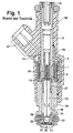
- 1 shows it Known electromagnetically actuated valve with two bow-shaped guide elements as external magnetic flux components
- Figure 2 shows a sheet metal blank as the basis for a 3 to be produced according to the invention Top view of a magnetic jacket according to the invention
- FIG. 4 a bottom view of this magnetic jacket
- Figure 5 a Sectional view of the magnetic jacket along the lines V-V in Figures 4 and 5
- Figure 6 a second Embodiment of a sheet metal blank for one Magnetic shell.
- Figure 1 is a known electromagnetically actuated Shown valve that belongs to the prior art and one Possibility of using one described later represents magnetic casing according to the invention. That in the figure 1 shown, for example, electromagnetically actuated Valve in the form of an injector for Fuel injection systems from mixture-compressing, spark-ignited internal combustion engines has one of one Solenoid 1 surrounded, as a fuel inlet port serving tubular core 2 as a so-called inner pole. On Coil body 3 receives a winding of the magnet coil 1.
- the core 2 extends up to a downstream core end 9 and further downstream, so that is arranged downstream of the bobbin 3 tubular connector, which in the further course as Valve seat carrier 10 is designated, in one piece with the core 2nd is formed, the entire component being a valve tube 12 referred to as.
- Valve seat support 10 also has a valve tube 12 tubular, but a much thinner wall than that Wall thicknesses of core 2 and valve seat support 10 having magnetic throttle point 13.
- it is the core 2 and the valve seat carrier 10 are also conceivable to be trained separately and in the area of the throttle point 13 provide non-magnetic intermediate part.
- the actuation the valve is electromagnetic in a known manner.
- a longitudinal bore 18 runs in the valve seat support 10, which are formed concentrically to a longitudinal valve axis 15 is.
- a longitudinal bore 18 In the longitudinal bore 18 is a z.
- tubular Valve needle 19 arranged at its downstream end 20 with a spherical valve closing body 21, on the Perimeter, for example, five flats 22 to flow past of the fuel are provided, for example by Welding is connected.
- valve seat support 10 For the axial movement of the valve needle 19 and thus for opening against the spring force of a return spring 25 or Closing the injector is used for electromagnetic Circle with the magnet coil 1, the core 2 and an armature 27.
- the armature 27 is connected to the valve closing body 21 opposite end of the valve needle 19 by a weld connected and aligned to the core 2.
- Valve seat support 10 In the downstream end of the core 2 facing away Valve seat support 10 is in the longitudinal bore 18 cylindrical valve seat body 29, which has a fixed Has valve seat, tightly assembled by welding.
- valve longitudinal axis 15 serves a guide opening 32 of the Valve seat body 29.
- the guide of the armature 27 is for example by guide lugs in the area of Throttle point 13 taken over.
- the spherical Valve closing body 21 interacts with the Flow direction frustoconical valve seat of the valve seat body 29 together.
- a cup-shaped, for example trained spray plate 34 firmly connected.
- the Spray plate 34 has at least one, for example four formed by eroding or stamping Spray orifices 35.
- the insertion depth of the valve seat body 29 with the Spray plate 34 determines the size of the stroke of the Valve needle 19.
- the one end position is the Valve needle 19 when the solenoid 1 is not energized by the System of the valve closing body 21 on the valve seat of the Valve seat body 29 set while the other End position of the valve needle 19 when the magnet coil 1 is excited results from the installation of the armature 17 at the core end 9.
- the magnet coil 1 is formed by two brackets and guiding elements 45 serving as ferromagnetic elements surround the magnetic coil 1 at least in the circumferential direction partially surrounded and with one end to the core 2 and the rest at the other end on the valve seat support 10 and with this z. B. connectable by welding, soldering or gluing are.
- the guide elements are in the valve according to the invention 45 by a magnetic jacket 60 produced according to the invention ( Figures 3 to 5) replaced.
- the installation position of the magnetic jacket 60 in axial and radial terms, however, is that of Guide elements 45 comparable, so that the Magnetic jacket 60 according to the invention, the magnet coil 1 in Partially surrounds the circumferential direction.
- the valve is largely with a plastic extrusion 50 enclosed, starting from the core 2 in axial Direction via solenoid 1 and instead of Guide elements 45 in the invention via the magnetic jacket 60 extends to the valve seat support 10, the Magnetic jacket 60 then completely axially and in, for example Circumferential direction is covered.
- To the plastic encapsulation 50 belongs, for example, to a co-molded electric Connector 52.
- a sheet metal blank 6 is shown, the Starting basis for the production of the magnetic jacket 60 forms.
- This sheet blank 6 is made from a larger sheet uniform thickness according to the required dimensions e.g. punched out. Then the sheet metal blank 6 is under Rolled a mandrel into the desired shape or bent so that it takes on a shape as shown in Figure 5 is shown. With the arrows 61 is the rolling movement indicated.
- Each individual sheet blank 6 for the production of a Magnetic jacket 60 is characterized by a specific Contouring out, with a division into three areas makes sense.
- a central area 63 ultimately a surrounding the magnetic coil 1 in the circumferential direction
- Sheath area 630 of the magnetic jacket 60 forms, close in the axial direction according to the installation in the valve on a first line of extension an upper and a lower edge area 64 and 65.
- the two edge areas 64 and 65 ultimately form attachment regions 640 and 650 of the magnetic jacket 60, with which an attachment to the core 2nd and is made possible on the valve seat support 10.
- the edge regions 64 and 65 are characterized in that they are segmented, meaning that of an upper one and lower boundary edge 66 and 67 starting from each several recesses 68 and 69 towards the middle Area 63 are introduced, the segments of the form respective edge region 64, 65.
- the recesses 68, 69 extend from the boundary edge 66, 67 for example, first with parallel side edges that face each other later converges to a pointed recess end 70, 71 stretch directionally.
- both edge areas 64, 65 are e.g. three recesses 68, 69 at the same distance from each other introduced so that the recesses 68 of the upper Edge area 64 exactly opposite the recesses 69 of the lower edge region 65 are formed.
- the two edge regions 64, 65 differ. While in the lower edge area 65 to the two outer Recesses 69 each again a complete segment connects and the lateral boundary edges 72 and 73 therefore have the contour of a half recess 69, are lateral boundary edges 72, 73 of the upper edge area 64 less than a segment width away from the two outer recesses 68 provided and also rectangular to the upper boundary edge 66. Compared to the lateral boundary edges 72, 73 of the edge regions 64, 65 are the lateral boundary edges 74 and 75 of the middle area 63 deepened, which after rolling the Sheet metal blank 6, the jacket area 630 of the magnetic jacket 60 has a window 80 ( Figure 5) through which Boundary edges 74, 75 is limited.
- the two Edge areas 64, 65 in perpendicular to the first Extension line extending second extension lines over the middle area 63 over.
- the recess ends 70, 71 of the recesses 68, 69 are approximately at the level of Transition shoulders of the lateral boundary edges 72, 73 to the boundary edges 74, 75 of the central region 63, since the later magnetic jacket 60 also in these areas Shoulders 78, 79 ( Figure 5) should have.
- the method of manufacturing the magnetic shell 60 is subdivided after the provision of the sheet metal blank 6 with the required contour in two essential steps.
- a first process step the entire sheet blank 6 e.g. rolled by means of a mandrel or bent until the two side Boundary edges 72, 73 of the lower edge region 65 face directly.
- a second Process step will be the upper and the lower Edge area 64, 65 e.g. with a clasp-like tool by deformation to a smaller outside diameter brought, the recesses 68, 69 to a minimum Width can be reduced so that the push the intervening segments closely together.
- the resulting fastening areas 640, 650 act Collet-like and can be easily opened during assembly become. Since the attachment areas 640, 650 under Are bias, the position of the magnetic jacket 60 at the assembly of the valve on the core 2 and the Valve seat bracket 10 already well fixed. As before mentioned, two shoulders 78, 79 ( Figure 5) arise as Transitional areas of the jacket area 630 to the two Attachment areas 640 and 650, the smaller one Have outer diameter than the jacket area 630. Die Recess ends 70, 71 are in the area of Shoulders 78, 79.
- Figure 3 is a plan view of the sheet metal blank 6 magnetic sheath produced according to FIG. 2 60 shown, while Figure 4 is a bottom view of this Magnetic jacket 60 shows.
- Figure 5 is in turn Sectional view of the magnetic jacket 60 along the lines V-V in FIGS. 4 and 5.
- FIG. 3 shows that the lateral boundary edges 72, 73 of the upper Edge area 64 are spaced apart so that on simple way coil pins of the magnet coil 1 through this existing space 81 axially from the magnetic jacket 60 can be performed.
- the sectional view according to FIG. 5 indicates that the Jacket area 630 does not completely revolve, but through the window 80 is interrupted.
- the size of the window 80 depends on the depth of the boundary edges 74, 75 of the middle area 63 on sheet metal blank 6.
- the window 80 can e.g. take a size of about 120 °, making a third of the circumference of the jacket region 630 is open. Because of this Window 80, the magnetic coil 1 is inserted radially, the is indicated schematically in Figure 5.
- the magnetic coil 1 can be inserted through the window 80 Jacket area 630 also in a simple manner be slightly bent.
- the window 80 can also from seen in the circumferential direction 120 ° larger or be made smaller.
- Figure 6 shows a second embodiment of a Sheet metal blank 6 for a magnetic jacket 60, which differs from that Sheet metal blank 6 according to Figure 2 differs in that both edge areas 64, 65 identical, but mirrored around the central area 63.
- the upper edge region 64 is thus also an example formed that the two outer recesses 68 up to the lateral boundary edge 72, 73 each connects a complete segment. Because in the rolled State of the magnetic jacket 60 thus no more space 81 is present, the coil pins of the magnetic coil 1 in this Fall led radially sideways out of the window 80.
- the invention is in no way related to fuel injectors limited, but generally affects everyone Electromagnetically operated valves of different types Application areas.
Landscapes
- Engineering & Computer Science (AREA)
- Physics & Mathematics (AREA)
- Electromagnetism (AREA)
- Chemical & Material Sciences (AREA)
- Combustion & Propulsion (AREA)
- Mechanical Engineering (AREA)
- General Engineering & Computer Science (AREA)
- Manufacturing & Machinery (AREA)
- Magnetically Actuated Valves (AREA)
- Fuel-Injection Apparatus (AREA)
- Electromagnets (AREA)
Claims (12)
- Vanne à commande électromagnétique, notamment injecteur de carburant pour des installations d'injection de carburant de moteurs à combustion interne, dotée d'un axe longitudinal de vanne (15), d'un circuit électromagnétique comprenant au moins une bobine magnétique (1), un noyau (2) servant de pôle intérieur et un induit (27), ainsi qu'une enveloppe magnétique (60) entourant au moins partiellement la bobine magnétique (1), l'ouverture et la fermeture de la vanne étant opérées par l'induit (27) sur un siège de vanne (29), et l'enveloppe magnétique (60) possédant une zone d'enveloppe médiane (630) à laquelle se raccordent des deux côtés des zones de fixation (640, 650) en sens axial, de diamètre inférieur à celui de la zone d'enveloppe (630), l'enveloppe magnétique (60) pouvant être fabriquée à partir d'une ébauche en tôle (6) par roulage ou cintrage,
caractérisée en ce que
les zones de fixation (640, 650) sont segmentées. - Vanne selon la revendication 1,
caractérisée en ce que
la zone d'enveloppe médiane (630) est interrompue dans le sens circonférentiel. - Vanne selon la revendication 2,
caractérisée en ce que
la zone d'enveloppe (630) tourne d'environ 240° et présente ainsi une fenêtre (80) d'environ 120°. - Vanne selon l'une quelconque des revendications précédentes,
caractérisée en ce que
la bobine magnétique (1) est logée dans un corps de bobine (3) et le corps de bobine (3) présente un diamètre extérieur plus grand que les deux zones de fixation (640, 650). - Vanne selon la revendication 1,
caractérisée en ce que
les zones de fixation (640, 650) comprennent chacune quatre segments situés entre les évidements (68, 69). - Vanne selon la revendication 5,
caractérisée en ce que
les évidements (68, 69) s'étendent axialement sur toute la longueur des zones de fixations (640, 650) et radialement sur toute l'épaisseur de matériau des zones de fixation (640, 650). - Vanne selon la revendication 1,
caractérisée en ce que
l'une des zones de fixation (640) de l'enveloppe magnétique (60) repose contre le noyau (2) et l'autre zone de fixation (650) contre un support de siège de vanne (10). - Procédé de fabrication d'une enveloppe magnétique pour une vanne, notamment pour une vanne à commande électromagnétique selon les revendications 1 à 7, l'enveloppe magnétique (60) entourant au moins partiellement une bobine magnétique (1),
caractérisé en ce quea) dans une première étape du procédé, une ébauche en tôle (6) est formée à partir d'une tôle, l'ébauche en tôle (6) comprenant une zone médiane (63) et deux zones de bord (64, 65) se faisant face raccordées à la zone (63) sur une première ligne de projection, et les zones de bord (64, 65) dépassent de la partie médiane (63) sur les deuxièmes lignes de projection perpendiculaires à la première ligne de projection, avec plusieurs évidements (68, 69) prévus dans les zones de bord (64, 65),b) dans une deuxième étape du procédé, l'ensemble de l'ébauche en tôle (6) est configurée dans une forme circulaire par roulage ou cintrage, etc) dans une troisième étape du procédé, les zones de bord (64, 65) sont formées avec un diamètre inférieur, les évidements (68, 69) étant réduits à une largeur minimale, de sorte qu'en fin de compte on obtient une enveloppe magnétique (60) qui a une zone d'enveloppe (630) médiane à laquelle se raccordent sur deux côtés opposés des zones de fixation (640, 650) d'un diamètre extérieur inférieur à la zone d'enveloppe (630). - Procédé selon la revendication 8,
caractérisé en ce que
l'ébauche en tôle (6) est déformée par estampage. - Procédé selon la revendication 8,
caractérisé en ce que
les évidements (68, 69) des zones de bord (64, 65) sont pratiqués de telle sorte que l'on a des bords latéraux d'abord parallèles en partant des bords de limitation (66, 67) de l'ébauche en tôle (6), qui s'étendent ensuite de manière convergente vers une extrémité pointue de l'évidement (70, 71). - Procédé selon la revendication 10,
caractérisé en ce que
des bords de limitation (72, 73) latéraux sur au moins une zone de bord (64, 65) en direction de la deuxième ligne de projection, ont un contour d'un demi-évidement (68, 69). - Procédé selon la revendication 10,
caractérisé en ce que
des bords de limitation (72, 73) latéraux sur au moins une zone de bord (64, 65) en direction de la deuxième ligne de projection, sont formés de telle sorte qu'ils se font face à distance l'un de l'autre après le roulage ou le cintrage.
Applications Claiming Priority (3)
| Application Number | Priority Date | Filing Date | Title |
|---|---|---|---|
| DE19860631 | 1998-12-29 | ||
| DE19860631A DE19860631A1 (de) | 1998-12-29 | 1998-12-29 | Elektromagnetisch betätigbares Ventil und Verfahren zur Herstellung eines Magnetmantels für ein Ventil |
| PCT/DE1999/003391 WO2000039448A1 (fr) | 1998-12-29 | 1999-10-22 | Vanne a commande electromagnetique et procede de fabrication d'une enveloppe magnetique pour vanne |
Publications (2)
| Publication Number | Publication Date |
|---|---|
| EP1068441A1 EP1068441A1 (fr) | 2001-01-17 |
| EP1068441B1 true EP1068441B1 (fr) | 2004-09-01 |
Family
ID=7893061
Family Applications (1)
| Application Number | Title | Priority Date | Filing Date |
|---|---|---|---|
| EP99960808A Expired - Lifetime EP1068441B1 (fr) | 1998-12-29 | 1999-10-22 | Vanne a commande electromagnetique et procede de fabrication d'une enveloppe magnetique pour vanne |
Country Status (9)
| Country | Link |
|---|---|
| US (2) | US6341759B1 (fr) |
| EP (1) | EP1068441B1 (fr) |
| JP (1) | JP2002533633A (fr) |
| KR (1) | KR20010041413A (fr) |
| CN (1) | CN1115478C (fr) |
| BR (1) | BR9908376A (fr) |
| DE (2) | DE19860631A1 (fr) |
| RU (1) | RU2239087C2 (fr) |
| WO (1) | WO2000039448A1 (fr) |
Families Citing this family (18)
| Publication number | Priority date | Publication date | Assignee | Title |
|---|---|---|---|---|
| WO2001000473A1 (fr) * | 1999-06-23 | 2001-01-04 | Continental Teves Ag & Co. Ohg | Soupape electromagnetique, notamment pour systemes de freinage hydrauliques a antiblocage |
| US6422486B1 (en) * | 2000-03-31 | 2002-07-23 | Siemens Automotive Corporation | Armature/needle assembly for a fuel injector and method of manufacturing same |
| US20050218249A1 (en) * | 2004-03-30 | 2005-10-06 | Denso Corporation | Electro-magnetic driver and fuel injection valve using the same |
| US7324419B2 (en) * | 2004-12-11 | 2008-01-29 | Hewlett-Packard Development Company, L.P. | Focus control via AC input signal |
| RU2286236C2 (ru) * | 2005-01-26 | 2006-10-27 | Федеральное государственное унитарное предприятие "Научно-производственное объединение прикладной механики им. акад. М.Ф. Решетнева" | Способ изготовления корпуса электромагнитного клапана |
| DE102006006031B4 (de) | 2005-04-20 | 2009-12-24 | Bürkert Werke GmbH & Co. KG | Elektromagneteinheit sowie Verfahren zur Herstellung einer solchen Elektromagneteinheit und eines Magnetgehäuses für eine solche Elektromagneteinheit |
| DE102007009963A1 (de) * | 2007-03-01 | 2008-09-04 | Robert Bosch Gmbh | Magnetkopf für Magnetventil |
| DE102008010976A1 (de) * | 2008-02-25 | 2009-08-27 | Robert Bosch Gmbh | Verfahren zum Richten eines langgestreckten Bauteils |
| US20100314568A1 (en) * | 2009-06-15 | 2010-12-16 | South Bend Controls, Inc. | Solenoid coil |
| JP5389560B2 (ja) * | 2009-07-23 | 2014-01-15 | 株式会社ケーヒン | 電磁式燃料噴射弁 |
| DE102009042889A1 (de) * | 2009-09-24 | 2011-06-09 | Hydraulik-Ring Gmbh | Cartridgeventil mit einer Buchse |
| DE102016208288A1 (de) * | 2016-05-13 | 2017-11-16 | Robert Bosch Gmbh | Injektor mit verbessertem Magnetaktor |
| EP3261102A1 (fr) | 2016-06-23 | 2017-12-27 | Rain Bird Corporation | Solénoïde universel |
| US10980120B2 (en) | 2017-06-15 | 2021-04-13 | Rain Bird Corporation | Compact printed circuit board |
| CN107091184A (zh) * | 2017-07-03 | 2017-08-25 | 东莞市盈森汽车电喷科技有限公司 | 喷油器高性能磁路结构 |
| DE102018200084B4 (de) | 2018-01-04 | 2021-09-16 | Vitesco Technologies GmbH | Verfahren zur Herstellung einer elektromagnetischen Ventilanordnung sowie elektromagnetische Ventilanordnung |
| US11503782B2 (en) | 2018-04-11 | 2022-11-22 | Rain Bird Corporation | Smart drip irrigation emitter |
| US11721465B2 (en) | 2020-04-24 | 2023-08-08 | Rain Bird Corporation | Solenoid apparatus and methods of assembly |
Family Cites Families (26)
| Publication number | Priority date | Publication date | Assignee | Title |
|---|---|---|---|---|
| US3593241A (en) * | 1969-07-18 | 1971-07-13 | Alfred J Ludwig | Solenoid valve having a slotted flux sleeve for nesting the winding leads |
| US3757262A (en) * | 1972-02-28 | 1973-09-04 | Rca Corp | Toroidal deflection yoke having conductors wound in flyback manner |
| DE3418436A1 (de) | 1984-05-18 | 1985-11-21 | Robert Bosch Gmbh, 7000 Stuttgart | Elektromagnetisch betaetigbares ventil und verfahren zur herstellung eines ventils |
| DE3825135A1 (de) | 1988-07-23 | 1990-01-25 | Bosch Gmbh Robert | Elektromagnetisch betaetigbares ventil |
| US5190223A (en) * | 1988-10-10 | 1993-03-02 | Siemens Automotive L.P. | Electromagnetic fuel injector with cartridge embodiment |
| DE3834444A1 (de) * | 1988-10-10 | 1990-04-12 | Mesenich Gerhard | Elektromagnetisches einspritzventil mit membranfeder |
| DE3834446A1 (de) * | 1988-10-10 | 1990-04-12 | Mesenich Gerhard | Elektromagnetisches einspritzventil in patronenbauweise |
| US4946107A (en) * | 1988-11-29 | 1990-08-07 | Pacer Industries, Inc. | Electromagnetic fuel injection valve |
| DE3904448A1 (de) | 1989-02-15 | 1990-08-16 | Bosch Gmbh Robert | Magnetanker |
| JPH07106394B2 (ja) * | 1989-05-17 | 1995-11-15 | 東洋製罐株式会社 | 絞りしごき缶の製造方法 |
| IT221658Z2 (it) * | 1989-10-17 | 1994-07-25 | Weber Srl | Perfezionamento alle valvole per la dosatura e la polverizzazione del carburante ad azionamento elettromagnetico per un dispositivo di ali- mentazione del carburante di un motore a combustione interna. |
| DE3934953A1 (de) * | 1989-10-20 | 1991-04-25 | Bosch Gmbh Robert | Magnetventil, insbesondere fuer kraftstoffeinspritzpumpen |
| DE4003229A1 (de) | 1990-02-03 | 1991-08-08 | Bosch Gmbh Robert | Elektromagnetisch betaetigbares ventil |
| DE4201448C2 (de) * | 1992-01-21 | 1995-03-16 | Danfoss As | Tauchanker-Magnetanordnung und Verfahren zu dessen Herstellung |
| RU2046673C1 (ru) * | 1992-03-27 | 1995-10-27 | Виктор Семенович Дегтярев | Форсунка для распыления жидкости |
| RU2059868C1 (ru) * | 1992-08-31 | 1996-05-10 | Фирма "Авангард" | Электромагнитная форсунка |
| RU2046519C1 (ru) * | 1992-12-30 | 1995-10-20 | Феликс Ильич Пинский | Электромагнитный привод |
| RU2080474C1 (ru) * | 1993-05-11 | 1997-05-27 | Исаак Матвеевич Коростышевский | Электромагнитная форсунка |
| RU2064074C1 (ru) * | 1993-06-08 | 1996-07-20 | Научно-технический центр Волжского объединения по производству легковых автомобилей | Электромагнитная форсунка |
| IT1264720B1 (it) * | 1993-10-26 | 1996-10-04 | Weber Srl | Valvola dosatrice e polverizzatrice di carburante ad azionamento elettromagnetico. |
| RU2052151C1 (ru) * | 1993-11-19 | 1996-01-10 | Владимир Маркович Коросташевский | Электромагнитная форсунка для впрыска топлива в двигатель внутреннего сгорания |
| US5394850A (en) * | 1993-11-19 | 1995-03-07 | Siemens Electric Limited | Top-feed fuel injector mounting in an integrated air-fuel system |
| DE4420176A1 (de) * | 1994-06-09 | 1995-12-14 | Bosch Gmbh Robert | Ventilnadel für ein elektromagnetisch betätigbares Ventil |
| US5544816A (en) | 1994-08-18 | 1996-08-13 | Siemens Automotive L.P. | Housing for coil of solenoid-operated fuel injector |
| RU2117815C1 (ru) * | 1996-02-13 | 1998-08-20 | Исаак Матвеевич Коростышевский | Электромагнитная форсунка |
| US6219903B1 (en) * | 1999-12-06 | 2001-04-24 | Eaton Corporation | Solenoid assembly with high-flux C-frame and method of making same |
-
1998
- 1998-12-29 DE DE19860631A patent/DE19860631A1/de not_active Withdrawn
-
1999
- 1999-10-22 WO PCT/DE1999/003391 patent/WO2000039448A1/fr not_active Ceased
- 1999-10-22 CN CN99803386A patent/CN1115478C/zh not_active Expired - Fee Related
- 1999-10-22 US US09/623,121 patent/US6341759B1/en not_active Expired - Fee Related
- 1999-10-22 JP JP2000591320A patent/JP2002533633A/ja not_active Withdrawn
- 1999-10-22 EP EP99960808A patent/EP1068441B1/fr not_active Expired - Lifetime
- 1999-10-22 RU RU2000124948/06A patent/RU2239087C2/ru not_active IP Right Cessation
- 1999-10-22 BR BR9908376-0A patent/BR9908376A/pt active Search and Examination
- 1999-10-22 KR KR1020007009547A patent/KR20010041413A/ko not_active Withdrawn
- 1999-10-22 DE DE59910397T patent/DE59910397D1/de not_active Expired - Fee Related
-
2001
- 2001-12-07 US US10/013,125 patent/US6745457B2/en not_active Expired - Fee Related
Also Published As
| Publication number | Publication date |
|---|---|
| BR9908376A (pt) | 2000-10-31 |
| US20020040524A1 (en) | 2002-04-11 |
| US6341759B1 (en) | 2002-01-29 |
| US6745457B2 (en) | 2004-06-08 |
| CN1292064A (zh) | 2001-04-18 |
| KR20010041413A (ko) | 2001-05-15 |
| DE59910397D1 (de) | 2004-10-07 |
| CN1115478C (zh) | 2003-07-23 |
| EP1068441A1 (fr) | 2001-01-17 |
| RU2239087C2 (ru) | 2004-10-27 |
| JP2002533633A (ja) | 2002-10-08 |
| WO2000039448A1 (fr) | 2000-07-06 |
| DE19860631A1 (de) | 2000-07-06 |
Similar Documents
| Publication | Publication Date | Title |
|---|---|---|
| EP0685643B1 (fr) | Pointeau pour une soupape à commande électromagnétique | |
| DE19722720C2 (de) | Kraftstoffinjektor mit vereinfachter Bauweise und vereinfachtem Zusammenbau | |
| EP0358922B1 (fr) | Soupape électromagnétique | |
| EP0877860B1 (fr) | Soupape d'injection de carburant | |
| EP0865574B1 (fr) | Soupape d'injection de carburant et son procede de fabrication | |
| EP0733162B1 (fr) | Procede de production d'un circuit magnetique pour soupape | |
| DE19860631A1 (de) | Elektromagnetisch betätigbares Ventil und Verfahren zur Herstellung eines Magnetmantels für ein Ventil | |
| EP0717816B1 (fr) | Soupape a commande electromagnetique | |
| DE4109868A1 (de) | Einstellbuchse fuer ein elektromagnetisch betaetigbares ventil und verfahren zur herstellung | |
| WO1996003579A1 (fr) | Pointeau pour soupape a actionnement electromagnetique et son procede de production | |
| EP1062421B1 (fr) | Soupape d'injection de carburant | |
| DE4137994A1 (de) | Elektromagnetisch betaetigbares einspritzventil mit einem duesentraeger und verfahren zur herstellung eines duesentraegers eines einspritzventils | |
| EP1919655B1 (fr) | Procede pour realiser une cage solide | |
| DE4445358A1 (de) | Ventil und Verfahren zur Herstellung eines Ventiles | |
| EP0383063B1 (fr) | Armature d'aimant | |
| EP1877660B1 (fr) | Soupape d'injection de carburant et son procede de montage | |
| DE69505403T2 (de) | Winkelige anschlussklemme/-wicklung-gestaltung für kraftstoffeinspritzventil mit kleinem durchmesser | |
| EP0383064A1 (fr) | Armature d'aimant | |
| WO2007023125A1 (fr) | Procede pour produire un boitier rigide | |
| EP1699578B1 (fr) | Procede de production d'un boitier en forme de manchon, a partir de plusieurs toles plates | |
| EP1366283B1 (fr) | Soupape d'injection de carburant munie d'un manchon de reglage | |
| DE69808787T2 (de) | Kraftfahrzeugregelventil mit zweiteiligem magnetpolstück | |
| EP0925441B1 (fr) | Soupape a commande electromagnetique | |
| EP2866970B1 (fr) | Procédé pour la fabrication d'un carter, en particulier d'un carter pour soupape | |
| DE4108665C2 (de) | Einstellbuchse für ein elektromagnetisch betätigbares Ventil |
Legal Events
| Date | Code | Title | Description |
|---|---|---|---|
| PUAI | Public reference made under article 153(3) epc to a published international application that has entered the european phase |
Free format text: ORIGINAL CODE: 0009012 |
|
| AK | Designated contracting states |
Kind code of ref document: A1 Designated state(s): AT BE CH CY DE DK ES FI FR GB GR IE IT LI LU MC NL PT SE |
|
| 17P | Request for examination filed |
Effective date: 20010108 |
|
| 17Q | First examination report despatched |
Effective date: 20030715 |
|
| GRAP | Despatch of communication of intention to grant a patent |
Free format text: ORIGINAL CODE: EPIDOSNIGR1 |
|
| GRAS | Grant fee paid |
Free format text: ORIGINAL CODE: EPIDOSNIGR3 |
|
| GRAA | (expected) grant |
Free format text: ORIGINAL CODE: 0009210 |
|
| AK | Designated contracting states |
Kind code of ref document: B1 Designated state(s): DE FR GB IT |
|
| REG | Reference to a national code |
Ref country code: GB Ref legal event code: FG4D Free format text: NOT ENGLISH |
|
| REG | Reference to a national code |
Ref country code: IE Ref legal event code: FG4D Free format text: GERMAN |
|
| REF | Corresponds to: |
Ref document number: 59910397 Country of ref document: DE Date of ref document: 20041007 Kind code of ref document: P |
|
| PGFP | Annual fee paid to national office [announced via postgrant information from national office to epo] |
Ref country code: GB Payment date: 20041008 Year of fee payment: 6 |
|
| GBT | Gb: translation of ep patent filed (gb section 77(6)(a)/1977) | ||
| REG | Reference to a national code |
Ref country code: IE Ref legal event code: FD4D |
|
| PLBE | No opposition filed within time limit |
Free format text: ORIGINAL CODE: 0009261 |
|
| STAA | Information on the status of an ep patent application or granted ep patent |
Free format text: STATUS: NO OPPOSITION FILED WITHIN TIME LIMIT |
|
| ET | Fr: translation filed | ||
| 26N | No opposition filed |
Effective date: 20050602 |
|
| PG25 | Lapsed in a contracting state [announced via postgrant information from national office to epo] |
Ref country code: GB Free format text: LAPSE BECAUSE OF NON-PAYMENT OF DUE FEES Effective date: 20051022 |
|
| GBPC | Gb: european patent ceased through non-payment of renewal fee |
Effective date: 20051022 |
|
| REG | Reference to a national code |
Ref country code: FR Ref legal event code: ST Effective date: 20080630 |
|
| PGFP | Annual fee paid to national office [announced via postgrant information from national office to epo] |
Ref country code: FR Payment date: 20061020 Year of fee payment: 8 |
|
| PGFP | Annual fee paid to national office [announced via postgrant information from national office to epo] |
Ref country code: IT Payment date: 20081028 Year of fee payment: 10 |
|
| PG25 | Lapsed in a contracting state [announced via postgrant information from national office to epo] |
Ref country code: FR Free format text: LAPSE BECAUSE OF NON-PAYMENT OF DUE FEES Effective date: 20071031 |
|
| PGFP | Annual fee paid to national office [announced via postgrant information from national office to epo] |
Ref country code: DE Payment date: 20081222 Year of fee payment: 10 |
|
| PG25 | Lapsed in a contracting state [announced via postgrant information from national office to epo] |
Ref country code: DE Free format text: LAPSE BECAUSE OF NON-PAYMENT OF DUE FEES Effective date: 20100501 |
|
| PG25 | Lapsed in a contracting state [announced via postgrant information from national office to epo] |
Ref country code: IT Free format text: LAPSE BECAUSE OF NON-PAYMENT OF DUE FEES Effective date: 20091022 |