EP1068458B1 - Verbindungseinrichtung zum verbinden zweier bauteile, kombination der verbindungseinrichtung mit den beiden bauteilen und verfahren zur herstellung einer verbindung zwischen zwei bauteilen - Google Patents
Verbindungseinrichtung zum verbinden zweier bauteile, kombination der verbindungseinrichtung mit den beiden bauteilen und verfahren zur herstellung einer verbindung zwischen zwei bauteilen Download PDFInfo
- Publication number
- EP1068458B1 EP1068458B1 EP99919174A EP99919174A EP1068458B1 EP 1068458 B1 EP1068458 B1 EP 1068458B1 EP 99919174 A EP99919174 A EP 99919174A EP 99919174 A EP99919174 A EP 99919174A EP 1068458 B1 EP1068458 B1 EP 1068458B1
- Authority
- EP
- European Patent Office
- Prior art keywords
- component
- fastener device
- accordance
- joint
- fastener
- Prior art date
- Legal status (The legal status is an assumption and is not a legal conclusion. Google has not performed a legal analysis and makes no representation as to the accuracy of the status listed.)
- Expired - Lifetime
Links
- 238000005304 joining Methods 0.000 title claims description 12
- 238000004519 manufacturing process Methods 0.000 title claims description 6
- 239000002184 metal Substances 0.000 claims description 55
- 125000006850 spacer group Chemical group 0.000 claims description 53
- 238000000034 method Methods 0.000 claims description 34
- 238000004080 punching Methods 0.000 claims description 30
- 238000013461 design Methods 0.000 claims description 11
- 238000003780 insertion Methods 0.000 claims description 10
- 230000037431 insertion Effects 0.000 claims description 10
- 239000000853 adhesive Substances 0.000 claims description 3
- 230000001070 adhesive effect Effects 0.000 claims description 3
- 210000003128 head Anatomy 0.000 claims 7
- 210000001331 nose Anatomy 0.000 claims 2
- 239000007787 solid Substances 0.000 claims 2
- 230000014759 maintenance of location Effects 0.000 claims 1
- 238000012549 training Methods 0.000 description 13
- 238000005516 engineering process Methods 0.000 description 6
- 239000000463 material Substances 0.000 description 6
- 238000003466 welding Methods 0.000 description 6
- 230000008901 benefit Effects 0.000 description 5
- 238000004026 adhesive bonding Methods 0.000 description 3
- 238000003825 pressing Methods 0.000 description 3
- 230000015572 biosynthetic process Effects 0.000 description 2
- 239000002131 composite material Substances 0.000 description 2
- 238000009434 installation Methods 0.000 description 2
- 238000012545 processing Methods 0.000 description 2
- 238000003860 storage Methods 0.000 description 2
- 230000007704 transition Effects 0.000 description 2
- 241001136792 Alle Species 0.000 description 1
- 239000006096 absorbing agent Substances 0.000 description 1
- 239000000956 alloy Substances 0.000 description 1
- 229910045601 alloy Inorganic materials 0.000 description 1
- 150000001875 compounds Chemical class 0.000 description 1
- 230000006835 compression Effects 0.000 description 1
- 238000007906 compression Methods 0.000 description 1
- 238000010276 construction Methods 0.000 description 1
- 238000011161 development Methods 0.000 description 1
- 238000012986 modification Methods 0.000 description 1
- 230000004048 modification Effects 0.000 description 1
- 238000000465 moulding Methods 0.000 description 1
- 238000002360 preparation method Methods 0.000 description 1
- 239000012945 sealing adhesive Substances 0.000 description 1
- 230000035939 shock Effects 0.000 description 1
- 230000003068 static effect Effects 0.000 description 1
Images







Classifications
-
- F—MECHANICAL ENGINEERING; LIGHTING; HEATING; WEAPONS; BLASTING
- F16—ENGINEERING ELEMENTS AND UNITS; GENERAL MEASURES FOR PRODUCING AND MAINTAINING EFFECTIVE FUNCTIONING OF MACHINES OR INSTALLATIONS; THERMAL INSULATION IN GENERAL
- F16B—DEVICES FOR FASTENING OR SECURING CONSTRUCTIONAL ELEMENTS OR MACHINE PARTS TOGETHER, e.g. NAILS, BOLTS, CIRCLIPS, CLAMPS, CLIPS OR WEDGES; JOINTS OR JOINTING
- F16B5/00—Joining sheets or plates, e.g. panels, to one another or to strips or bars parallel to them
- F16B5/02—Joining sheets or plates, e.g. panels, to one another or to strips or bars parallel to them by means of fastening members using screw-thread
-
- F—MECHANICAL ENGINEERING; LIGHTING; HEATING; WEAPONS; BLASTING
- F16—ENGINEERING ELEMENTS AND UNITS; GENERAL MEASURES FOR PRODUCING AND MAINTAINING EFFECTIVE FUNCTIONING OF MACHINES OR INSTALLATIONS; THERMAL INSULATION IN GENERAL
- F16B—DEVICES FOR FASTENING OR SECURING CONSTRUCTIONAL ELEMENTS OR MACHINE PARTS TOGETHER, e.g. NAILS, BOLTS, CIRCLIPS, CLAMPS, CLIPS OR WEDGES; JOINTS OR JOINTING
- F16B19/00—Bolts without screw-thread; Pins, including deformable elements; Rivets
- F16B19/04—Rivets; Spigots or the like fastened by riveting
-
- F—MECHANICAL ENGINEERING; LIGHTING; HEATING; WEAPONS; BLASTING
- F16—ENGINEERING ELEMENTS AND UNITS; GENERAL MEASURES FOR PRODUCING AND MAINTAINING EFFECTIVE FUNCTIONING OF MACHINES OR INSTALLATIONS; THERMAL INSULATION IN GENERAL
- F16B—DEVICES FOR FASTENING OR SECURING CONSTRUCTIONAL ELEMENTS OR MACHINE PARTS TOGETHER, e.g. NAILS, BOLTS, CIRCLIPS, CLAMPS, CLIPS OR WEDGES; JOINTS OR JOINTING
- F16B37/00—Nuts or like thread-engaging members
- F16B37/04—Devices for fastening nuts to surfaces, e.g. sheets, plates
- F16B37/06—Devices for fastening nuts to surfaces, e.g. sheets, plates by means of welding or riveting
- F16B37/062—Devices for fastening nuts to surfaces, e.g. sheets, plates by means of welding or riveting by means of riveting
-
- F—MECHANICAL ENGINEERING; LIGHTING; HEATING; WEAPONS; BLASTING
- F16—ENGINEERING ELEMENTS AND UNITS; GENERAL MEASURES FOR PRODUCING AND MAINTAINING EFFECTIVE FUNCTIONING OF MACHINES OR INSTALLATIONS; THERMAL INSULATION IN GENERAL
- F16B—DEVICES FOR FASTENING OR SECURING CONSTRUCTIONAL ELEMENTS OR MACHINE PARTS TOGETHER, e.g. NAILS, BOLTS, CIRCLIPS, CLAMPS, CLIPS OR WEDGES; JOINTS OR JOINTING
- F16B5/00—Joining sheets or plates, e.g. panels, to one another or to strips or bars parallel to them
- F16B5/04—Joining sheets or plates, e.g. panels, to one another or to strips or bars parallel to them by means of riveting
-
- F—MECHANICAL ENGINEERING; LIGHTING; HEATING; WEAPONS; BLASTING
- F16—ENGINEERING ELEMENTS AND UNITS; GENERAL MEASURES FOR PRODUCING AND MAINTAINING EFFECTIVE FUNCTIONING OF MACHINES OR INSTALLATIONS; THERMAL INSULATION IN GENERAL
- F16B—DEVICES FOR FASTENING OR SECURING CONSTRUCTIONAL ELEMENTS OR MACHINE PARTS TOGETHER, e.g. NAILS, BOLTS, CIRCLIPS, CLAMPS, CLIPS OR WEDGES; JOINTS OR JOINTING
- F16B19/00—Bolts without screw-thread; Pins, including deformable elements; Rivets
- F16B19/02—Bolts or sleeves for positioning of machine parts, e.g. notched taper pins, fitting pins, sleeves, eccentric positioning rings
-
- F—MECHANICAL ENGINEERING; LIGHTING; HEATING; WEAPONS; BLASTING
- F16—ENGINEERING ELEMENTS AND UNITS; GENERAL MEASURES FOR PRODUCING AND MAINTAINING EFFECTIVE FUNCTIONING OF MACHINES OR INSTALLATIONS; THERMAL INSULATION IN GENERAL
- F16B—DEVICES FOR FASTENING OR SECURING CONSTRUCTIONAL ELEMENTS OR MACHINE PARTS TOGETHER, e.g. NAILS, BOLTS, CIRCLIPS, CLAMPS, CLIPS OR WEDGES; JOINTS OR JOINTING
- F16B37/00—Nuts or like thread-engaging members
- F16B37/04—Devices for fastening nuts to surfaces, e.g. sheets, plates
- F16B37/06—Devices for fastening nuts to surfaces, e.g. sheets, plates by means of welding or riveting
- F16B37/062—Devices for fastening nuts to surfaces, e.g. sheets, plates by means of welding or riveting by means of riveting
- F16B37/065—Devices for fastening nuts to surfaces, e.g. sheets, plates by means of welding or riveting by means of riveting by deforming the material of the nut
-
- Y—GENERAL TAGGING OF NEW TECHNOLOGICAL DEVELOPMENTS; GENERAL TAGGING OF CROSS-SECTIONAL TECHNOLOGIES SPANNING OVER SEVERAL SECTIONS OF THE IPC; TECHNICAL SUBJECTS COVERED BY FORMER USPC CROSS-REFERENCE ART COLLECTIONS [XRACs] AND DIGESTS
- Y10—TECHNICAL SUBJECTS COVERED BY FORMER USPC
- Y10T—TECHNICAL SUBJECTS COVERED BY FORMER US CLASSIFICATION
- Y10T29/00—Metal working
- Y10T29/49—Method of mechanical manufacture
- Y10T29/49616—Structural member making
-
- Y—GENERAL TAGGING OF NEW TECHNOLOGICAL DEVELOPMENTS; GENERAL TAGGING OF CROSS-SECTIONAL TECHNOLOGIES SPANNING OVER SEVERAL SECTIONS OF THE IPC; TECHNICAL SUBJECTS COVERED BY FORMER USPC CROSS-REFERENCE ART COLLECTIONS [XRACs] AND DIGESTS
- Y10—TECHNICAL SUBJECTS COVERED BY FORMER USPC
- Y10T—TECHNICAL SUBJECTS COVERED BY FORMER US CLASSIFICATION
- Y10T29/00—Metal working
- Y10T29/49—Method of mechanical manufacture
- Y10T29/49826—Assembling or joining
- Y10T29/49908—Joining by deforming
- Y10T29/49915—Overedge assembling of seated part
-
- Y—GENERAL TAGGING OF NEW TECHNOLOGICAL DEVELOPMENTS; GENERAL TAGGING OF CROSS-SECTIONAL TECHNOLOGIES SPANNING OVER SEVERAL SECTIONS OF THE IPC; TECHNICAL SUBJECTS COVERED BY FORMER USPC CROSS-REFERENCE ART COLLECTIONS [XRACs] AND DIGESTS
- Y10—TECHNICAL SUBJECTS COVERED BY FORMER USPC
- Y10T—TECHNICAL SUBJECTS COVERED BY FORMER US CLASSIFICATION
- Y10T29/00—Metal working
- Y10T29/49—Method of mechanical manufacture
- Y10T29/49826—Assembling or joining
- Y10T29/49908—Joining by deforming
- Y10T29/49915—Overedge assembling of seated part
- Y10T29/4992—Overedge assembling of seated part by flaring inserted cup or tube end
-
- Y—GENERAL TAGGING OF NEW TECHNOLOGICAL DEVELOPMENTS; GENERAL TAGGING OF CROSS-SECTIONAL TECHNOLOGIES SPANNING OVER SEVERAL SECTIONS OF THE IPC; TECHNICAL SUBJECTS COVERED BY FORMER USPC CROSS-REFERENCE ART COLLECTIONS [XRACs] AND DIGESTS
- Y10—TECHNICAL SUBJECTS COVERED BY FORMER USPC
- Y10T—TECHNICAL SUBJECTS COVERED BY FORMER US CLASSIFICATION
- Y10T29/00—Metal working
- Y10T29/49—Method of mechanical manufacture
- Y10T29/49826—Assembling or joining
- Y10T29/49908—Joining by deforming
- Y10T29/49938—Radially expanding part in cavity, aperture, or hollow body
- Y10T29/49943—Riveting
-
- Y—GENERAL TAGGING OF NEW TECHNOLOGICAL DEVELOPMENTS; GENERAL TAGGING OF CROSS-SECTIONAL TECHNOLOGIES SPANNING OVER SEVERAL SECTIONS OF THE IPC; TECHNICAL SUBJECTS COVERED BY FORMER USPC CROSS-REFERENCE ART COLLECTIONS [XRACs] AND DIGESTS
- Y10—TECHNICAL SUBJECTS COVERED BY FORMER USPC
- Y10T—TECHNICAL SUBJECTS COVERED BY FORMER US CLASSIFICATION
- Y10T29/00—Metal working
- Y10T29/49—Method of mechanical manufacture
- Y10T29/49826—Assembling or joining
- Y10T29/49947—Assembling or joining by applying separate fastener
- Y10T29/49954—Fastener deformed after application
-
- Y—GENERAL TAGGING OF NEW TECHNOLOGICAL DEVELOPMENTS; GENERAL TAGGING OF CROSS-SECTIONAL TECHNOLOGIES SPANNING OVER SEVERAL SECTIONS OF THE IPC; TECHNICAL SUBJECTS COVERED BY FORMER USPC CROSS-REFERENCE ART COLLECTIONS [XRACs] AND DIGESTS
- Y10—TECHNICAL SUBJECTS COVERED BY FORMER USPC
- Y10T—TECHNICAL SUBJECTS COVERED BY FORMER US CLASSIFICATION
- Y10T29/00—Metal working
- Y10T29/49—Method of mechanical manufacture
- Y10T29/49826—Assembling or joining
- Y10T29/49947—Assembling or joining by applying separate fastener
- Y10T29/49954—Fastener deformed after application
- Y10T29/49956—Riveting
-
- Y—GENERAL TAGGING OF NEW TECHNOLOGICAL DEVELOPMENTS; GENERAL TAGGING OF CROSS-SECTIONAL TECHNOLOGIES SPANNING OVER SEVERAL SECTIONS OF THE IPC; TECHNICAL SUBJECTS COVERED BY FORMER USPC CROSS-REFERENCE ART COLLECTIONS [XRACs] AND DIGESTS
- Y10—TECHNICAL SUBJECTS COVERED BY FORMER USPC
- Y10T—TECHNICAL SUBJECTS COVERED BY FORMER US CLASSIFICATION
- Y10T29/00—Metal working
- Y10T29/49—Method of mechanical manufacture
- Y10T29/49826—Assembling or joining
- Y10T29/49947—Assembling or joining by applying separate fastener
- Y10T29/49966—Assembling or joining by applying separate fastener with supplemental joining
-
- Y—GENERAL TAGGING OF NEW TECHNOLOGICAL DEVELOPMENTS; GENERAL TAGGING OF CROSS-SECTIONAL TECHNOLOGIES SPANNING OVER SEVERAL SECTIONS OF THE IPC; TECHNICAL SUBJECTS COVERED BY FORMER USPC CROSS-REFERENCE ART COLLECTIONS [XRACs] AND DIGESTS
- Y10—TECHNICAL SUBJECTS COVERED BY FORMER USPC
- Y10T—TECHNICAL SUBJECTS COVERED BY FORMER US CLASSIFICATION
- Y10T403/00—Joints and connections
- Y10T403/33—Transverse rod to spaced plate surfaces
-
- Y—GENERAL TAGGING OF NEW TECHNOLOGICAL DEVELOPMENTS; GENERAL TAGGING OF CROSS-SECTIONAL TECHNOLOGIES SPANNING OVER SEVERAL SECTIONS OF THE IPC; TECHNICAL SUBJECTS COVERED BY FORMER USPC CROSS-REFERENCE ART COLLECTIONS [XRACs] AND DIGESTS
- Y10—TECHNICAL SUBJECTS COVERED BY FORMER USPC
- Y10T—TECHNICAL SUBJECTS COVERED BY FORMER US CLASSIFICATION
- Y10T403/00—Joints and connections
- Y10T403/33—Transverse rod to spaced plate surfaces
- Y10T403/335—Retainer utilizes or abuts plural plates
-
- Y—GENERAL TAGGING OF NEW TECHNOLOGICAL DEVELOPMENTS; GENERAL TAGGING OF CROSS-SECTIONAL TECHNOLOGIES SPANNING OVER SEVERAL SECTIONS OF THE IPC; TECHNICAL SUBJECTS COVERED BY FORMER USPC CROSS-REFERENCE ART COLLECTIONS [XRACs] AND DIGESTS
- Y10—TECHNICAL SUBJECTS COVERED BY FORMER USPC
- Y10T—TECHNICAL SUBJECTS COVERED BY FORMER US CLASSIFICATION
- Y10T403/00—Joints and connections
- Y10T403/49—Member deformed in situ
- Y10T403/4949—Deforming component is inserted section
-
- Y—GENERAL TAGGING OF NEW TECHNOLOGICAL DEVELOPMENTS; GENERAL TAGGING OF CROSS-SECTIONAL TECHNOLOGIES SPANNING OVER SEVERAL SECTIONS OF THE IPC; TECHNICAL SUBJECTS COVERED BY FORMER USPC CROSS-REFERENCE ART COLLECTIONS [XRACs] AND DIGESTS
- Y10—TECHNICAL SUBJECTS COVERED BY FORMER USPC
- Y10T—TECHNICAL SUBJECTS COVERED BY FORMER US CLASSIFICATION
- Y10T403/00—Joints and connections
- Y10T403/75—Joints and connections having a joining piece extending through aligned openings in plural members
Definitions
- the present invention relates to a connecting device, at one end via a connection that can be formed by forming, preferably a rivet connection, attached to a first component or is attachable, and has a receiving area for receiving a bolt, nut or other element, for example a bayonet part or a shaft is designed or can be designed.
- the present invention further relates to a combination of such Connection device with one, two or three components and a method to establish a connection between a first and second component using such a connecting device.
- a connecting device of the type mentioned is made of several Writings known.
- the European patent discloses 0 539 793 a nut element, which in a component, in particular in a Sheet metal part by means of a process known as clamping riveting can be introduced non-positively.
- the Germans Patents P 30 03 908 and P 34 47 006 punch bolts known introduced into a component in the form of a sheet metal part in a self-punching manner can be, the shape features, the so-called Form stamping and riveting section of the bolt element on which Shank part of the bolt element facing away from the head provided are, so that after insertion of the bolt element from one side into a Component of the shaft part of the bolt element on this side of Sheet metal part extends away.
- Bolt elements are also known which can be used in a pre-perforated component are and via a connection that can be formed in the forming process Area immediately below the head of the bolt element with the Component can be attached.
- Such bolt elements are for example in the German patent application P 44 10 475 described. But you can also be self-punching, such as in German Patent application of the applicant 195 35 537.7 specified.
- EBF bolt or self-piercing EBF bolt after completion of the connection with the component, the head of the bolt element arranged on one side of the component, the shaft part with thread is on the other side of the component.
- All of the aforementioned joining elements are those which are described in a sheet metal part or, if necessary, inserted into several sheet metal parts lying against each other and then screwing on another sheet metal part enable. It is screwed on using a bolt or a Mother, the or in a formed as a nut member or screwed or screwed onto a joining element designed as a bolt becomes.
- the object of the present invention is a connecting device to be provided that deal with conventional sheet metal processing can easily connect, which is inexpensive to run and which is a highly stable attachment of a third component to one of the first and second component and the connecting device existing Can produce composite part.
- a connecting device is used to achieve this object of the type mentioned at the outset, which is distinguished by that they are in a region spaced apart from the former end is designed for attachment to or in a second component, wherein after completion of a connection with the first component and after Attachment of the second component to the receiving area another component.
- the spaced area can at the first opposite end of the connecting device be provided. But it can also be in the middle, for example of the connector so that the other end of the connector protrudes beyond the second component.
- connection device in the spaced area can advantageously be used as a blind rivet sleeve be designed. But it can also be used for forming be designed for the second component, depending on the specific training. Finally, it would also be possible to design the spaced area so that it is for welding or gluing to the second component suitable.
- the connecting device can be made in one part or in several parts become.
- the one-piece design is easy to use on the one hand, has the disadvantage, however, that the length of the connecting device always has to be adapted to the respective purpose, what the storage difficult.
- a multi-part design allows such storage problems to get under control - for example, that the two Ends of the connecting device through standard joining elements are formed, each in terms of forming technology with the associated Sheet metal part can be connected while a as a spacer tube middle section to be designated in different lengths depending on the application can be made.
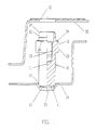
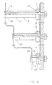
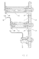
- FIG. 1 shows a connecting device 10 according to the invention, their first, lower end 12 via a connection that can be produced by molding 11 with a first component 14 in the form of a sheet metal part is.
- the connection made by metal forming was carried out on this Embodiment according to the German patent P 34 47 006. That means that the one-piece connecting device 10 on their lower, first end has a training corresponding to So-called SBF (punching bolt with flange) version from Profil Connection Technology GmbH & Co. KG (hereinafter called Profil), which at the punching and riveting with the component 14 to that in FIG. 1 shown connection leads.
- Profil Profil
- Radially extending lugs 16 which prevent rotation form between the connecting device 10 and the first component 14.
- the upper end 18 of the connector 10 therefore the shape of a nut element with a flange part 20 and with a stamping and riveting section 22 which extends over a substantially radially extending shoulder 24 merges into the flange 20, wherein here, too, anti-rotation features 26 are provided in the region of the shoulder are.
- the top end 18 of the connector is self-locking Training in the form of the punching and riveting section 22 provided is in this embodiment, the punching and riveting section not used for punching, but instead it is also pre-punched as a sheet metal molded part 30.
- the hole is shown at 32 and is coaxial to the longitudinal axis 31 of the connecting device 10 and the lower forming connection 11 with the first component 14.
- the second reason why the punching and riveting section 22 is not here Punching the hole 32 is that it is self-punching Function normally only used for sheet thicknesses up to 2 mm becomes.
- the second component 30 formed from two sheets, one on top of the other, with a total thickness of more than 2 mm.
- the rounded drawing edge 34 of the punching and riveting section serves namely to align the second component 30 with the first component 14.
- a connecting device 10 is provided but a second or more, further connection devices, which are arranged at spaced apart locations. These can then take on the task of the two components 14 and 30 align each other.
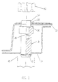
- FIG. 2 shows the position after the alignment of the two components 14 and 30 to each other and also shows a die 40, which is below the first Component 14 is arranged, and an upper die 42, which is in the stamp of a Set head is arranged and for riveting the punching and riveting section 22 is used with the second component 30.
- This die 42 is not described here since it is well known per se is due to the popularity of the RSF elements. The corresponding The procedure is otherwise for the RSF parent element in the German Patent 36 10 675 described in detail.
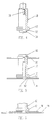
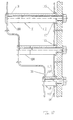
- Fig. 4 shows a partially sectioned view of a another connecting device 10, the upper end of which corresponds in principle the lower end of the connecting device 10 of FIG. 1 Execution is formed, but only with the difference that the upper end, like the whole connecting device 10, is hollow and one Has threaded cylinder 28.
- the lower end 12 of the connector 4 in this example corresponds to an RSN parent element trained by Profil, i.e. according to the mother element according to European patent 0 539 739, which is why the exact Training of the corresponding shape features are not described here becomes.
- the nut element-like design at the lower end 12 of the connecting device 10 of FIG. 4 is of a somewhat larger size Diameter, i.e. essentially according to the so-called RND mother elements from Profil.
- connection of the lower end 12 of the connecting device 10 with the first component 14 is shown in FIG. 5.
- the cone-shaped collar 50 When carrying out the clamp hole riveting process, the cone-shaped collar 50 set somewhat steeper and during the joining process pressed flatter, creating a high-quality joint.
- the anti-rotation lugs not shown here, but available ensure that the connector 10 is twisted compared to the sheet metal part 14 does not occur when a screw is inserted.
- Fig. 5 also shows the connection between the upper end 18 of the 4 with the second component 30. This Connection is essentially identical to the training on lower end 12 of FIG. 1, but with one exception.
- the sheet metal part 14 is pre-punched. After Implementation of this connection, i.e. at the first lower end of the connector 10 then becomes the second component 30 over the undeformed stamping and riveting section 22 of the connecting device 10 of FIG. 4 and then flanged, as shown in FIG. 5. Since the component 30 is pre-punched here, there is no punching slug in contrast to the training in the lower part of Fig. 1. However, it would be quite possible, the self-punching function of the punching and riveting section 22 of the connecting device 10 of FIG. 4, whereby then a punching slug would result, which is the upper end 18 of the connecting device 10 would close according to FIG. 5. The punching slug can, however, if desired, be removed using a plunger that is passed through the hollow connecting device 10.
- Fig. 6 only shows that the connecting device 10 also on one Component can be attached in the region of the lower end 12, the consists of two sheet layers 56 and 58. Also the technical connection in the area of the upper end 18 of the connecting device 10 can - if desired - be carried out with two or more sheet layers become.
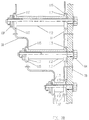
- Fig. 7 now shows three connecting devices 10, the corresponding 4, but three have different lengths.
- connection devices 10 are shown in FIG Fig. 7 in different areas of the two components 14 and 30 at a distance introduced from each other, creating a step-like formation is present. This training is indeed feasible, but has been chosen more to the different lengths of the different Clarify connection devices 10.
- FIG. 7 also shows how a third component 60 is attached to the assembly part 62 of FIG. 7 is fastened here, namely via three screws 64, wherein the head part 66 of each bolt 64 abuts the third component 60 and the Shaft part 67 through the third component 60 and the first component 14 and partially extends through the connecting device 10 and the thread 68 each bolt 64 in the threaded cylinder 28 of the respective connection device 10 is screwed.
- each connector 10 is exactly rectangular to the first component 14. Due to the comparatively large diameter of part 52 is also the connection in the area of the first component easily capable of static and shear moments and record dynamically.
- the connection in the deformed area Rivet section 54 serves on the one hand to secure expression, on the other hand the anti-rotation of the connecting device 10 with respect to the first Component 14.
- the rivet section 22 at the second end 18 of the connecting device 10 secures when the second component 30 is assembled with the first component 14 high quality centering and positioning of the second component 30 compared to the first component 14.
- the anti-rotation lugs in the shoulder area around the punching and riveting section 22 increase the security against rotation of the connection between the connecting devices and the two components. For the rest is also the Connection in the area of the end 18 capable of shear and compressive forces take.
- connection with the first component 14 as well as in the forming technology Connection with the second component 30 achieves a good seal, which can easily be made liquid-tight and at precise tolerance units ensures a gas-tight connection, whereby here - as with any other, addressed here in this application Connection - a sealing adhesive can also be used can, if absolute gas tightness is required.
- the structure is also very rigid, so that it is particularly suitable for the attachment of other highly stressed Components, for example component 60.
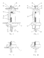
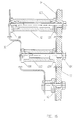
- FIG. 8 shows a further embodiment variant of the connecting device according to the invention 10, with the lower end 12 corresponding here the upper end 18 of the connecting device 10 of FIG. 1 is formed is, i.e. according to the RSF mother element from Profil.
- the upper end 18 of the one-piece connecting device 10 shown in FIG. 8 is, however, designed here as a blind rivet sleeve 70.
- the connection device 10 has a tightening mandrel 72 with shaft part 74 and head part 76 and predetermined breaking point 78.
- the lower area of the shaft part 74 is here provided with a knurled cross 80.
- the purpose of this training is that Generate shape features that slip when grasping a puller avoid. These shape features 80 can also have any other shape have that serves the stated purpose.
- the rivet sleeve 70 extends radially to the axial direction 31 the connecting device 10 extends over the first shoulder 82, the transition taking place via a second ring shoulder 84, the Diameter is larger than the outer diameter of the blind rivet sleeve 70, however smaller than the outer diameter of the ring shoulder 82.
- the connecting device 10 of FIG. 8 is first in a first Sheet metal part 14 used, the training in the region of the lower end 12 of the connecting device 10 in Fig. 9 of the training in the corresponding lower end 12 of the connecting device 10 of FIG. 1 equivalent.
- the second component 30 is also pre-punched here and, as on the left 9, provided with a conical collar 90 which extends in the direction away from the first component 14.
- the conical Collar 90 delimits a hole 92 with a diameter slightly larger than the outer diameter of the ring shoulder 84, but smaller than the outer diameter the ring shoulder 82.
- the predetermined breaking point 78 in the FIG. 9 embodiment is above of the threaded cylinder 28 is so that the rest of the mandrel the introduction a screw from below in the threaded cylinder 28 is not prevented.
- Fig. 10 shows a modified design of the lower end 12 of the Connection device 10 of Fig. 8.
- the lower end is namely here corresponding to the lower end 12 of the connecting device 10 of the 4 and 5
- the Fig. 10 shows the training before attachment on the first component 14, and
- FIG. 11 shows the position after the attachment shows on the first component 14.
- Fig. 12 shows an embodiment similar to Fig. 9, but of another Modification of the connection device 10.
- 12 could form one end of a shock absorber in the configuration of FIG screwed to component 14 using the threaded cylinder 28 be, while the threaded cylinder 102 for attaching a Brake line is used.
- FIG. 13 shows a further embodiment of a connecting device according to the invention 10, the already in the area of their lower end 12
- SBF element here - as is also shown in the Fig. 4 embodiment - is hollow with a threaded cylinder 28.
- FIG. 14 shows a possible attachment of the lower end 12 in one Cup-like first component 14.
- the upper end 18 of the connecting device 10 according to FIG. 14 is then glued to a second component 30.
- the two components 14 and 30 are then in contact with one another welded the positions 46 and 48.
- a third component 60 is then by means of a screw bolt 64 on which the components 14 and 30 existing assembly part screwed, the threaded part of the bolt 64 in the threaded cylinder 28 of the connecting device 10 is screwed. If necessary, here on the gluing can be dispensed with with the second component 30.
- FIG. 15 shows an embodiment which is very similar to the embodiment according to FIG. 7 is.
- the connecting device 10 is made in three parts. It consists at the end 12 of an RND element 12A from Profil, on End 18 from an RSF or SBF element 18A (in the case of the SBF element realized as a nut instead of a bolt element) and in between a spacer tube 112.
- the connection between the spacer tube 112 and element 12A at the lower end 12 and element 18A at upper end 18 can be done, for example, by welding.
- the thread the screw 64 engages in the threaded cylinder in the element 18A End 18 of the connecting device 10.
- Fig. 15 shows how connectors 10 different lengths generated by using spacer tubes of different lengths can be, in the lowest embodiment of the connecting device 10 no spacer tube is used at all.
- the connection between the two elements 12A, 18A and the spacer tube 112 can also be done differently.
- the Elements and the spacer tube attached to each other by gluing become. In some cases, this is certainly safe enough, because with the Tightening screw 64 stresses all joints in compression become.
- FIG. 16 is similar to that of FIG. 15, only here the spacer tube 112 in a cylindrical recess 116 of the element 12A pressed in at the end 12 of the connecting device 10 (possibly glued in), whereby a secure connection between the spacer tube 112 and the element is guaranteed.
- a corresponding connection would be finally also possible with the element at the end 18.
- the connection between the element at the end 18 and the spacer tube 112 can also in FIG. 16 Execution are welded.
- the connecting device is designed in two parts, wherein the lower end of the connector 10 through the end 12 of the Spacer tube 112 is formed and this in a pot-like depression 115 is received in the first component 14 and pressed in there, glued or can be welded.
- the connection between the spacer tube 112 and the element at the other end 18 of the connecting device 10 takes place as described in connection with FIGS. 15 and 16.
- the spacer tube 112 is an integral part of the element 18A, which is connected to the component 30 by forming technology.
- connection 18 is a three-part embodiment of the connecting device 10 before.
- two identical joining elements 12A, 18A in the form of RND nut elements from Profil used, with a spacer tube 112 is placed between the three-piece connector 10 manufacture.
- the elements 12A, 18A each have a cylindrical part 122 which is in a respective End of the spacer tube is pressed.
- the connections between the individual elements 12A, 18A and the spacer tube 112 can according to Be chosen at will, i.e. for example with a fit as a press fit, with Bonding, with welded connection or with crimped connection.
- Fig. 19 shows an embodiment similar to Fig. 18, only this is here Spacer tube 112 with cylindrical recesses 123 on its two Provide ends so that it is midway between the two elements is made thicker than in the embodiment according to FIG. 18. This increases the stability even further.
- connection device 10 This consists of an element 18A, which is designed as an RND element and form-fitting with the second Component 30 is connected.
- the second part of the connecting device 10 consists of a spacer tube 112 with cylindrical ring flanges 117 at both ends, the shape-fitting in the respective pot-like depressions 115 sit.
- the connection between the ends of the spacer tube 112 and the respective wells can be done at will, for example as a fit, as a press fit, or by means of an adhesive or a weld.
- Fig. 21 shows an embodiment according to the previous one Fig. 19, but with the two elements in the respective ends of the spacer tube 112 are pressed and these extending in the axial direction Has ribs or grooves 119 that the anti-rotation serve. There can also be a radial crimp connection between the elements and the spacer tube.
- FIG. 22 again shows an alternative, three-part design of a connecting device, here using two circular elements 12A, 18A, each having a flange 130 with a first diameter and a cylindrical part 132 with a smaller diameter than have the flange 130.
- the cylindrical part 132 which on its, the Flange 130 facing end face of a chamfer 134 is by a corresponding hole 136 or 138 is used in component 14 or 30.
- the arrangement is such that the two flanges 130 of the two Elements on opposite sides of the first and second component 14 and 30 lie, the ends 140 of the two elements are mutually facing.
- the front end 140 of the element 18A is conical Provide depression 141, which as an insertion aid for the tip a bolt.
- This type of insertion aid is special important if the inner diameter of the spacer tube 112 is significantly larger than the outer diameter of the bolt, as such Difference in diameter the risk of tilting the bolt in hides, who, with such an insertion aid, may have a corresponding one Formation of the free end of the bolt, for example with a conical Great, can be overcome.
- One more way, to overcome this risk of canting, which is the introduction of the bolt difficult or even prevented and possibly even damage the Thread could lead, is in connection with FIGS. 25A to D explained later. Both the conical insertion aid and the corresponding one Centering sleeve according to FIGS. 25A to D can be used with all others Embodiments of the invention are applied where the danger of canting exists.
- a spacer tube 112 is located between the two components 14, 30 a circumferential ring nose 142 on both ends.
- the top Element has a threaded cylinder 28, the lower element is cylindrical Bore 28A, the diameter of which is slightly larger than the outside diameter of the threaded cylinder 28.
- the arrangement is by Pressing pressed together. During this pressing they displace Ring lugs 142 material of the two components 14, 30 so that the displaced Material molded into respective ring grooves 144 of the elements 12A, 18A , creating a positive connection between the two Components 14 and 30 and the respective element 12A and 18A.
- the chamfers 134 make it easier to slip the respective elements into the Spacer tube 112.
- the cylindrical region 132 has a diameter which is slightly larger than the inner diameter of the spacer tube 112, so that a press fit is created here.
- Fig. 23 shows in principle the same arrangement as Fig. 22, but it shows that the connecting device here in angled areas of the respective Sheet metal parts 14 and 30 can be introduced.
- FIG. 24 shows a one-piece connecting device 10 similar to FIG. 4, however, the two ends of the connecting device against each other are offset. Such an implementation can sometimes be separate Installation cases help when there are special space restrictions consist. It is also possible to use the connecting device of FIG. 24 to equip two threaded cylinders 28, 102, for example the Threaded cylinder 28 at the lower end of the connecting device in Fig. 24 is used for attaching a third component 60 during the threaded cylinder 102 at the top of the connector for the Attachment of an additional part, for example a brake line attachment can be exploited.
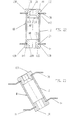
- FIGS. 25A to D show a possible method for the preparation of a compound according to the invention.
- 25A first shows a first sheet metal part 14 in a tool 149 a centering mandrel 150.
- the sheet metal part 14 has a U-shaped cross section Depression, in the bottom region of a first hollow element corresponding to the central element 12A of FIG. 18 is attached.
- the structure consisting of the sheet metal part 14 with the elements 12A is placed over the centering mandrel 150.
- the two lateral, horizontal Areas 14A and 14B sit on respective welding electrodes 152 or 154.
- FIG. 25B shows the structure of FIG. 25A, but with the spacer tube 112 is now placed over the centering sleeve and possibly on the cylindrical Projection 158 of element 12A can be pressed provided an interference fit is provided.
- an adhesive connection could be used or there is a connection with play.
- the spacer tube 112 could also be used to attach element 12A with this by one of the methods mentioned above, or with this be welded, or be integrally formed with this.
- the sheet metal part 14 there is a second sheet metal part 30, which with is provided with a nut member 18A corresponding to Fig. 18, wherein the element 18A is already riveted to the sheet metal part 30.
- the assembly part consisting of the nut element 18A and the sheet metal part 30 is now using the centering mandrel 150 according to FIG. 25C centered over the sheet metal part 14 and element 12A with spacer tube 112.
- the cylindrical protrusion 160 of the nut member 18A may be shown in FIG the free end of the spacer tube is pressed or glued or let in with play.
- the two sheet metal parts are made by means of two further welding electrodes 162, 164 welded.
- 25D then shows the finished construction after removal from the Tool 149 and after attaching a component 60 by means of a bolt 64.
- the centering sleeve 156 prevents the pin 64 from tilting when it is inserted.
- the element 18A could only be connected to the spacer tube and then riveted to the sheet metal part.
- the connection device consisting of the element 12A, the spacer tube 112, the Centering sleeve 156 and element 18A could also be prefabricated as a unit are then riveted to sheet metal part 18 or 30 and then are riveted to the other sheet metal part 30 or 18, and namely before or after its welded connection to the sheet metal part 18 or 30th
- the components are preferably sheet metal parts, but can also be extruded parts be or consist of other materials, for example Plastic.
Landscapes
- Engineering & Computer Science (AREA)
- General Engineering & Computer Science (AREA)
- Mechanical Engineering (AREA)
- Connection Of Plates (AREA)
- Insertion Pins And Rivets (AREA)
- Mutual Connection Of Rods And Tubes (AREA)
Description
- sie ermöglichen es, das erste und das zweite Bauteil (Blechteile oder Formteile aus anderen Materialien) mit geringen Toleranzen bezüglich der Lage und des Abstands der Formteile zueinander zu positionieren und bilden daher eine Art Lehre beim Zusammenbau der entsprechenden Bauteile;
- sie dienen als Mutter- oder Bolzenelement zum Anschrauben weiterer Bauteile mit hohen Betriebslasten;
- sie dienen der Absicherung der Winkligkeit und - falls erforderlich - der Ausdruck- und Verdrehsicherung bei der Montage;
- sie nehmen Betriebslasten, Scherung, Druckmomente jeweils statisch und dynamisch auf;
- auch bei der mehrteiligen Ausführung stellt der Zusammenhalt der Verbindungseinrichtung kein Problem dar, da die Verschraubung so vorgenommen werden kann, daß alle Elemente der Verbindungseinrichtung gegeneinander abgestützt sind.
- Fig. 1
- eine teilweise geschnittene Ansicht einer ersten Ausführungsvariante der erfindungsgemäßen Verbindungseinrichtung bei der Anwendung mit zwei, aus Blech bestehenden Bauteilen,
- Fig. 2
- die gleiche Ausführung wie Fig. 1, jedoch während der Verbindung der zwei Bauteile aneinander,
- Fig. 3
- die fertiggestellte Verbindung zwischen den zwei Bauteilen der Fig. 1 und 2,
- Fig. 4
- eine teilweise geschnittene Längsansicht einer zweiten erfindungsgemäßen Ausführung einer Verbindungseinrichtung,
- Fig. 5
- eine teilweise in Längsrichtung geschnittene Ansicht der Verbindungseinrichtung der Fig. 4 bei der Anwendung mit zwei, aus Blech bestehenden Bauteilen,
- Fig. 6
- eine Darstellung ähnlich dem unteren Teil der Fig. 5 bei einer Ausführung, bei der das erste Bauteil aus zwei aneinander gelegten Blechformteilen besteht,
- Fig. 7
- eine teilweise geschnittene Darstellung ähnlich der Fig. 5, jedoch für drei verschiedene Längen der erfindungsgemäßen Verbindungseinrichtung gemäß Fig. 4, wobei gleichzeitig das Anschrauben eines dritten Bauteils dargestellt wird,
- Fig. 8
- eine teilweise in Längsrichtung geschnittene Ansicht einer bevorzugten, erfindungsgemäßen Ausführung einer Verbindungseinrichtung mit einer Blindniethülse und einem Blindnietdorn,
- Fig. 9
- eine Darstellung ähnlich der Fig. 8, jedoch nach dem Einsetzen der erfindungsgemäßen Verbindungseinrichtung zwischen zwei, aus Blech bestehenden Bauteilen, wobei auf der linken Seite der Fig. 9 die Situation vor dem Anziehen der Blindnietverbindung und auf der rechten Seite die Situation nach dem Anziehen der Blindnietverbindung gezeigt ist,
- Fig. 10
- eine Darstellung des unteren Teils einer erfindungsgemäßen Verbindungseinrichtung ähnlich der Fig. 8, jedoch in einer etwas abgewandelten Ausbildung,
- Fig. 11
- den unteren Teil der Verbindungseinrichtung der Fig. 10 nach Einbringung in ein Blechformteil,
- Fig. 12
- eine etwas abgewandelte Ausführungsform der Verbindungseinrichtung der Fig. 8 in einer Darstellung entsprechend der Fig. 9,
- Fig. 13
- eine teilweise in Längsrichtung geschnittene Ansicht einer weiteren erfindungsgemäßen Ausführungsform einer Verbindungseinrichtung, welche die bevorzugte Ausführungsform darstellt,
- Fig. 14
- eine schematische Darstellung der Verbindungseinrichtung der Fig. 13 in zwei Bauteile eingebaut,
- Fig. 15-21
- Darstellungen ähnlich der Fig. 7, jedoch von abgewandelten Ausführungsformen der erfindungsgemäßen Verbindungseinrichtung,
- Fig. 22
- eine in Längsrichtung geschnittene Darstellung einer dreiteiligen erfindungsgemäßen Verbindungseinrichtung nach dem Einsetzen in zwei Bauteile,
- Fig. 23
- eine Darstellung ähnlich der Fig. 22, jedoch in einer geneigten Lage der Verbindungseinrichtung, und
- Fig. 24
- eine in Längsrichtung geschnittene Darstellung einer weiteren erfindungsgemäßen Ausführung einer Verbindungseinrichtung,
- Fig. 25A bis 25D
- verschiedene Herstellungsschritte bei dem Einbau einer erfindungsgemäßen Verbindungseinrichtung.
Claims (37)
- Verbindungseinrichtung (10), welche an ihrem einen Ende (12) über eine umformtechnisch herstellbare Verbindung (11), vorzugsweise eine Nietverbindung, an einem ersten Bauteil (14) befestigbar ist und einen Aufnahmebereich (28) aufweist, der zur Aufnahme eines Bolzens (64), einer Mutter oder eines anderen Elements, beispielsweise ein Bajonettteil oder eine Welle, ausgelegt ist, dadurch gekennzeichnet, daß die Verbindungseinrichtung in einem dem erstgenannten Ende (12) beabstandeten Bereich (18) zur reibschlüssigen oder umformtechnischen Anbringung an oder in ein zweites Bauteil (30) ausgelegt ist, wobei nach Fertigstellung einer Verbindung mit dem ersten Bauteil (14) und Anbringung des zweiten Bauteils (30) der Aufnahmebereich (28) die Anbringung eines weiteren Bauteils (60) ermöglicht.
- Verbindungseinrichtung (10) nach Anspruch 1, dadurch gekennzeichnet, daß der beabstandete Bereich am dem erstgenannten Ende (12) entgegengesetzten Ende (18) der Verbindungseinrichtung vorgesehen ist.
- Verbindungseinrichtung (10) nach Anspruch 1 oder 2, dadurch gekennzeichnet, daß der beabstandete Bereich (18) als Blindniethülse (70) ausgelegt ist.
- Verbindungseinrichtung (10) nach einem der vorhergehenden Ansprüche, dadurch gekennzeichnet, daß der beabstandete Bereich (18) für die umformtechnische Anbringung an ein zweites Bauteil (30) oder an einen weiteren Bereich des erstgenannten Bauteils (14) ausgelegt ist.
- Verbindungseinrichtung (10) nach einem der vorhergehenden Ansprüche, dadurch gekennzeichnet, daß sie einteilig ausgeführt ist.
- Verbindungseinrichtung (10) nach einem der vorhergehenden Ansprüche 1 bis 4, dadurch gekennzeichnet, daß sie mehrteilig (12A, 18A; 12A, 112, 18A) ausgeführt ist.
- Verbindungseinrichtung (10) nach Anspruch 6, dadurch gekennzeichnet, daß sie aus einem ersten Verbindungselement (12A) besteht das im Kopfbereich an das erstgenannte Bauteil (14) befestigbar ist und in oder auf ein stabförmiges Teil (112) führt und ggf. mit diesem verklebt, verschweißt oder über eine Quetschverbindung oder über eine andere Verbindung befestigt ist, wobei das stabförmige Teil (112) an seinem dem Kopfteil des Verbindungselementes (12A) entgegengesetzten Ende entweder an das zweite Bauteil (30) unmittelbar oder über ein weiteres Verbindungselement anbringbar ist, wobei im letzteren Fall das stabförmige Teil ggf. mit dem weiteren Verbindungselement (18A) verklebt, verschweißt oder vorzugsweise über eine form- und/oder kraftschlüssige Verbindung, beispielsweise eine Quetschverbindung, befestigt ist, wobei vorzugsweise eines (18A) der beiden Verbindungselemente (12A, 18A) ein Gewindeteil (28)(Innen- oder Außengewinde) und das andere (12A) eine Durchgangsbohrung aufweist.
- Verbindungseinrichtung (10) nach einem der vorhergehenden Ansprüche, dadurch gekennzeichnet, daß sie bzw. ein etwaiges stabförmiges Teil (112) als Distanzrohr ausgebildet ist.
- Verbindungseinrichtung (10) nach Anspruch 8, dadurch gekennzeichnet, daß das Distanzrohr mit einem Innengewinde ausgestattet ist das vorzugsweise benachbart zu einem der Enden der Verbindungseinrichtung angeordnet ist.
- Verbindungseinrichtung (10) nach einem der vorhergehenden Ansprüche, dadurch gekennzeichnet, das die beiden Enden der Verbindungseinrichtung gegeneinander versetzt angeordnet sind (Fig. 24), bspw. durch die Anwendung eines gekröpften stabförmigen Teils oder Distanzrohres.
- Verbindungseinrichtung (10) nach einem der vorhergehenden Ansprüche, dadurch gekennzeichnet, daß sie ein Innengewinde (28) oder Außengewinde zur Anbringung eines dritten Bauteils (60) mittels eines Bolzens (64) bzw. einer Mutter aufweist.
- Verbindungseinrichtung (10) nach einem der vorhergehenden Ansprüche, dadurch gekennzeichnet, daß die umformtechnisch herstellbare Verbindung (11) zur Anwendung mit einem vorgelochten Bauteil (14; 30) ausgelegt ist, beispielsweise unter Anwendung einer Verbindungseinrichtung mit Nietmerkmalen nach Art der RND-, RSN-, RSF-, RSK-, RSU-, HI- oder UM-Mutterelemente oder unter Anwendung einer Verbindungseinrichtung mit Formmerkmalen nach Art der EBF-, SBK- oder SBF-Bolzenelemente der Firma Profil Verbindungstechnik GmbH & Co. KG.
- Verbindungseinrichtung (10) nach einem der vorhergehenden Ansprüche 1 bis 11, dadurch gekennzeichnet, daß die umformtechnisch herstellbare Verbindung (11) zur Anwendung mit einem nicht-vorgelochten Bauteil (14, 30) ausgelegt ist, beispielsweise unter Anwendung einer Verbindungseinrichtung mit integriertem Vorlochen unter Anwendung einer Verbindungseinrichtung mit Formmerkmalen nach Art der RSK- oder RSU-Mutterelemente der Firma Profil Verbindungstechnik GmbH & Co. KG oder unter Anwendung einer Verbindungseinrichtung mit selbststanzenden Merkmalen, beispielsweise nach Art der UM-, HI-, RSF-Mutterelemente, oder EBF-(in selbststanzender Ausführung) oder SBK- oder SBF-Bolzenelementen der Firma Profil Verbindungstechnik GmbH & Co. KG.
- Verbindungseinrichtung (10) nach einem der vorhergehenden Ansprüche, dadurch gekennzeichnet, daß das erste Bauteil (14) und/oder das zweite Bauteil (30) mit topfartigen Vertiefungen (115) im Bereich der Anbringungsstelle der Verbindungseinrichtung (10) versehen sind.
- Verbindungseinrichtung (10) nach Anspruch 6 und einem oder mehreren der weiteren, vorhergehenden Ansprüche, dadurch gekennzeichnet, daß ein Mutterelement (12A) mit Niet- oder Stanzund Nietmerkmalen (22) zur Herstellung der umformtechnischen Verbindung (11) zum ersten Bauteil (14) zur Anwendung gelangt und das Mutterelement entweder wie üblich ein Gewinde (28) aufweist oder anstatt eines Gewindes mit einer Durchgangsbohrung versehen ist.
- Verbindungseinrichtung nach Anspruch 6 und einem oder mehreren der vorhergehenden Ansprüche, dadurch gekennzeichnet, daß bei Anwendung eines Bolzenelementes zur Herstellung der umformtechnischen Verbindung zum ersten Bauteil der Schaftteil des Bolzenelements entweder hohl ausgeführt ist oder eine massive Ausführung aufweist und mit getrenntem Distanzrohr und ggf. Mutter auf der dem zweiten Bauteil zugewandten Seite des ersten Bauteils ergänzt wird, wobei bei Anwendung eines Bolzenelements mit hohlem Schaftteil das Außengewinde des Schaftteils in ein Innengewinde des Distanzrohres einschraubbar sein kann und die Anbringung des dritten Bauteils über eine durch das erste Bauteil, das hohle Schaftteil und das Distanzrohr durchgeführte Schraube erfolgt, die entweder in ein Gewinde im Distanzrohr an dessen, dem ersten Bauteil abgewandten Ende, oder in ein Gewinde in einem am ersten Bauteil abgewandten Ende des Distanzrohres angebrachten und umformtechnisch mit dem zweiten Bauteil verbundenen Element oder in eine Mutter an der dem ersten Bauteil abgewandten Seite des zweiten Bauteils einschraubbar ist und bei Anwendung eines Bolzenelementes mit massivem Schaftteil diese entweder in ein Innengewinde mit Distanzrohr einschraubbar ist, wobei die Anbringung eines dritten Bauteiles dann auf der dem ersten Bauteil abgewandten Seite des zweiten Bauteils über eine Schraube erfolgt, die in ein Innengewinde im Distanzrohr eingreift, oder durch das Distanzrohr und das zweite Bauteil hindurchragt und dort zur Anbringung eines dritten Bauteils mit einer getrennten, auf der dem ersten Bauteil abgewandten Seite des zweiten Bauteils angeordneten Mutter zusammenarbeitet.
- Verbindungseinrichtung nach Anspruch 8, dadurch gekennzeichnet, daß das Distanzrohr (112) an seinem Stirnende bzw. an beiden Stirnenden mit einer Nase oder mit mehreren Nasen versehen ist, die zum eingreifen in eine oder mehrere entsprechende Vertiefungen bei bei der dem Distanzrohr zugeordneten Verbindungsstelle am ersten und/oder zweiten Bauteil (14, 30) ausgelegt sind.
- Verbindungseinrichtung (10) nach Anspruch 3, dadurch gekennzeichnet, daß die Verbindungseinrichtung (10) mit einem Dorn (72) mit Sollbruchstelle (78) ausgestattet ist, dessen Kopf (76) bei Ausübung von Ziehkräften auf das Schaftteil (74) des Dorns (72) zur Verformung der Blindniethülse (70) ausgelegt ist, wobei der Kopfteil (76) des Dorns entweder zur Entfernung aus dem Bereich der Verbindungseinrichtung (10) nach Verformung der Blindniethülse (70) oder durch das Vorsehen von Formmerkmalen, wie beispielsweise eine Hinterschneidung im Schaftteil benachbart zum Kopf zum form- und/oder kraftschlüssigen Verbleib mit der Verbindungseinrichtung (10) ausgelegt ist.
- Verbindungseinrichtung (10) nach Anspruch 3 und 18, dadurch gekennzeichnet, daß die Blindniethülse (70) in eine im Bereich der dem ersten Bauteil (14) zugewandten Seite des zweiten Bauteils (30) angeordnete Schulter (82) übergeht.
- Verbindungseinrichtung (10) nach Anspruch 19, dadurch gekennzeichnet, daß eine zweite Schulter (84) zwischen der Blindniethülse (70) und der ersten Schulter (80) angeordnet ist und einen Durchmesser aufweist, der größer als der Außendurchmesser der Blindniethülse (70), jedoch kleiner als der Außendurchmesser der ersten Schulter (82) ist und eine Höhe aufweist, die vorzugsweise zumindest in etwa die Dicke des zweiten Bauteils (30) im Bereich der Niethülse entspricht.
- Verbindungseinrichtung (10) nach Anspruch 19 oder 20, dadurch gekennzeichnet, daß sie zur Anwendung mit einem vorgelochten zweiten Bauteil ausgelegt (30) ist, dessen Lochung mit einer zumindest im wesentlichen konusförmigen, auf der vom ersten Bauteil (14) abgewandten Seite des zweiten Bauteils (30) vorstehenden Kragens (90) versehen ist und die Blindniethülse (70) und der Dorn (72) der Verbindungseinrichtung ausgelegt sind, um beim Anziehen des Dorns (72) den Kragen (90) über die Blindniethülse (70) zumindest im wesentlichen flach zu pressen entsprechend dem Vorgehen bei der Durchführung des sogenannten Klemmlochnietverfahrens (EP 0 539 793) ausgelegt ist.
- Verbindungseinrichtung (10) nach einem der Ansprüche 3 und 18 bis 21, dadurch gekennzeichnet, daß in der Verbindungseinrichtung zwischen der Niethülse (70) und dem ersten Bauteil (14) ein Gewinde (28) zur Aufnahme einer von der der Niethülse abgewandten Seite des ersten Bauteils eingeführte Schraube vorgesehen ist und vorzugsweise einen Kerndurchmesser aufweist, der etwas größer ist als der Außendurchmesser des Schaftteils (74) des Dorns (72).
- Verbindungseinrichtung (10) nach einem der Ansprüche 3 und 18 bis 22, dadurch gekennzeichnet, daß das Schaftteil (74) des Dorns (72) mit Formmerkmalen versehen ist, um ein sicheres Angreifen von einem Ziehwerkzeug zu ermöglichen.
- Verbindungseinrichtung (10) nach einem oder mehreren der vorhergehenden Ansprüche, dadurch gekennzeichnet, daß die urnformfähigen Enden (12, 18) der Verbindungseinrichtung (10) zur Erzeugung einer mediendichten Verbindung mit dem ersten und/oder zweiten Bauteil (14, 30) ausgelegt sind, wobei ggf. wärmestabile Kleber zur Sicherstellung gasdichter Verbindungen zur Anwendung bei dem Einsetzen der Verbindungseinrichtung gelangen können.
- Verbindungseinrichtung (10) nach einem der vorhergehenden Ansprüche 1 bis 24, welche ein Innengewinde (28) zur Aufnahme eines Bolzens (64) und einen rohrförmigen Bereich (112) aufweist, wobei der Innendurchmesser des rohrförmigen Bereiches größer ist als der Außendurchmesser des Bolzens (64), dadurch gekennzeichnet, daß im rohrförmigen Bereich eine konusförmige Einführhilfe vor dem Gewinde oder eine Zentrierhülse vorgesehen ist.
- Kombination einer Verbindungseinrichtung (10) nach einem der vorhergehenden Ansprüche mit einem Bauteil (14) bzw. mit zwei oder drei Bauteilen (14, 30; 14, 30, 60), dadurch gekennzeichnet, daß die umformtechnisch herstellbare Verbindung (11) zur Anwendung mit einem vorgelochten Bauteil (14) ausgelegt ist, beispielsweise unter Anwendung einer Verbindungseinrichtung mit Nietmerkmalen nach Art der RND-, RSN-, RSF-, RSK-, RSU, HI- oder UM-Mutterelemente oder unter Anwendung einer Verbindungseinrichtung mit Formmerkmalen nach Art der EBF-, SBK- oder SBF-Bolzenelemente der Firma Profil Verbindungstechnik GmbH & Co. KG.
- Kombination nach Anspruch 26, dadurch gekennzeichnet, daß die umformtechnisch herstellbare Verbindung (11) zur Anwendung mit einem nicht-vorgelochten (14) Bauteil ausgelegt ist, beispielsweise unter Anwendung einer Verbindungseinrichtung (10) mit integriertem Vorlochen unter Anwendung einer Verbindungseinrichtung mit Formmerkmalen nach Art der RSK- oder RSU-Mutterelemente der Firma Profil Verbindungstechnik GmbH & Co. KG oder unter Anwendung einer Verbindungseinrichtung mit selbststanzenden Merkmalen, beispielsweise nach Art der UM-, HI-, RSF-Mutterelemente, oder EBF-(in selbststanzender Ausführung) oder SBK- oder SBF-Bolzenelementen der Firma Profil Verbindungstechnik GmbH & Co. KG.
- Kombination nach Anspruch 26 oder 27, gekennzeichnet durch einen Bolzen (64), dessen Kopfteil auf der dem zweiten Bauteil (30) abgewandten Seite des ersten Bauteils (14) angeordnet ist und dessen Schaftteil sich durch das erste Bauteil und in die Verbindungseinrichtung (10) erstreckt und in einem Gewinde (28) eingeschraubt ist, daß sich entweder zwischen dem ersten und zweiten Bauteil in der Verbindungseinrichtung (10) oder auf der dem ersten Bauteil (14) abgewandten Seite des zweiten Bauteils (30) befindet.
- Kombination nach Anspruch 26 oder 27, dadurch gekennzeichnet, daß die Verbindungseinrichtung einen Schaftteil aufweist, der durch das zweite Bauteil hindurch ragt und in ein Mutterelement auf der dem ersten Bauteil abgewandten Seite des zweiten Bauteils eingreift.
- Kombination nach Anspruch 26 oder 27, gekennzeichnet durch einen Bolzen (64), dessen Kopfteil auf der dem ersten Bauteil (14) abgewandten Seite des zweiten Bauteils (30) angeordnet ist und dessen Schaftteil sich durch das zweite Bauteil (30) und in die Verbindungseinrichtung (10) erstreckt und in einem Gewinde (28) eingeschraubt ist, daß sich entweder zwischen dem ersten und zweiten Bauteil (14, 30) in der Verbindungseinrichtung oder auf der dem zweiten Bauteil (30) abgewandten Seite des ersten Bauteils (14) befindet.
- Kombination nach Anspruch 26 oder 27, dadurch gekennzeichnet, daß die Verbindungseinrichtung einen Schaftteil aufweist, der durch das erste Bauteil hindurch ragt und in ein Mutterelement auf der dem zweiten Bauteil abgewandten Seite des ersten Bauteils eingreift.
- Verfahren zur Herstellung einer Verbindung zwischen einem ersten und einem zweiten Blechteil (14, 30) unter Anwendung der Verbindungseinrichtung (10) nach einem der vorhergehenden Ansprüche, gekennzeichnet durch die folgenden Schritte :a) Durchführung einer umformtechnische Verbindung (11) des erstgenannten Endes der Verbindungseinrichtung mit dem ersten Blechteil (14),b) Einführung des vom ersten Ende beabstandeten Bereiches (18) der Verbindungseinrichtung (10) durch ein Loch im zweiten Blechteil (30),c) Befestigung der Verbindungseinrichtung (10) mit dem zweiten Blechteil (30) im beabstandeten Bereich, undd) ggf. Herstellung einer anderweitigen Verbindung wie bspw. eine Schweißverbindung und/oder eine Verklebung zwischen den beiden Blechteilen an einer Stelle oder an mehreren Stellen entfernt von der Verbindungseinrichtung, wobei der Schritt d) entweder vor oder nach dem Schritt c) durchgeführt werden kann.
- Verfahren nach Anspruch 32, dadurch gekennzeichnet, daß der Schritt a) entweder das Vorlochen des ersten Blechteils (14) umfaßt oder unter Anwendung einer selbststanzenden Ausbildung am erstgenannten Ende (12) der Verbindungseinrichtung (10) durchgeführt wird.
- Verfahren nach Anspruch 32, dadurch gekennzeichnet, daß der Schritt c) die Durchführung einer Nietverbindung umfaßt.
- Verfahren nach Anspruch 34, dadurch gekennzeichnet, daß die Nietverbindung nach Art einer Blindnietverbindung unter Anwendung eines die Vernietung durchführenden Dorns (72) durchgeführt wird, wobei das Anziehen des Dorns zur Herstellung der Nietverbindung vor oder nach dem Schritt d) durchgeführt wird.
- Verfahren nach Anspruch 32, dadurch gekennzeichnet, daß es unter Anwendung einer Verbindungseinrichtung (11) bestehend aus zwei Elementen (12A, 18A) durchgeführt wird, wobei bei Schritt a) das erste Element (12A) an dem ersten Blechteil (14) angebracht wird, im Schritt b) das zweite Element (18A) in das zweite Blechteil (30) eingeführt wird und die Verbindung der beiden Elemente (12A, 18A) miteinander entweder durch die Einführung eines Bolzens durch das eine Element (12A, 18A) in das andere Element (18A, 12A) oder durch die Anbringung einer Mutter auf ein mit Gewinde versehenen Schaftteil des einen Elements erfolgt, wobei in diesem Fall das Schaftteil des einen Elements durch eine Bohrung des weiteren Elementes sich hindurch erstreckt, oder dadurch, daß eine Schraube durch beide Elemente hindurchgeführt wird und mit einer Mutter gesichert wird, wobei Bereiche des ersten und zweiten Elementes, die sich zwischen dem ersten und zweiten Blechteil befinden, ein Distanzrohr zwischen diesen beiden Bauteilen bilden.
- Verfahren nach Anspruch 32 unter Anwendung einer Verbindungseinrichtung (10), die aus drei Elementen (12A, 18A, 112) besteht, wobei zur Durchführung von Schritt a) das erste Element (12A) mit dem ersten Blechteil (14) umformtechnisch verbunden wird, zur Durchführung der Schritte b) und c) das zweite Element (18A) am zweiten Blechteil (30) befestigt wird, und in einem weiteren Schritt, der zu einem beliebigen Zeitpunkt vor dem Schritt c) durchführbar ist, das dritte Element (112) der Verbindungseinrichtung, das als Distanzteil ausgebildet ist, zwischen dem ersten und zweiten Element (12A, 18A) eingesetzt wird.
Applications Claiming Priority (3)
| Application Number | Priority Date | Filing Date | Title |
|---|---|---|---|
| DE19815407 | 1998-04-06 | ||
| DE19815407A DE19815407A1 (de) | 1998-04-06 | 1998-04-06 | Verbindungseinrichtung zum Verbinden zweier Bauteile, Kombination der Verbindungseinrichtung mit den beiden Bauteilen und Verfahren zur Herstellung einer Verbindung zwischen zwei Bauteilen |
| PCT/EP1999/002236 WO1999051886A1 (de) | 1998-04-06 | 1999-04-01 | Verbindungseinrichtung zum verbinden zweier bauteile, kombination der verbindungseinrichtung mit den beiden bauteilen und verfahren zur herstellung einer verbindung zwischen zwei bauteilen |
Publications (2)
| Publication Number | Publication Date |
|---|---|
| EP1068458A1 EP1068458A1 (de) | 2001-01-17 |
| EP1068458B1 true EP1068458B1 (de) | 2003-01-15 |
Family
ID=7863778
Family Applications (1)
| Application Number | Title | Priority Date | Filing Date |
|---|---|---|---|
| EP99919174A Expired - Lifetime EP1068458B1 (de) | 1998-04-06 | 1999-04-01 | Verbindungseinrichtung zum verbinden zweier bauteile, kombination der verbindungseinrichtung mit den beiden bauteilen und verfahren zur herstellung einer verbindung zwischen zwei bauteilen |
Country Status (10)
| Country | Link |
|---|---|
| US (4) | US7010845B2 (de) |
| EP (1) | EP1068458B1 (de) |
| JP (1) | JP2002510779A (de) |
| KR (1) | KR20010034756A (de) |
| AU (1) | AU3704199A (de) |
| BR (1) | BR9909470A (de) |
| CA (1) | CA2327407A1 (de) |
| DE (2) | DE19815407A1 (de) |
| ES (1) | ES2186352T3 (de) |
| WO (1) | WO1999051886A1 (de) |
Cited By (3)
| Publication number | Priority date | Publication date | Assignee | Title |
|---|---|---|---|---|
| DE102008053346A1 (de) | 2008-10-27 | 2010-04-29 | Profil Verbindungstechnik Gmbh & Co. Kg | Abstandselement für die Anbringung an einem Blechteil, Zusammenbauteil und Verfahren zu dessen Herstellung |
| DE102011104971A1 (de) | 2011-06-20 | 2012-12-20 | Profil Verbindungstechnik Gmbh & Co. Kg | Einteiliges Funktionselement in der Form eines hohlen Nietelements |
| EP3832147B1 (de) * | 2019-12-05 | 2024-12-11 | Profil Verbindungstechnik GmbH & Co. KG | Befestigungselement |
Families Citing this family (46)
| Publication number | Priority date | Publication date | Assignee | Title |
|---|---|---|---|---|
| DE19815407A1 (de) | 1998-04-06 | 1999-10-07 | Profil Verbindungstechnik Gmbh | Verbindungseinrichtung zum Verbinden zweier Bauteile, Kombination der Verbindungseinrichtung mit den beiden Bauteilen und Verfahren zur Herstellung einer Verbindung zwischen zwei Bauteilen |
| DE19958148A1 (de) * | 1999-12-03 | 2001-06-28 | Volkswagen Ag | Anordnung zur Befestigung eines Gegenstandes an einem Hohlkörper |
| US20010032017A1 (en) | 1999-12-30 | 2001-10-18 | Alfaro Arthur A. | Intervertebral implants |
| US20030120274A1 (en) | 2000-10-20 | 2003-06-26 | Morris John W. | Implant retaining device |
| US8186920B2 (en) * | 2001-07-19 | 2012-05-29 | Whitesell International Corporation | Clinch element and method and apparatus for attaching a clinch element to a panel |
| US6855167B2 (en) | 2001-12-05 | 2005-02-15 | Osteotech, Inc. | Spinal intervertebral implant, interconnections for such implant and processes for making |
| US20050111934A1 (en) | 2003-11-14 | 2005-05-26 | Ladouceur Harold A. | Self-riveting male fastener and panel assembly |
| WO2005072656A1 (en) | 2004-01-27 | 2005-08-11 | Osteotech, Inc. | Stabilized bone graft |
| DE102004037471B3 (de) * | 2004-07-30 | 2006-04-27 | Newfrey Llc, Newark | Stanznietverbindung und Verfahren zu ihrer Herstellung |
| DE102004052053B4 (de) * | 2004-10-26 | 2014-01-16 | Fastenrath Befestigungstechnik Gmbh | Verfahren zum Befestigen eines Bauteils in einer Baukomponente |
| RU2418206C2 (ru) * | 2006-01-05 | 2011-05-10 | Профиль-Фербиндунгстехник Гмбх Унд Ко. Кг | Крепежный элемент, узловая сборка, состоящая из крепежного элемента и детали из листового металла, а также способ закрепления крепежного элемента на детали из листового металла |
| DE102006003667A1 (de) * | 2006-01-26 | 2007-08-09 | Bayerische Motoren Werke Ag | Karosserie eines Fahrzeuges |
| DE102006021843A1 (de) * | 2006-05-10 | 2007-11-15 | Böllhoff Verbindungstechnik GmbH | Abstandsniet, Nietverbindung und Verfahren zu ihrer Herstellung |
| DE102006033608B3 (de) * | 2006-07-18 | 2008-02-21 | Edscha Cabrio-Dachsysteme Gmbh | Lagervorrichtung |
| US8449234B2 (en) * | 2007-01-16 | 2013-05-28 | Harry E. Taylor | Blind rivet |
| CA2677903A1 (en) | 2007-02-12 | 2008-08-21 | Osteotech, Inc. | Joint revision implant |
| DE102007019699B4 (de) | 2007-04-26 | 2024-07-25 | Dr. Ing. H.C. F. Porsche Aktiengesellschaft | Schraubverbindung |
| FR2924370B1 (fr) * | 2007-12-04 | 2010-04-09 | Bollhoff Otalu Sa | Procede de sertissage d'un insert dans un support a deux panneaux superposes et ecrou noye a sertir |
| DE102008011344A1 (de) * | 2008-02-27 | 2009-09-03 | Newfrey Llc, Newark | Verfahren zum Befestigen eines Bauteils und Befestigungselement zur Durchführung des Verfahrens |
| JP5094544B2 (ja) * | 2008-05-16 | 2012-12-12 | 株式会社神戸製鋼所 | バンパー構造体 |
| US8092115B1 (en) | 2008-07-14 | 2012-01-10 | Cisco Technology, Inc. | Entrapped nut |
| US8047753B2 (en) | 2008-07-22 | 2011-11-01 | The Boeing Company | Insulating washers |
| US7878747B2 (en) * | 2008-07-22 | 2011-02-01 | The Boeing Company | Insulating cover for fasteners used in high temperature environments |
| US8366150B2 (en) * | 2009-05-13 | 2013-02-05 | Ford Global Technologies | Reinforcement tube assembly |
| DE102009028466B4 (de) | 2009-08-12 | 2021-08-05 | Zf Friedrichshafen Ag | Verfahren zum Vernieten zweier Bauteile, insbesondere Deckscheibenelemente einer Torsionsschwingungsdämpferanordnung, in gegenseitigem Abstand zueinander |
| DE102010007218A1 (de) * | 2010-02-09 | 2011-08-11 | GM Global Technology Operations LLC, ( n. d. Ges. d. Staates Delaware ), Mich. | Befestigungseinrichtung für eine Kraftfahrzeugkarosserie |
| AT510633B1 (de) * | 2010-11-12 | 2013-03-15 | Man Truck & Bus Oesterreich Ag | Befestigungseinrichtung für anbauteile |
| JP4961063B1 (ja) * | 2011-01-24 | 2012-06-27 | 豊田鉄工株式会社 | ペダルアームの軸受部材、およびペダルアーム |
| US9428224B2 (en) * | 2013-06-28 | 2016-08-30 | GM Global Technology Operations LLC | Drainable section stabilizer sleeve |
| WO2015031118A1 (en) * | 2013-08-29 | 2015-03-05 | Eaton Corporation | Bearing pin upset method to retain high hardness pins |
| JP5897690B1 (ja) * | 2014-11-10 | 2016-03-30 | 株式会社オティックス | 軸受装置 |
| US20160169264A1 (en) * | 2014-12-10 | 2016-06-16 | Newfrey Llc | Cage stud assembly and related assembly methods |
| US10016936B2 (en) * | 2015-10-30 | 2018-07-10 | Dura Operating, Llc | Hybrid metal polymer interlock |
| DE102015014504A1 (de) * | 2015-11-10 | 2017-05-11 | GM Global Technology Operations LLC (n. d. Ges. d. Staates Delaware) | Strukturbauteil für eine Kraftfahrzeugkarosserie |
| DE102016121756B3 (de) * | 2016-11-14 | 2018-01-04 | Benteler Automobiltechnik Gmbh | Karosserieanbindung eines Achshilfsrahmens sowie Verfahren zur Herstellung der Karosserieanbindung |
| CN106907567B (zh) * | 2017-03-15 | 2023-09-22 | 宾科精密部件(中国)有限公司 | 一种型材强化连接结构件 |
| EP3634662A4 (de) * | 2017-05-09 | 2021-05-19 | Penn Engineering & Manufacturing Corp. | Befestigungselement und installationsverfahren für sehr dünne bleche |
| CN108180201B (zh) * | 2018-02-09 | 2024-04-12 | 湖北博士隆科技股份有限公司 | 空心型材拉铆铆钉 |
| US10953930B2 (en) * | 2019-03-26 | 2021-03-23 | Honda Motor Co., Ltd. | Damper housing assembly |
| DE102019117086A1 (de) * | 2019-06-25 | 2020-12-31 | Profil Verbindungstechnik Gmbh & Co. Kg | Befestigungseinheit |
| JP7205404B2 (ja) * | 2019-06-28 | 2023-01-17 | トヨタ自動車株式会社 | 車両構造 |
| DE102021106103A1 (de) * | 2021-03-12 | 2022-09-15 | Profil Verbindungstechnik Gmbh & Co. Kg | Funktionselement |
| US20230197422A1 (en) * | 2021-12-20 | 2023-06-22 | Applied Materials, Inc. | Fastening assembly for beam blocker in ion processing apparatus |
| EP4559702A4 (de) * | 2022-07-19 | 2025-10-29 | Nippon Steel Corp | Befestigungselement, klebeverbindung und verfahren zur herstellung einer klebeverbindung |
| KR102797844B1 (ko) * | 2022-11-02 | 2025-04-22 | 주식회사 성우하이텍 | 클린칭 타입 블라인드 하이브리드 체결 장치 |
| DE102022130756B3 (de) * | 2022-11-21 | 2023-12-28 | Audi Planung GmbH | Nietverbindung |
Family Cites Families (39)
| Publication number | Priority date | Publication date | Assignee | Title |
|---|---|---|---|---|
| US1386691A (en) * | 1919-11-26 | 1921-08-09 | Duchesne Ernest | Staybolt-fastening |
| US2562336A (en) * | 1945-10-01 | 1951-07-31 | Goodrich Co B F | Rivet |
| US2767877A (en) * | 1954-01-11 | 1956-10-23 | North American Aviation Inc | Rivet adapted to secure two sheets in spaced relationship |
| US3563183A (en) * | 1968-12-26 | 1971-02-16 | Howard B Rich | Pallet construction |
| US3614702A (en) * | 1969-09-08 | 1971-10-19 | Elmwood Sensors | Terminal-contact rivet construction and method of assembly thereof |
| US3829957A (en) | 1972-10-30 | 1974-08-20 | Multifastener Corp | Method of assembling a self-fastening nut and a panel |
| FR2256687A5 (en) * | 1973-12-27 | 1975-07-25 | Snecma | Fastener for composite honeycomb structures - transfers load to outer layer through tapered hollow spacer |
| FR2315444A1 (fr) * | 1975-06-23 | 1977-01-21 | Lequeux Christian | Palette metallique et procede d'assemblage d'une telle palette |
| DE2844384C2 (de) | 1978-10-12 | 1986-10-23 | Daimler-Benz Ag, 7000 Stuttgart | Masse-Anschlußstelle für lackierte Blechbauteile |
| JPS597048B2 (ja) | 1979-11-17 | 1984-02-16 | 有限会社新城製作所 | クリンチナツト及びその取付方法 |
| US4310272A (en) | 1980-01-18 | 1982-01-12 | Textron Inc. | Threaded fastener and structural joint attained therewith |
| US4831698A (en) * | 1983-03-28 | 1989-05-23 | Multifastener Corporation | Method of attaching a female element to a panel |
| US4633560A (en) * | 1980-02-02 | 1987-01-06 | Multifastener Corporation | Self-attaching fastener, die set |
| US4610072A (en) | 1983-12-21 | 1986-09-09 | Multifastener Corporation | Method of installing a fastener to a panel |
| DE3345617C1 (de) | 1983-12-16 | 1985-01-10 | Daimler-Benz Ag, 7000 Stuttgart | Anschweißmutter für eine Masseanschlußstelle an Blechbauteilen |
| DE3404118A1 (de) | 1984-02-07 | 1985-08-14 | Profil-Verbindungstechnik Gmbh & Co Kg, 6382 Friedrichsdorf | Verfahren und vorrichtung zum anbringen einer mutter an einem plattenfoermigen werkstueck |
| US5531552A (en) | 1984-08-03 | 1996-07-02 | Multifastener Corporation | Self-attaching nut and method of making same |
| DE3602389A1 (de) * | 1986-01-28 | 1987-07-30 | Gronendahl Franz Josef | Einnietbares befestigungselement |
| DE3704763C1 (en) * | 1987-02-16 | 1988-10-13 | Voit Willy Gmbh & Co | Connection between a bolt, which has a head, and a metal sheet |
| DE3815502A1 (de) * | 1988-05-06 | 1989-11-16 | Swf Auto Electric Gmbh | Wischblatt, insbesondere fuer scheibenwischanlagen an kraftfahrzeugen und verfahren zu seiner herstellung |
| FR2637027B1 (fr) * | 1988-09-23 | 1990-12-07 | Cibie Projecteurs | Dispositif de fixation a douille expansible d'une piece sur sa platine support |
| DE3835556C2 (de) | 1988-10-19 | 2000-05-18 | Rheinmetall W & M Gmbh | Geradzug-Verschlußsystem |
| US5190803A (en) * | 1988-11-25 | 1993-03-02 | Bayer Aktiengesellschaft | Structural shell with reinforcing ribs connected via perforations |
| DE4010598A1 (de) * | 1989-04-05 | 1990-10-11 | Honsel Werke Ag | Blech oder leiste mit einem eingepressten, selbstnietenden gewindestift |
| DE3927529C1 (de) * | 1989-08-21 | 1991-03-07 | A. Raymond Kg, 7850 Loerrach, De | |
| DE3936376C1 (de) * | 1989-11-02 | 1991-01-03 | Audi Ag, 8070 Ingolstadt, De | |
| US5056207A (en) * | 1990-01-16 | 1991-10-15 | Multifastener Corporation | Method of attaching a self-piercing and riveting fastener and improved die member |
| FI89439C (fi) | 1991-10-30 | 1993-09-27 | Salon Televisiotehdas Oy | Foerfarande foer att dekoda en audiosignal i vilken annan information aer infoerd med anvaendning av maskningseffekt |
| DE4410475A1 (de) * | 1994-03-25 | 1995-09-28 | Profil Verbindungstechnik Gmbh | Vernietbares Element, Zusammenbauteil mit einem vernietbaren Element sowie Nietmatrize und Verfahren zur Herstellung des Zusammenbauteils |
| US5528812A (en) * | 1991-10-31 | 1996-06-25 | Profil-Verbindungstechnik Gmbh & Co. Kg | Method of attaching a fastener to a plurality of panels |
| DE4211276C2 (de) | 1992-04-03 | 1997-08-28 | Profil Verbindungstechnik Gmbh | Haltevorrichtung zum Halten, Führen und Freigeben eines Fügeteils, wie z.B. einer Mutter |
| DE4228463C2 (de) * | 1992-08-27 | 2001-07-26 | Halfen Gmbh & Co Kg | Verfahren zur Herstellung einer Ankerschiene für die Bautechnik und Vorrichtung zur Durchführung des Verfahrens |
| US5314280A (en) * | 1993-07-06 | 1994-05-24 | Ford Motor Company | Settable height adjusting fastener |
| JPH0829392B2 (ja) | 1993-12-17 | 1996-03-27 | 有限会社新城製作所 | ピアスナットの製造装置 |
| DE4417279C2 (de) * | 1994-05-13 | 2000-07-06 | Brose Fahrzeugteile | Vorrichtung zum formschlüssigen Verbinden zumindest eines ersten drehbaren Bauteils und eines zweiten drehfesten Bauteils durch ein Verbindungsteil |
| DE19647831A1 (de) | 1996-11-19 | 1998-05-20 | Profil Verbindungstechnik Gmbh | Verfahren zur Anbringung eines Funktionselementes; Funktionselement, Zusammenbauteil, Matrize und Setzkopf |
| DE19530466A1 (de) | 1995-08-18 | 1997-02-20 | Profil Verbindungstechnik Gmbh | Hohlkörperelement, Matrize zur Anwendung mit dem Hohlkörperelement, Verfahren zur Anbringung des Hohlkörperelementes an ein plattenförmiges Bauteil und Zusammenbauteil |
| DE19535537A1 (de) * | 1995-09-25 | 1997-03-27 | Profil Verbindungstechnik Gmbh | Bolzenelement, Verfahren zum Einsetzen desselben, Zusammenbauteil und Nietmatrize |
| DE19815407A1 (de) | 1998-04-06 | 1999-10-07 | Profil Verbindungstechnik Gmbh | Verbindungseinrichtung zum Verbinden zweier Bauteile, Kombination der Verbindungseinrichtung mit den beiden Bauteilen und Verfahren zur Herstellung einer Verbindung zwischen zwei Bauteilen |
-
1998
- 1998-04-06 DE DE19815407A patent/DE19815407A1/de not_active Withdrawn
-
1999
- 1999-04-01 WO PCT/EP1999/002236 patent/WO1999051886A1/de not_active Ceased
- 1999-04-01 DE DE59904044T patent/DE59904044D1/de not_active Expired - Lifetime
- 1999-04-01 BR BR9909470-3A patent/BR9909470A/pt not_active IP Right Cessation
- 1999-04-01 CA CA002327407A patent/CA2327407A1/en not_active Abandoned
- 1999-04-01 KR KR1020007011149A patent/KR20010034756A/ko not_active Ceased
- 1999-04-01 ES ES99919174T patent/ES2186352T3/es not_active Expired - Lifetime
- 1999-04-01 JP JP2000542582A patent/JP2002510779A/ja active Pending
- 1999-04-01 EP EP99919174A patent/EP1068458B1/de not_active Expired - Lifetime
- 1999-04-01 AU AU37041/99A patent/AU3704199A/en not_active Abandoned
-
2003
- 2003-07-23 US US10/625,274 patent/US7010845B2/en not_active Expired - Lifetime
-
2005
- 2005-08-02 US US11/195,451 patent/US7334958B2/en not_active Expired - Fee Related
-
2007
- 2007-10-22 US US11/876,065 patent/US20080256780A1/en not_active Abandoned
-
2010
- 2010-06-01 US US12/791,784 patent/US20100303579A1/en not_active Abandoned
Cited By (6)
| Publication number | Priority date | Publication date | Assignee | Title |
|---|---|---|---|---|
| DE102008053346A1 (de) | 2008-10-27 | 2010-04-29 | Profil Verbindungstechnik Gmbh & Co. Kg | Abstandselement für die Anbringung an einem Blechteil, Zusammenbauteil und Verfahren zu dessen Herstellung |
| EP2187070A1 (de) | 2008-10-27 | 2010-05-19 | Profil Verbindungstechnik GmbH & Co. KG | Abstandselement zur Befestigung eines Metallblechteils, Komponentenanordnung und Verfahren zu dessen Herstellung |
| US8371783B2 (en) | 2008-10-27 | 2013-02-12 | Profil-Verbindungstechnik Gmbh & Co. Kg | Spacer element for the attachment of a sheet metal part, component assembly and method for its manufacture |
| US8591158B2 (en) | 2008-10-27 | 2013-11-26 | Profil Verbindungstechnik Gmbh & Co. Kg | Spacer element for the attachment of a sheet metal part, component assembly and method for its manufacture |
| DE102011104971A1 (de) | 2011-06-20 | 2012-12-20 | Profil Verbindungstechnik Gmbh & Co. Kg | Einteiliges Funktionselement in der Form eines hohlen Nietelements |
| EP3832147B1 (de) * | 2019-12-05 | 2024-12-11 | Profil Verbindungstechnik GmbH & Co. KG | Befestigungselement |
Also Published As
| Publication number | Publication date |
|---|---|
| CA2327407A1 (en) | 1999-10-14 |
| US20050265804A1 (en) | 2005-12-01 |
| EP1068458A1 (de) | 2001-01-17 |
| US20080256780A1 (en) | 2008-10-23 |
| ES2186352T3 (es) | 2003-05-01 |
| AU3704199A (en) | 1999-10-25 |
| US20100303579A1 (en) | 2010-12-02 |
| US20050097722A1 (en) | 2005-05-12 |
| KR20010034756A (ko) | 2001-04-25 |
| JP2002510779A (ja) | 2002-04-09 |
| US7334958B2 (en) | 2008-02-26 |
| DE59904044D1 (de) | 2003-02-20 |
| US7010845B2 (en) | 2006-03-14 |
| BR9909470A (pt) | 2000-12-19 |
| DE19815407A1 (de) | 1999-10-07 |
| WO1999051886A1 (de) | 1999-10-14 |
Similar Documents
| Publication | Publication Date | Title |
|---|---|---|
| EP1068458A1 (de) | Verbindungseinrichtung zum verbinden zweier bauteile, kombination der verbindungseinrichtung mit den beiden bauteilen und verfahren zur herstellung einer verbindung zwischen zwei bauteilen | |
| EP2082143B1 (de) | Kombination aus einer schraube, einer unterlegscheibe und einer hülse sowie verfahren zum herstellen einer solchen kombination | |
| EP2177776B1 (de) | Vorrichtung bestehend aus einem Befestigunselement und einem Blechteil sowie ein Verfahren zur Herstellung einer solchen Vorrichtung | |
| EP2486288B2 (de) | Verbindung zwischen zwei bauteilen aus verstärktem kunststoff und verfahren zu ihrer herstellung | |
| EP1852212B1 (de) | Verfahren zum Herstellung eines Gelenks, Gelenk sowie Gelenkbolzen | |
| EP0842733B1 (de) | Verfahren zur Anbringung eines Funktionselementes, Funktionselement, Zusammenbauteil und Matrize | |
| DE102008031121A1 (de) | Schweißnietverbindung | |
| EP0487890A1 (de) | bauteilverbindung, insbesondere Flanschverbindung | |
| DE102011001522B4 (de) | Verbindungselement zur Herstellung einer Verbindung zwischen wenigstens zwei sich überlappenden Bauteilen und Verfahren zur Herstellung dieser Verbindung | |
| EP2047125A1 (de) | Hülse | |
| DE10115420A1 (de) | Verfahren zur Herstellung von Hohlkörperelementen, Profil zur Anwendung in dem Verfahren, Hohlkörperelement, Zusammenbauteil und Matrize | |
| EP2484924A1 (de) | Fügeverbindung sowie Verfahren zur Ausbildung einer Fügeverbindung | |
| EP3568257B1 (de) | Bauteilverbund von mindestens zwei bauteilen und ein verfahren zur herstelllung eines form- und/oder kraftschlüssig gefügten bauteilverbundes | |
| WO2007065398A1 (de) | Verfahren zum anbringen eines funktionselementes an einem flachmaterial sowie verbindung zwischen einem funktionselement und einem flachmaterial | |
| WO2018037004A1 (de) | Verbindungselement zum herstellen einer verbindung zwischen einem hohlprofil und einem weiteren bauteil | |
| DE102005031916B4 (de) | Halbhohlstanzniet zum mechanischen Fügen und Verfahren zum Herstellen einer Fügeverbindung | |
| WO2012031671A1 (de) | Verfahren zum einbringen einer hülse, insbesondere einer gewindehülse in ein werkstück | |
| EP3054182A1 (de) | Verfahren zur herstellung einer fügeverbindung zwischen einem gelenkgehäuse und einem anbindungsbauteil, sowie verfahrensgemäss hergestelltes fahrwerkbauteil | |
| EP3832147B1 (de) | Befestigungselement | |
| EP3877105B1 (de) | Befestigungseinheit | |
| EP2082144A1 (de) | Kombination aus einer schraube und einer hülse sowie verfahren zum herstellen einer solchen kombination | |
| DE19950719B4 (de) | Arbeitsverfahren zur Herstellung einer Nietverbindung sowie Niet, Nietwerkzeug und Anwendung derselben | |
| DE102008023044B4 (de) | Verfahren zum Anbringen eines Füge- oder Funktionselementes an einem plastisch verformbaren Flachmaterial | |
| DE19949524C1 (de) | Zweiteiliger Niet | |
| EP4033113B1 (de) | Selbststanzendes funktionselement, zusammenbauteil und verfahren zur herstellung eines zusammenbauteils |
Legal Events
| Date | Code | Title | Description |
|---|---|---|---|
| PUAI | Public reference made under article 153(3) epc to a published international application that has entered the european phase |
Free format text: ORIGINAL CODE: 0009012 |
|
| 17P | Request for examination filed |
Effective date: 20001004 |
|
| AK | Designated contracting states |
Kind code of ref document: A1 Designated state(s): DE ES FR GB IT |
|
| 17Q | First examination report despatched |
Effective date: 20010831 |
|
| GRAG | Despatch of communication of intention to grant |
Free format text: ORIGINAL CODE: EPIDOS AGRA |
|
| GRAG | Despatch of communication of intention to grant |
Free format text: ORIGINAL CODE: EPIDOS AGRA |
|
| GRAH | Despatch of communication of intention to grant a patent |
Free format text: ORIGINAL CODE: EPIDOS IGRA |
|
| GRAH | Despatch of communication of intention to grant a patent |
Free format text: ORIGINAL CODE: EPIDOS IGRA |
|
| GRAA | (expected) grant |
Free format text: ORIGINAL CODE: 0009210 |
|
| AK | Designated contracting states |
Kind code of ref document: B1 Designated state(s): DE ES FR GB IT |
|
| REG | Reference to a national code |
Ref country code: GB Ref legal event code: FG4D Free format text: NOT ENGLISH |
|
| REF | Corresponds to: |
Ref document number: 59904044 Country of ref document: DE Date of ref document: 20030220 Kind code of ref document: P |
|
| GBT | Gb: translation of ep patent filed (gb section 77(6)(a)/1977) |
Effective date: 20030328 |
|
| REG | Reference to a national code |
Ref country code: ES Ref legal event code: FG2A Ref document number: 2186352 Country of ref document: ES Kind code of ref document: T3 |
|
| ET | Fr: translation filed | ||
| PLBE | No opposition filed within time limit |
Free format text: ORIGINAL CODE: 0009261 |
|
| STAA | Information on the status of an ep patent application or granted ep patent |
Free format text: STATUS: NO OPPOSITION FILED WITHIN TIME LIMIT |
|
| 26N | No opposition filed |
Effective date: 20031016 |
|
| REG | Reference to a national code |
Ref country code: GB Ref legal event code: 732E |
|
| REG | Reference to a national code |
Ref country code: GB Ref legal event code: 732E |
|
| REG | Reference to a national code |
Ref country code: FR Ref legal event code: TP Ref country code: FR Ref legal event code: CD Ref country code: FR Ref legal event code: CA |
|
| REG | Reference to a national code |
Ref country code: FR Ref legal event code: GC |
|
| REG | Reference to a national code |
Ref country code: FR Ref legal event code: GC |
|
| REG | Reference to a national code |
Ref country code: FR Ref legal event code: RG Effective date: 20150206 |
|
| REG | Reference to a national code |
Ref country code: FR Ref legal event code: PLFP Year of fee payment: 18 |
|
| REG | Reference to a national code |
Ref country code: FR Ref legal event code: PLFP Year of fee payment: 19 |
|
| REG | Reference to a national code |
Ref country code: FR Ref legal event code: PLFP Year of fee payment: 20 |
|
| PGFP | Annual fee paid to national office [announced via postgrant information from national office to epo] |
Ref country code: ES Payment date: 20180525 Year of fee payment: 20 |
|
| PGFP | Annual fee paid to national office [announced via postgrant information from national office to epo] |
Ref country code: IT Payment date: 20180423 Year of fee payment: 20 Ref country code: FR Payment date: 20180420 Year of fee payment: 20 |
|
| PGFP | Annual fee paid to national office [announced via postgrant information from national office to epo] |
Ref country code: DE Payment date: 20180628 Year of fee payment: 20 Ref country code: GB Payment date: 20180418 Year of fee payment: 20 |
|
| REG | Reference to a national code |
Ref country code: DE Ref legal event code: R071 Ref document number: 59904044 Country of ref document: DE |
|
| REG | Reference to a national code |
Ref country code: GB Ref legal event code: PE20 Expiry date: 20190331 |
|
| PG25 | Lapsed in a contracting state [announced via postgrant information from national office to epo] |
Ref country code: GB Free format text: LAPSE BECAUSE OF EXPIRATION OF PROTECTION Effective date: 20190331 |
|
| REG | Reference to a national code |
Ref country code: ES Ref legal event code: FD2A Effective date: 20200721 |
|
| PG25 | Lapsed in a contracting state [announced via postgrant information from national office to epo] |
Ref country code: ES Free format text: LAPSE BECAUSE OF EXPIRATION OF PROTECTION Effective date: 20190402 |