EP1068923B1 - Procédé pour obtenir une répartition d'intensité sur un faisceau laser de travail ainsi qu'un appareil pour celà - Google Patents
Procédé pour obtenir une répartition d'intensité sur un faisceau laser de travail ainsi qu'un appareil pour celà Download PDFInfo
- Publication number
- EP1068923B1 EP1068923B1 EP20000810552 EP00810552A EP1068923B1 EP 1068923 B1 EP1068923 B1 EP 1068923B1 EP 20000810552 EP20000810552 EP 20000810552 EP 00810552 A EP00810552 A EP 00810552A EP 1068923 B1 EP1068923 B1 EP 1068923B1
- Authority
- EP
- European Patent Office
- Prior art keywords
- beams
- profile
- power
- laser
- source
- Prior art date
- Legal status (The legal status is an assumption and is not a legal conclusion. Google has not performed a legal analysis and makes no representation as to the accuracy of the status listed.)
- Expired - Lifetime
Links
Images

Classifications
-
- B—PERFORMING OPERATIONS; TRANSPORTING
- B23—MACHINE TOOLS; METAL-WORKING NOT OTHERWISE PROVIDED FOR
- B23K—SOLDERING OR UNSOLDERING; WELDING; CLADDING OR PLATING BY SOLDERING OR WELDING; CUTTING BY APPLYING HEAT LOCALLY, e.g. FLAME CUTTING; WORKING BY LASER BEAM
- B23K26/00—Working by laser beam, e.g. welding, cutting or boring
- B23K26/02—Positioning or observing the workpiece, e.g. with respect to the point of impact; Aligning, aiming or focusing the laser beam
- B23K26/06—Shaping the laser beam, e.g. by masks or multi-focusing
- B23K26/0604—Shaping the laser beam, e.g. by masks or multi-focusing by a combination of beams
- B23K26/0613—Shaping the laser beam, e.g. by masks or multi-focusing by a combination of beams having a common axis
-
- B—PERFORMING OPERATIONS; TRANSPORTING
- B23—MACHINE TOOLS; METAL-WORKING NOT OTHERWISE PROVIDED FOR
- B23K—SOLDERING OR UNSOLDERING; WELDING; CLADDING OR PLATING BY SOLDERING OR WELDING; CUTTING BY APPLYING HEAT LOCALLY, e.g. FLAME CUTTING; WORKING BY LASER BEAM
- B23K26/00—Working by laser beam, e.g. welding, cutting or boring
- B23K26/02—Positioning or observing the workpiece, e.g. with respect to the point of impact; Aligning, aiming or focusing the laser beam
- B23K26/06—Shaping the laser beam, e.g. by masks or multi-focusing
- B23K26/0604—Shaping the laser beam, e.g. by masks or multi-focusing by a combination of beams
-
- B—PERFORMING OPERATIONS; TRANSPORTING
- B23—MACHINE TOOLS; METAL-WORKING NOT OTHERWISE PROVIDED FOR
- B23K—SOLDERING OR UNSOLDERING; WELDING; CLADDING OR PLATING BY SOLDERING OR WELDING; CUTTING BY APPLYING HEAT LOCALLY, e.g. FLAME CUTTING; WORKING BY LASER BEAM
- B23K26/00—Working by laser beam, e.g. welding, cutting or boring
- B23K26/02—Positioning or observing the workpiece, e.g. with respect to the point of impact; Aligning, aiming or focusing the laser beam
- B23K26/06—Shaping the laser beam, e.g. by masks or multi-focusing
- B23K26/067—Dividing the beam into multiple beams, e.g. multi-focusing
-
- C—CHEMISTRY; METALLURGY
- C21—METALLURGY OF IRON
- C21D—MODIFYING THE PHYSICAL STRUCTURE OF FERROUS METALS; GENERAL DEVICES FOR HEAT TREATMENT OF FERROUS OR NON-FERROUS METALS OR ALLOYS; MAKING METAL MALLEABLE, e.g. BY DECARBURISATION OR TEMPERING
- C21D1/00—General methods or devices for heat treatment, e.g. annealing, hardening, quenching or tempering
- C21D1/06—Surface hardening
- C21D1/09—Surface hardening by direct application of electrical or wave energy; by particle radiation
Definitions
- the invention relates to a method according to the preamble of patent claim 1 and a device according to the preamble of patent claim 10.
- the intensity distribution of a material processing laser beam on a tool surface has hitherto been adjusted with focusing lenses of different focal lengths.
- the imaging of laser beams can be described with the Gaussian ray theory. In simple terms, it can be said that the wider a collimated laser beam impinging on a focusing lens, the smaller its focus diameter and the shorter its focusing depth.
- the intensity distribution on a tool surface to be machined has thus far been adjusted by a suitable selection of a focusing lens with a corresponding preceding beam widening.
- mode apertures at the "right" place in the laser resonator By a suitable choice of so-called mode apertures at the "right" place in the laser resonator, the generated laser mode was also changed.
- a mode aperture with a small cross-section resulted in a fundamental mode, while mode apertures with a large aperture gave a broad multimode beam.
- the beam expander enlarges or reduces the beam diameter of the respective partial beam.
- a subsequent focused by a lens beam change in dependence of the beam expansion or reduction of its focus diameter and its depth of field.
- optical switching elements such as a Pockels cell (electro-optical effect), a Faraday rotator (magneto-optical effect) or acousto-optic modulators only the total radiated power could be changed.
- optical switching elements such as a Pockels cell (electro-optical effect), a Faraday rotator (magneto-optical effect) or acousto-optic modulators only the total radiated power could be changed.
- the relative intensity distribution over the focused beam cross section thus remained, apart from diffraction effects and spatial distortions.
- the EP 0 338 816 A2 a periodic Q-switch laser.
- the Q-switch pulses of a single source beam are split by means of partially transmissive mirror into three sub-beams. Each partial beam passes through an optical modulator for leveling the pulse heights. Subsequently, these three sub-beams with "set" pulse heights via deflecting mirrors and a focusing optics to three adjacent locations to increase the processing speed on a printing cylinder 1 out.
- the object of the invention is to provide a method and a device with which the waveform of an intensity distribution over the cross section of a laser beam (beam profile) at the processing location quickly, ie with switching times up to submicron, changeable.
- a change in the beam profile is not achievable only by damping the entire material processing beam; this would again result in the same beam profile except for diffraction effects and distortions.
- the linear factor a can additionally be varied.
- the object is achieved by using at least two partial beams with different intensity distribution over the beam cross section (beam profile), which are combined to form a working beam.
- This working beam is then directed to be processed focused on an object surface preferably.
- x and y are meant the coordinates of a plane, preferably over the beam cross-section and under t a time dependence.
- the combination of the two beams ⁇ l1 + l2 then gives a working beam with a different function f 3 (x, y, t) of the intensity distribution over the beam cross section. It can thereby "fast” control the "diameter" of the working beam. This results in a workpiece to be machined not only an adjustable intensity, but also an adjustable or specifiable depth of field profile.
- the invention is preferable to use wherever material erosions are required whose depth and width change spatially rapidly.
- a preferred field of application is the production of sieve cups on a gravure cylinder.
- a Reichenfelpfher ein using laser radiation is from the WO 96/34718 known.
- an intensity distribution was used, as can be achieved by focusing a single beam.
- the partial beams can be switched on and off at different times or partially switched on and off.
- This means that not only a fast intensity variation of the intensity distribution over the beam cross-section (beam profile) but also temporal variation is possible: ⁇ l1 + l2 + .... ⁇ f a1 (t) ⁇ f 1 (x, y, t) + f a2 (t) ⁇ f 2 (x, y, t) + ....
- This type of variation will be used wherever short-term warm-up effects (eg the formation of a plasma cloud) are important.
- Material removal is not mandatory for the application of the invention; a use can also be made in a Vietnamesematerialabtragenden laser marking as well as during material hardening.
- objects may be illuminated (e.g., modulated pumping of laser crystals or media). It can be used with pulsed and also with continuous laser beams.
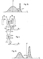
- the device according to the invention shown in FIG. 1 is used here, for example, for the production of screen cups on a gravure cylinder 1 .
- the device has a periodic Q-switch Nd-YAG laser 21 as a radiation source.
- the laser 21 emits a source beam 23 with an adjustable repetition frequency of up to 70 kHz.
- the repetition frequency of the periodic Q-switch laser 21 is generated by means of an acousto-optic modulator (not shown) arranged inside the laser resonator.
- the acousto-optic modulator within the laser resonator, the two power setting devices 7a and 7b , the positioning device 9 and the laser power supply, not shown, to the laser 21 are electrically connected via signal lines to a controller 25 having a memory controller 27 .
- the pulsed laser beam 23 emanating from the laser 21 is split into the two partial beams 3a and 3b with a power setting device designed as an acousto-optic modulator 7a .
- a power setting device designed as an acousto-optic modulator 7a .
- the partial beam 3b is guided to a further acousto-optical modulator 7b as a power setting device.
- a single partial beam 3b ' is continued by this modulator. That is, the power of the sub-beam 3b ' is attenuated with respect to the injected power of the sub-beam 3b as a function of the acoustic modulation stroke.
- the beam profiles of the two partial beams 3a and 3b ' are differently shaped when coupled into a respective radiation conductor 30a and 30b by its coupling optics 32a and 32b and its optical coupling-out system 29a and 29b , which radiates the decoupled beam in a collimated manner, specifically such that partial beam 3a a wide beam diameter and partial beam 3b ' receives a narrow beam diameter.
- the beam shaping can now take place through the radiation conductors (monomode fiber, multimode fiber, use with fibers with different doping profile) or through the refractive or diffractive optical systems 29 a and 29 b following the fiber end for decoupling, or through both.
- the partial beams 3a " and 3b" coupled out of the radiation conductors 30a and 30b with the optical systems 29a and 29b are collimated.
- the optical systems 29a and 29b are preferably formed such that the beam diameter of the sub-beam 3a "is significantly smaller than that of the sub-beam 3b" .
- Depending on the optical system 29a and 29b also have a different depth of focus of each partial beam in focus on the surface 19 is then obtained.
- the sub-beam 3b " is guided by a deflection mirror 31 through 90 ° onto a superposition mirror 33.
- the deflection mirror 31 and the superposition mirror 33 form the merging device 13 for the two sub-beams 3a" and 3b " "physical” union using polarizing beamsplitters or partially transmissive mirrors, which would also be possible within the scope of the method of the invention but would result in a 50% power loss.
- the mirror 33 has a central hole, through which the partial beam 3a " can pass unhindered.
- the partial beam 3b " is surrounded by the mirror surface surrounding the hole deflected by 90 ° reflecting. Both partial beams 3a " and 3b” are now brought together coaxially to the material processing beam 17 , which is focused with the focusing device 15 on the surface 19 of the gravure cylinder 1 .
- the narrow partial beam 3a " according to the intensity distribution curve 35 with a relatively large focus diameter d 2 and the partial beam 3b" shown in dashed lines in FIG. 2 are imaged on the surface 19 according to the dot-dashed intensity distribution curve 37 with a small focus diameter d 1 .
- the edge of the focus point is defined by a drop in intensity to 1 / e th part of the maximum value.
- the partial beam 3a "with the large focus diameter d 2 requires the greatest possible power, and when the partial beams 3a" and 3b "are combined , the partial beam 3a" should be completely transmitted with the high power.
- the gravure cylinder 1 per laser pulse wells with a variable diameter of 10 .mu.m to 180 .mu.m with a variable hole depth up to 50 .mu.m at an aspect ratio (hole depth to hole diameter) of up to 2 produced.
- Suitable means that the power of the sub-beam 3a is lowered and at the same time that of the sub-beam 3b is increased in such a way that, in spite of a decreasing well diameter, an equal well depth is always obtained.
- the control of the two modulators 7a and 7b for this purpose is determined experimentally. The resulting well diameter is measured. The experimental values are stored in the memory 25 . To prepare the Rasternäpfchen on the gravure cylinder 1 the required dot data are stored in the memory 25 of the control device.
- the control device 27 controls now depending on the material used of the gravure cylinder 1, the pump power of the laser 21 and its located in the resonator acousto-optic modulator. The control of this modulator determines the repetition frequency of the pulses of the laser beam 23 and thus gives a clear assignment for the control of the other two acousto-optic modulators 7a and 7b and the positioning of the gravure cylinder 1 with the positioning device 9.
- the acoustic wave in each modulator is in megahertz range.
- a switching of the modulators 7a and 7b is thus extremely fast in relation to the repetition frequency of the laser (maximum 70 kHz) and thus a setting of the corresponding power data of each partial beam for each laser pulse is possible.
- the power of the sub-beam 3a depends on the power output by the laser 21 and the power component coupled into the sub-beam 3b . This overcoupled power component can then be controlled by the acousto-optic modulator 7b controlled by the controller 27 .
- a different superposition curve for the intensity profile at the focal point on the gravure cylinder surface is obtained in comparison with the representation in FIG . If the beam profile of the partial beams to be superimposed is to be changed, the two partial beams or else only one in the beam profile shaping device 5a or 5b must be modified. This can be done by a variation of the optical system (lens system 29a and 29b ). Also, other radiation conductors z. B. be used with a different core diameter or a different doping profile.
- the radiation conductors 30a and 30b can be dispensed with, which results in a simpler beam guidance only through the lens systems.
- the radiation conductors 30a and 30b were used here in order to be able to keep vibrations from the positioning device 9 from the optical system.
- a different beam combination can be selected in which a small deflecting mirror for the" vertical "partial beam now running straight in the middle of the now" straight “partial beam. thin "partial beam is used.
- a plane-parallel, inclined plate can also be used.
- the plate is provided on both sides with an antireflective coating and carries only in the middle of one of its surfaces, which faces the rotogravure cylinder to be processed, a reflective coating.
- the diameter of the reflective coating is adapted to the diameter of the thin beam.
- the plate is set up at 45 ° to the axis of the "big” jet. This beam penetrates the plate with losses caused by the reflective coating and a small lateral offset caused by the plate thickness and tilt.
- the "small" beam is perpendicular to the axis of the "large” beam and is reflected by the reflective coating, which preferably has the beam axis of the large beam in its center, parallel to the beam axis in the large beam (superimposed).
- the partial beams of two separate Q-switch lasers can be generated, the internal Q-switch modulators would then have to be synchronized by the controller 27 .
- FIG. 2 shows a coaxial combination of two partial beams, for example.
- a plurality of partial beams can also be combined to form a single material processing beam having a predetermined intensity profile. It is then possible to achieve a further increase in intensity in the beam center or a beam broadening with an increase in intensity in the beam edge regions.
- Other beams can be generated by the use of further optical switching elements, such as by the acousto-optic modulators described above.
- a coaxial (centric) combination of partial beams a non-coaxial as well as a combination of non-parallel partial beams can be made ( FIGS.
- Non-parallel partial beams are obtained, for example, by a slight tilting of the deflection mirror 31 .
- a so-called. Galvanometer mirror can be used by a electric drive is adjustable. Such an arrangement will be chosen if wells [holes or blind holes (eg sieve cups)] with a non-circular cross-section are to be produced.
- well separated spatially separated partial beams depending on the number of partial beams, a plurality of depressions with different aspect ratios can be produced.
- engraving patterns with small intermediate points between the large cells can then be used to increase the print density and to improve the color flow behavior.
- the optical axis of the above-mentioned partial beams is always perpendicular to the surface to be processed 19 ; However, it can also be softening from the vertical, in which case the optical axes of individual partial beams can have different angles.
- the power adjusters 7a and 7b may also (additionally, if desired) make a different, fast power profiling time. It can thus follow a high initial pulse, a low power curve.
- the acousto-optical modulator 7b would be completely opened for the beam and then partially closed within the pulse after a predetermined time. Also the beginning of the pulse could be reduced. In the merged state of the partial beams one obtains a location-dependent temporal variation of the intensity profile in this way.
- the deflection mirror 31 can also be designed as a so-called adaptive mirror. With the mirror alone, the beam profile of the partial beam 3b can then be changed quickly.
- an electro-optical modulator for beam splitting or damping
- an electro-optical modulator for beam splitting or damping
- an electro-optical modulator for beam splitting or damping
- a magneto-optical modulator for magneto-optical modulator
- these two last switching elements work in contrast to the acousto-optic switching element with polarized radiation.
- the merging device 13 can also be moved with the focusing device 15 , which is easily possible due to the laser power supply via the radiation conductors 30a and 30b .
- the laser pulse frequency for generating the above-mentioned pressure cups can be selectively increased, for example, by using not just one pulsed laser but several.
- the individual, spaced apart pulses of the laser devices can then be targeted with an analog arrangement as shown in the US Pat. No. 5,856,648 is described, connected and merged into a beam with a given now increased pulse rate.
- FIG. 4 shows an arrangement with two lasers 50a and 50b .
- the two lasers 50a and 50b emit pulsed laser source beams 51a and 51b whose pulses are offset from each other in time.
- the two source beams 51a and 51b are deflected in such a way that they impinge on two acousto-optic modulators 53a and 53b arranged one behind the other at a predetermined angle.
- the predetermined angle corresponds to the deflection angle of the first order generated at each switched on modulator 53a or 53b. If the two modulators 53a and 53b are not switched on, then the beams 51a and 51b penetrate the two modulators 53a and 53b in the unaltered direction and proceed as beams 55a and 55b separately.
- a modulator 53a or 53b If a modulator 53a or 53b is connected, then a deflection takes place and, corresponding to the height of the modulation stroke , a corresponding energy coupling into the deflected beam 57a or 57b , which lies between the two beams 55a and 55b .
- the two modulators 53a and 53b synchronized with the laser pulses are arranged such that the respectively deflected beam of modulator 53a and that of 53b have one and the same optical axis. Both beams 57a and 57b are deflected by a small deflection mirror 59 and coupled into a radiation conductor fiber 60 . Beam components of the two beams 51a and 51b are thus guided in the radiation conductor 60 .
- the beams 55a and 55b which have only a part of the radiation energy of the beams 51a and 51b are guided on two further modulators 61a and 61b, with which the just described analog radiation association of the beams is carried 55a and 55b to a beam 63 ,
- the beam 63 also becomes a radiation conductor 65 coupled.
- the radiation guided in the radiation conductors 60 and 65 can continue to be used as beam 3b " and 3a" analogously to a structure as shown in FIG .
Landscapes
- Physics & Mathematics (AREA)
- Optics & Photonics (AREA)
- Engineering & Computer Science (AREA)
- Plasma & Fusion (AREA)
- Mechanical Engineering (AREA)
- Laser Beam Processing (AREA)
- Manufacture Or Reproduction Of Printing Formes (AREA)
- Lasers (AREA)
Claims (18)
- Procédé pour produire une répartition d'intensité spécifiable sur une surface d'objet (19) ou dans un objet (1), ce pour quoi on part d'un faisceau de source (23 ; 51a; 51b) avec un profil de faisceau de source d'un laser (21 ; 50a ; 50b), à partir du faisceau de source (23 ; 51a ; 51b) est formé au moins un premier et un second faisceau partiel (3a, 3a", 3b, 3b', 3b"), la puissance de chaque faisceau partiel (3a, 3a", 3b, 3b', 3b") est modifiable avec des durées de commutation spécifiables descendant à des valeurs inférieures aux microsecondes, caractérisé en ce qu'à partir du profil de faisceau de source au moins un premier profil de faisceau pour le premier faisceau partiel (3a") et un second profil de faisceau se distinguant du premier profil de faisceau pour le second faisceau partiel (3b") sont produits, ensuite au moins le premier et le second faisceaux partiels (3a", 3b") sont superposés et réunis en un unique faisceau de travail (17) et pointés sur la surface d'objet (19) ou dans l'objet (1), le faisceau de travail (17) recevant un profil de faisceau de travail avec la répartition d'intensité spécifiable et ainsi le profil de faisceau de travail étant modifié avec des durées de commutation descendant à des valeurs inférieures aux microsecondes, et des profils de faisceau distincts peuvant être produits.
- Procédé selon la revendication 1, caractérisé en ce que à partir du faisceau de source (23) sont formés un premier et un second faisceau partiel (3a, 3a", 3b, 3b', 3b") avec respectivement une première et une seconde puissance partielle spécifiables de façon commandée lors de la division.
- Procédé selon la revendication 1 ou 2, caractérisé en ce que les rayonnements de tous les faisceaux partiels (3a, 3a", 3b, 3b', 3b") sont émis en coïncidence temporelle depuis la source de rayonnement concernée (21) et réunis en un seul faisceau de travail (17) avec superposition au moins partielle dans l'espace, le faisceau réuni (17) est dirigé de façon focalisée sur la surface de l'objet (19) ou dans l'objet (1), et l'emplacement dans ou sur l'objet (19, 1) est modifié constamment.
- Procédé selon la revendication 3, caractérisé en ce que la superposition des faisceaux est réalisée géométriquement.
- Procédé selon l'une quelconque des revendications 1 à 4, caractérisé en ce que l'évolution temporelle de puissance du rayonnement d'au moins un faisceau partiel (3a, 3a", 3b, 3b', 3b") est modifiée dans le temps de façon commandée avec des durées de commutation descendant à des valeurs inférieures aux microsecondes, et la puissance de chaque faisceau partiel (3a, 3a", 3b, 3b', 3b") est modifiée par un pilotage électrique correspondant d'un dispositif de commutation optique, tel qu'un élément (7a, 7b) électro-optique, acousto-optique ou magnéto-optique, et une scission du faisceau en les au moins deux faisceaux partiels (3a, 3a", 3b, 3b', 3b") est réalisée de préférence par au moins un de ces éléments.
- Procédé selon l'une quelconque des revendications 1 à 5, caractérisé en ce que le profil de faisceau de chaque faisceau partiel (3a, 3a", 3b, 3b', 3b") est formé avant leur réunion en un profil donné, afin d'obtenir avec une focalisation successive le profil de faisceau donné qui se distingue fondamentalement de celui de chaque faisceau individuel focalisé et que l'on peut faire varier avec des durées de commutation descendant à des valeurs inférieures aux microsecondes sans déplacement mécanique des composants optiques.
- Procédé selon l'une quelconque des revendications 1 à 6, caractérisé en ce que les profils de faisceaux distincts peuvent être produits par une mise en forme de faisceau avec un guide de rayonnement (30a, 30b) en tant que fibres monomodales, fibres multimodales, fibres avec un profil de concentration variable du dopant ou avec un système optique (29a, 29b) réfractif ou diffractif rattaché à l'extrémité de fibre pour le découplage de rayonnement, ou par les deux.
- Procédé selon l'une quelconque des revendications 1 à 7, caractérisé en ce qu'un premier faisceau (23) d'un laser pulsé (21) est scindé au moyen d'un premier modulateur acousto-optique (7a) en un premier et un second faisceaux partiels (3a, 3b) avec des puissances partielles réglables par le premier modulateur (7a), le premier faisceau partiel (3a) est formé sur un profil de faisceau donné avec une répartition d'intensité donnée sur sa section transversale, le second faisceau partiel (3b) est modulé en puissance au moyen d'un second modulateur acousto-optique (7b) et est formé sur un profil de faisceau également donné avec une répartition d'intensité donnée qui peut se distinguer de celle/celles du premier faisceau partiel (3a"), les deux faisceaux partiels (3a'', 3b") sont réunis pour former un faisceau de traitement de matière (17) et sont focalisés sur la surface de matière (19), l'emplacement de focalisation de rayonnement est modifié chaque fois après un nombre prédéterminé d'impulsions du laser (21), la modification de l'emplacement et l'intensité du premier et du second faisceaux partiels (3a, 3a", 3b, 3b', 3b") étant modifiées de façon commandée au moyen des deux modulateurs (7a, 7b) de telle sorte qu'une série de cuvettes de différents rapports d'aspect soient formées sur la surface de matière (19) afin qu'une surface (19) traitée de cette manière, dans la mesure où elle fait partie d'un cylindre, soit utilisable en tant que cylindre d'héliogravure (1).
- Procédé selon l'une quelconque des revendications 1 à 8, caractérisé en ce que les faisceaux partiels (3a", 3b") sont regroupés pour la réunification en tant que faisceau partiel coaxial ou non coaxial ou s'étendant non parallèlement.
- Dispositif pour produire une répartition d'intensité spécifiable sur une surface d'objet (19) ou dans un objet (1), ce pour quoi on part d'un faisceau de source (23 ; 51a ; 51b) avec un profil de faisceau de source d'un laser (21 ; 50a ; 50b) ; avec au moins une unité de division de faisceau (7a, 7b) avec laquelle à partir du faisceau de source (23 ; 51a ; 51b) peut être produit au moins un premier et un second faisceaux partiels (3a, 3a", 3b, 3b', 3b"), avec au moins un dispositif de réglage de puissance (7a, 7b) commutant à une vitesse descendant à des valeurs inférieures aux microsecondes pour les faisceaux partiels (3a, 3a", 3b, 3b"), avec une unité de réunion (13) pour réunir les faisceaux partiels (3a", 3b"), avec un dispositif de positionnement (9) et de préférence un dispositif de focalisation (15), caractérisé par au moins une unité de mise en forme de profil de faisceau (5a, 5b), avec laquelle le profil de faisceau de source est modifiable en au moins un premier profil de faisceau pour le premier faisceau partiel (3a") et un second profil de faisceau se distinguant du premier profil de faisceau pour le second faisceau partiel (3b"), un unique faisceau de travail (17) pouvant être formé, avec l'unité de réunion (13) à partir des deux faisceaux partiels (3a", 3b") avec une superposition des deux profils de faisceau, avec un profil de faisceau de travail modifiable avec des durées de commutation descendant à des valeurs inférieures aux microsecondes avec la répartition d'intensité spécifiable et le faisceau de travail (17) pouvant être guidé avec le dispositif de positionnement (9), de préférence focalisé avec le dispositif de focalisation (15) sur ou dans l'objet (19, 1).
- Dispositif selon la revendication 10, caractérisé en ce qu'avec le dispositif diviseur de faisceau (7a, 7b) simultanément à une répartition de faisceau du faisceau de source (23) en deux faisceaux partiels (3a, 3a", 3b, 3b', 3b"), une répartition de puissance en une première puissance partielle d'un premier faisceau partiel (3a, 3a") et en une seconde puissance partielle d'un second faisceau partiel (3b, 3b', 3b") peut également être entreprise de façon commandée avec des temps de commande descendant à des valeurs inférieures aux microsecondes, chaque faisceau partiel (3a, 3a", 3b, 3b', 3b") ayant alors la première ou la seconde répartition de puissance (35, 37).
- Dispositif selon la revendication 10 ou 11, caractérisé par un laser pulsé en tant que source de rayonnement (21) pour la production d'au moins un faisceau de source (23), un diviseur de faisceau agissant également en tant que dispositif de réglage de puissance (7a) et avec lequel le faisceau de source (23) peut être réparti dans les deux faisceaux partiels (3a, 3b) de telle sorte que chaque faisceau partiel (3a, 3b) aie une puissance donnée par impulsion laser, et un autre dispositif de réglage de puissance (7b) en vue du réglage de puissance du rayonnement d'un des deux faisceaux partiels (3b).
- Dispositif selon la revendication 12, caractérisé en ce que le laser (21) est un laser « Q-switch » pulsé périodiquement.
- Dispositif selon la revendication 12 ou 13, caractérisé en ce que le diviseur de faisceau agissant également en tant que dispositif de réglage de puissance (7a) est conçu de telle sorte que chaque faisceau partiel (3a, 3b) aie une puissance spécifiable par impulsion laser.
- Dispositif selon l'une quelconque des revendications 12 à 14, caractérisé en ce que le diviseur de faisceau (7a) est conçu comme modulateur acousto-optique ou électro-optique.
- Dispositif selon l'une quelconque des revendications 12 à 15, caractérisé en ce que l'autre dispositif de réglage de puissance (7b) est un autre modulateur acousto-optique ou électro-optique.
- Dispositif selon l'une quelconque des revendications 10 à 16, caractérisé en ce que pour les profils de faisceau distincts il est prévu au moins un guide de rayonnement (30a, 30b) qui est constitué en tant que fibre monomodale, fibre multimodale, fibre avec un profil de concentration variable du dopant, ou au moins un système optique (29a, 29b) réfractif ou diffractif rattaché à l'extrémité de fibre pour le découplage de rayonnement ou les deux.
- Dispositif selon l'une quelconque des revendications 10 à 17, caractérisé par un dispositif de commande (17) comportant une mémoire (25) dans laquelle peuvent être mémorisées des informations de trame pour les points d'image d'une trame d'héliogravure, un cylindre d'héliogravure (1) dont la surface (19) est la surface de l'objet à traiter, une connexion électrique du dispositif de commande (17) avec chaque dispositif de réglage de puissance (7a, 7b) pour commander en puissance les faisceaux partiels (3a, 3b) pour chaque impulsion de rayonnement, afin d'obtenir par point de trame à générer sur le cylindre d'héliogravure un profil d'intensité spécifiable sur la section du faisceau et/ou dans le temps du faisceau de travail (17) sur la surface de l'objet à traiter (19) en tant que surface d'objet pour un enlèvement de matière avec un rapport d'aspect spécifiable .
Priority Applications (1)
| Application Number | Priority Date | Filing Date | Title |
|---|---|---|---|
| EP20000810552 EP1068923B1 (fr) | 1999-07-12 | 2000-06-23 | Procédé pour obtenir une répartition d'intensité sur un faisceau laser de travail ainsi qu'un appareil pour celà |
Applications Claiming Priority (4)
| Application Number | Priority Date | Filing Date | Title |
|---|---|---|---|
| EP99810623A EP1072350A1 (fr) | 1999-07-12 | 1999-07-12 | Procédé et dispositif pour effectuer une distribution de l'intensité dans rayon laser |
| EP98810623 | 1999-07-12 | ||
| EP99810623 | 1999-07-12 | ||
| EP20000810552 EP1068923B1 (fr) | 1999-07-12 | 2000-06-23 | Procédé pour obtenir une répartition d'intensité sur un faisceau laser de travail ainsi qu'un appareil pour celà |
Publications (3)
| Publication Number | Publication Date |
|---|---|
| EP1068923A2 EP1068923A2 (fr) | 2001-01-17 |
| EP1068923A3 EP1068923A3 (fr) | 2003-02-12 |
| EP1068923B1 true EP1068923B1 (fr) | 2007-10-17 |
Family
ID=26073926
Family Applications (1)
| Application Number | Title | Priority Date | Filing Date |
|---|---|---|---|
| EP20000810552 Expired - Lifetime EP1068923B1 (fr) | 1999-07-12 | 2000-06-23 | Procédé pour obtenir une répartition d'intensité sur un faisceau laser de travail ainsi qu'un appareil pour celà |
Country Status (1)
| Country | Link |
|---|---|
| EP (1) | EP1068923B1 (fr) |
Cited By (3)
| Publication number | Priority date | Publication date | Assignee | Title |
|---|---|---|---|---|
| DE102017203669B3 (de) | 2017-03-07 | 2018-06-28 | Robert Bosch Gmbh | Verfahren und Vorrichtung zur Formung kohärenter Strahlung |
| DE102017203655A1 (de) | 2017-03-07 | 2018-09-13 | Robert Bosch Gmbh | Verfahren und Vorrichtung zur Formung von Strahlung für die Laserbearbeitung |
| DE102017203671A1 (de) | 2017-03-07 | 2018-09-13 | Robert Bosch Gmbh | Verfahren zur Strahlformung bei einem Laserbearbeitungsprozess und Laseranordnung |
Families Citing this family (6)
| Publication number | Priority date | Publication date | Assignee | Title |
|---|---|---|---|---|
| DE10116093C1 (de) * | 2001-03-30 | 2002-06-13 | Schepers Gmbh & Co Kg | Verfahren zum Betreiben einer Lasergravureinrichtung |
| DE502006001300D1 (de) | 2005-05-03 | 2008-09-25 | Merck Patent Gmbh | Verwendung von lasergravierten Druckformen |
| DE102007032903A1 (de) | 2007-07-14 | 2009-01-15 | Schepers Gmbh + Co. Kg | Verfahren zum Betreiben einer Lasergravureinrichtung |
| DE102014110285A1 (de) * | 2014-07-22 | 2016-01-28 | Thyssenkrupp Ag | Einrichtung und Verfahren zum Strukturieren einer Walze durch Laserabtrag |
| DE102017200170A1 (de) * | 2017-01-09 | 2018-07-12 | Robert Bosch Gmbh | Vorrichtung und Verfahren zur Formung eines Laserstrahls durch einen programmierbaren Strahlformer |
| CN112605525A (zh) * | 2020-11-17 | 2021-04-06 | 武汉锐科光纤激光技术股份有限公司 | 一种激光输出光缆 |
Family Cites Families (8)
| Publication number | Priority date | Publication date | Assignee | Title |
|---|---|---|---|---|
| WO1988006504A1 (fr) * | 1987-02-24 | 1988-09-07 | Nippon Steel Corporation | Procede et installation de finition mate de cylindres a l'aide d'un laser pulse |
| US4937424A (en) * | 1987-07-20 | 1990-06-26 | Mitsubishi Denki Kabushiki Kaisha | Laser machining apparatus |
| JPH0651913B2 (ja) * | 1988-04-22 | 1994-07-06 | 川崎製鉄株式会社 | 圧延用ロールの表面加工方法及びその装置並びに該方法により製造されるプレス加工用金属薄板とその製造方法 |
| US4958900A (en) * | 1989-03-27 | 1990-09-25 | General Electric Company | Multi-fiber holder for output coupler and methods using same |
| DE4212390A1 (de) * | 1992-04-13 | 1993-10-14 | Baasel Carl Lasertech | Strahlführungssystem für mehrere Laserstrahlen |
| CH689917A5 (de) * | 1995-05-03 | 2000-01-31 | Daetwyler Ag | Verfahren und Vorrichtung zur Herstellung von Rasternäpfchen in der Oberfläche eines Tiefdruckzylinders. |
| DE19544502C1 (de) * | 1995-11-29 | 1997-05-15 | Baasel Scheel Lasergraphics Gm | Lasergravuranlage |
| DE19609199A1 (de) * | 1996-03-09 | 1997-09-11 | Vetter & Co Apotheker | Verfahren zur Bearbeitung von Werkstücken aus festen Materialien sowie Vorrichtung zur Durchführung des Verfahrens |
-
2000
- 2000-06-23 EP EP20000810552 patent/EP1068923B1/fr not_active Expired - Lifetime
Cited By (5)
| Publication number | Priority date | Publication date | Assignee | Title |
|---|---|---|---|---|
| DE102017203669B3 (de) | 2017-03-07 | 2018-06-28 | Robert Bosch Gmbh | Verfahren und Vorrichtung zur Formung kohärenter Strahlung |
| WO2018162357A1 (fr) | 2017-03-07 | 2018-09-13 | Robert Bosch Gmbh | Procédé et dispositif de formation d'un rayonnement cohérent |
| DE102017203655A1 (de) | 2017-03-07 | 2018-09-13 | Robert Bosch Gmbh | Verfahren und Vorrichtung zur Formung von Strahlung für die Laserbearbeitung |
| DE102017203671A1 (de) | 2017-03-07 | 2018-09-13 | Robert Bosch Gmbh | Verfahren zur Strahlformung bei einem Laserbearbeitungsprozess und Laseranordnung |
| DE102017203655B4 (de) | 2017-03-07 | 2019-08-22 | Robert Bosch Gmbh | Verfahren und Vorrichtung zur Formung von Strahlung für die Laserbearbeitung |
Also Published As
| Publication number | Publication date |
|---|---|
| EP1068923A3 (fr) | 2003-02-12 |
| EP1068923A2 (fr) | 2001-01-17 |
Similar Documents
| Publication | Publication Date | Title |
|---|---|---|
| EP1072350A1 (fr) | Procédé et dispositif pour effectuer une distribution de l'intensité dans rayon laser | |
| DE19544502C1 (de) | Lasergravuranlage | |
| DE3850330T2 (de) | Gerät zur mattveredelung einer rolle mittels impulslaser. | |
| EP2113332B1 (fr) | Procédé et dispositif pour l'usinage et/ou assemblage de pièces avec des lasers de puissance et pilote et au moins un élément optique diffractant | |
| DE10193737B4 (de) | Laserbearbeitungsvorrichtung | |
| DE2719275C2 (fr) | ||
| DE69314791T2 (de) | Druckkopf | |
| EP1896893B1 (fr) | Dispositif de mise en forme de rayon | |
| EP1465747B1 (fr) | Dispositif d'usinage par laser | |
| DE102012207220A1 (de) | Verfahren zur Bearbeitung eines Werkstücks mit Laserstrahlung | |
| WO2001060560A1 (fr) | Procede pour usiner des pieces au moyen de plusieurs rayons laser | |
| EP2976176A1 (fr) | Procédé et système pour former une structuration sur des surfaces de pièces au moyen d'un faisceau laser | |
| DE60006586T2 (de) | Laserstrahlvorrichtung zum zielen und verfahren zum schneiden oder markieren eines werkstücks | |
| EP4557003A2 (fr) | Dispositif d'usinage laser | |
| EP1068923B1 (fr) | Procédé pour obtenir une répartition d'intensité sur un faisceau laser de travail ainsi qu'un appareil pour celà | |
| DE60102597T2 (de) | Laser mit hoher spitzenleistung und dessen anwendung zur erzeugung von licht im extrem-uv-bereich | |
| DE102020107760A1 (de) | Laserbearbeitungsvorrichtung und Verfahren zur Laserbearbeitung eines Werkstücks | |
| DE102020102077A1 (de) | Laserbearbeitungsvorrichtung und Verfahren zur Laserbearbeitung eines Werkstücks | |
| DE4341553C1 (de) | Vorrichtung zum Homogenisieren der Lichtverteilung eines Laserstrahles | |
| WO2022135909A1 (fr) | Dispositif pour influer sur le faisceau d'un faisceau laser | |
| DE102018106579A1 (de) | Verfahren zur Bearbeitung eines Werkstücks mittels Bestrahlung mit Laserstrahlung sowie Vorrichtung hierzu | |
| EP1308235A1 (fr) | Méthode et dispositif de commande de l'énergie d'un faisceau laser | |
| EP0692741B1 (fr) | Dispositif de fabrication pour écran sérigraphique | |
| EP4204179A1 (fr) | Procédé pour usiner un matériau | |
| WO2022122238A1 (fr) | Usinage au laser d'une pièce à usiner partiellement transparente à l'aide d'un faisceau laser pratiquement non diffractant |
Legal Events
| Date | Code | Title | Description |
|---|---|---|---|
| PUAI | Public reference made under article 153(3) epc to a published international application that has entered the european phase |
Free format text: ORIGINAL CODE: 0009012 |
|
| AK | Designated contracting states |
Kind code of ref document: A2 Designated state(s): AT BE CH CY DE DK ES FI FR GB GR IE IT LI LU MC NL PT SE |
|
| AX | Request for extension of the european patent |
Free format text: AL;LT;LV;MK;RO;SI |
|
| GBC | Gb: translation of claims filed (gb section 78(7)/1977) | ||
| EL | Fr: translation of claims filed | ||
| RAP1 | Party data changed (applicant data changed or rights of an application transferred) |
Owner name: MDC MAX DAETWYLER AG BLEIENBACH |
|
| REG | Reference to a national code |
Ref country code: ES Ref legal event code: BA2A Ref document number: 2156842 Country of ref document: ES Kind code of ref document: T1 |
|
| PUAL | Search report despatched |
Free format text: ORIGINAL CODE: 0009013 |
|
| AK | Designated contracting states |
Designated state(s): AT BE CH CY DE DK ES FI FR GB GR IE IT LI LU MC NL PT SE |
|
| AX | Request for extension of the european patent |
Extension state: AL LT LV MK RO SI |
|
| RIC1 | Information provided on ipc code assigned before grant |
Ipc: 7B 23K 26/06 A Ipc: 7B 23K 26/073 B Ipc: 7B 23K 26/067 B |
|
| AKX | Designation fees paid | ||
| 17P | Request for examination filed |
Effective date: 20030411 |
|
| RBV | Designated contracting states (corrected) |
Designated state(s): CH DE IT LI |
|
| REG | Reference to a national code |
Ref country code: DE Ref legal event code: 8566 |
|
| 17Q | First examination report despatched |
Effective date: 20041029 |
|
| GRAP | Despatch of communication of intention to grant a patent |
Free format text: ORIGINAL CODE: EPIDOSNIGR1 |
|
| GRAS | Grant fee paid |
Free format text: ORIGINAL CODE: EPIDOSNIGR3 |
|
| GRAA | (expected) grant |
Free format text: ORIGINAL CODE: 0009210 |
|
| AK | Designated contracting states |
Kind code of ref document: B1 Designated state(s): CH DE IT LI |
|
| REG | Reference to a national code |
Ref country code: CH Ref legal event code: EP |
|
| REF | Corresponds to: |
Ref document number: 50014719 Country of ref document: DE Date of ref document: 20071129 Kind code of ref document: P |
|
| REG | Reference to a national code |
Ref country code: CH Ref legal event code: NV Representative=s name: KELLER & PARTNER PATENTANWAELTE AG Ref country code: CH Ref legal event code: PFA Owner name: MDC MAX DAETWYLER AG Free format text: MDC MAX DAETWYLER AG BLEIENBACH#FLUGPLATZ#3368 BLEIENBACH (CH) -TRANSFER TO- MDC MAX DAETWYLER AG#FLUGPLATZ#3368 BLEIENBACH (CH) |
|
| PLBE | No opposition filed within time limit |
Free format text: ORIGINAL CODE: 0009261 |
|
| STAA | Information on the status of an ep patent application or granted ep patent |
Free format text: STATUS: NO OPPOSITION FILED WITHIN TIME LIMIT |
|
| 26N | No opposition filed |
Effective date: 20080718 |
|
| PG25 | Lapsed in a contracting state [announced via postgrant information from national office to epo] |
Ref country code: IT Free format text: LAPSE BECAUSE OF NON-PAYMENT OF DUE FEES Effective date: 20080623 |
|
| REG | Reference to a national code |
Ref country code: CH Ref legal event code: PUE Owner name: AETWYLER GRAPHICS AG Free format text: MDC MAX DAETWYLER AG#FLUGPLATZ#3368 BLEIENBACH (CH) -TRANSFER TO- DAETWYLER GRAPHICS AG#FLUGPLATZ#3368 BLEIENBACH (CH) |
|
| PGFP | Annual fee paid to national office [announced via postgrant information from national office to epo] |
Ref country code: DE Payment date: 20120531 Year of fee payment: 13 Ref country code: CH Payment date: 20120515 Year of fee payment: 13 |
|
| REG | Reference to a national code |
Ref country code: CH Ref legal event code: PL |
|
| REG | Reference to a national code |
Ref country code: DE Ref legal event code: R119 Ref document number: 50014719 Country of ref document: DE Effective date: 20140101 |
|
| PG25 | Lapsed in a contracting state [announced via postgrant information from national office to epo] |
Ref country code: CH Free format text: LAPSE BECAUSE OF NON-PAYMENT OF DUE FEES Effective date: 20130630 Ref country code: LI Free format text: LAPSE BECAUSE OF NON-PAYMENT OF DUE FEES Effective date: 20130630 Ref country code: DE Free format text: LAPSE BECAUSE OF NON-PAYMENT OF DUE FEES Effective date: 20140101 |