EP1068926B1 - Verfahren zum Einbringen eines metallischen Rings in Verbundmaterial mit organischer Matrix und dadurch erhaltenes Bauteil - Google Patents
Verfahren zum Einbringen eines metallischen Rings in Verbundmaterial mit organischer Matrix und dadurch erhaltenes Bauteil Download PDFInfo
- Publication number
- EP1068926B1 EP1068926B1 EP00401983A EP00401983A EP1068926B1 EP 1068926 B1 EP1068926 B1 EP 1068926B1 EP 00401983 A EP00401983 A EP 00401983A EP 00401983 A EP00401983 A EP 00401983A EP 1068926 B1 EP1068926 B1 EP 1068926B1
- Authority
- EP
- European Patent Office
- Prior art keywords
- ring
- band
- composite
- resin
- metallic ring
- Prior art date
- Legal status (The legal status is an assumption and is not a legal conclusion. Google has not performed a legal analysis and makes no representation as to the accuracy of the status listed.)
- Expired - Lifetime
Links
Images

Classifications
-
- B—PERFORMING OPERATIONS; TRANSPORTING
- B29—WORKING OF PLASTICS; WORKING OF SUBSTANCES IN A PLASTIC STATE IN GENERAL
- B29C—SHAPING OR JOINING OF PLASTICS; SHAPING OF MATERIAL IN A PLASTIC STATE, NOT OTHERWISE PROVIDED FOR; AFTER-TREATMENT OF THE SHAPED PRODUCTS, e.g. REPAIRING
- B29C70/00—Shaping composites, i.e. plastics material comprising reinforcements, fillers or preformed parts, e.g. inserts
- B29C70/68—Shaping composites, i.e. plastics material comprising reinforcements, fillers or preformed parts, e.g. inserts by incorporating or moulding on preformed parts, e.g. inserts or layers, e.g. foam blocks
- B29C70/86—Incorporated in coherent impregnated reinforcing layers, e.g. by winding
-
- B—PERFORMING OPERATIONS; TRANSPORTING
- B23—MACHINE TOOLS; METAL-WORKING NOT OTHERWISE PROVIDED FOR
- B23P—METAL-WORKING NOT OTHERWISE PROVIDED FOR; COMBINED OPERATIONS; UNIVERSAL MACHINE TOOLS
- B23P11/00—Connecting or disconnecting metal parts or objects by metal-working techniques not otherwise provided for
- B23P11/02—Connecting or disconnecting metal parts or objects by metal-working techniques not otherwise provided for by first expanding and then shrinking or vice versa, e.g. by using pressure fluids; by making force fits
- B23P11/025—Connecting or disconnecting metal parts or objects by metal-working techniques not otherwise provided for by first expanding and then shrinking or vice versa, e.g. by using pressure fluids; by making force fits by using heat or cold
-
- B—PERFORMING OPERATIONS; TRANSPORTING
- B29—WORKING OF PLASTICS; WORKING OF SUBSTANCES IN A PLASTIC STATE IN GENERAL
- B29C—SHAPING OR JOINING OF PLASTICS; SHAPING OF MATERIAL IN A PLASTIC STATE, NOT OTHERWISE PROVIDED FOR; AFTER-TREATMENT OF THE SHAPED PRODUCTS, e.g. REPAIRING
- B29C63/00—Lining or sheathing, i.e. applying preformed layers or sheathings of plastics; Apparatus therefor
- B29C63/18—Lining or sheathing, i.e. applying preformed layers or sheathings of plastics; Apparatus therefor using tubular layers or sheathings
-
- F—MECHANICAL ENGINEERING; LIGHTING; HEATING; WEAPONS; BLASTING
- F16—ENGINEERING ELEMENTS AND UNITS; GENERAL MEASURES FOR PRODUCING AND MAINTAINING EFFECTIVE FUNCTIONING OF MACHINES OR INSTALLATIONS; THERMAL INSULATION IN GENERAL
- F16C—SHAFTS; FLEXIBLE SHAFTS; ELEMENTS OR CRANKSHAFT MECHANISMS; ROTARY BODIES OTHER THAN GEARING ELEMENTS; BEARINGS
- F16C35/00—Rigid support of bearing units; Housings, e.g. caps, covers
- F16C35/04—Rigid support of bearing units; Housings, e.g. caps, covers in the case of ball or roller bearings
- F16C35/06—Mounting or dismounting of ball or roller bearings; Fixing them onto shaft or in housing
- F16C35/07—Fixing them on the shaft or housing with interposition of an element
- F16C35/077—Fixing them on the shaft or housing with interposition of an element between housing and outer race ring
-
- F—MECHANICAL ENGINEERING; LIGHTING; HEATING; WEAPONS; BLASTING
- F16—ENGINEERING ELEMENTS AND UNITS; GENERAL MEASURES FOR PRODUCING AND MAINTAINING EFFECTIVE FUNCTIONING OF MACHINES OR INSTALLATIONS; THERMAL INSULATION IN GENERAL
- F16C—SHAFTS; FLEXIBLE SHAFTS; ELEMENTS OR CRANKSHAFT MECHANISMS; ROTARY BODIES OTHER THAN GEARING ELEMENTS; BEARINGS
- F16C19/00—Bearings with rolling contact, for exclusively rotary movement
- F16C19/02—Bearings with rolling contact, for exclusively rotary movement with bearing balls essentially of the same size in one or more circular rows
- F16C19/04—Bearings with rolling contact, for exclusively rotary movement with bearing balls essentially of the same size in one or more circular rows for radial load mainly
- F16C19/06—Bearings with rolling contact, for exclusively rotary movement with bearing balls essentially of the same size in one or more circular rows for radial load mainly with a single row or balls
-
- F—MECHANICAL ENGINEERING; LIGHTING; HEATING; WEAPONS; BLASTING
- F16—ENGINEERING ELEMENTS AND UNITS; GENERAL MEASURES FOR PRODUCING AND MAINTAINING EFFECTIVE FUNCTIONING OF MACHINES OR INSTALLATIONS; THERMAL INSULATION IN GENERAL
- F16C—SHAFTS; FLEXIBLE SHAFTS; ELEMENTS OR CRANKSHAFT MECHANISMS; ROTARY BODIES OTHER THAN GEARING ELEMENTS; BEARINGS
- F16C2220/00—Shaping
- F16C2220/28—Shaping by winding impregnated fibres
-
- F—MECHANICAL ENGINEERING; LIGHTING; HEATING; WEAPONS; BLASTING
- F16—ENGINEERING ELEMENTS AND UNITS; GENERAL MEASURES FOR PRODUCING AND MAINTAINING EFFECTIVE FUNCTIONING OF MACHINES OR INSTALLATIONS; THERMAL INSULATION IN GENERAL
- F16C—SHAFTS; FLEXIBLE SHAFTS; ELEMENTS OR CRANKSHAFT MECHANISMS; ROTARY BODIES OTHER THAN GEARING ELEMENTS; BEARINGS
- F16C2240/00—Specified values or numerical ranges of parameters; Relations between them
- F16C2240/40—Linear dimensions, e.g. length, radius, thickness, gap
-
- F—MECHANICAL ENGINEERING; LIGHTING; HEATING; WEAPONS; BLASTING
- F16—ENGINEERING ELEMENTS AND UNITS; GENERAL MEASURES FOR PRODUCING AND MAINTAINING EFFECTIVE FUNCTIONING OF MACHINES OR INSTALLATIONS; THERMAL INSULATION IN GENERAL
- F16C—SHAFTS; FLEXIBLE SHAFTS; ELEMENTS OR CRANKSHAFT MECHANISMS; ROTARY BODIES OTHER THAN GEARING ELEMENTS; BEARINGS
- F16C35/00—Rigid support of bearing units; Housings, e.g. caps, covers
- F16C35/04—Rigid support of bearing units; Housings, e.g. caps, covers in the case of ball or roller bearings
- F16C35/042—Housings for rolling element bearings for rotary movement
Definitions
- the invention relates to a method for insert a metal ring into a room composite material with organic matrix, either after manufacture of this part, either during this manufacturing.
- metal ring here designates any element of metal or metal alloy, of substantially annular in shape, such as a ring ball or roller bearing, bearing, etc. Such a metal ring can in particular be used to support a rotating shaft or rod sliding in a composite material room forming, for example, the casing or the housing of a mechanism.
- the invention also relates to a part made of composite material with organic matrix integrating one or more several metal rings inserted into the room by said introduction process.
- Parts of matrix composite material organic have in particular the property of presenting particularly low expansion coefficients.
- the metallic element (s) inserted in the part being manufactured would have the effect of distort it or create a play around the element metallic, under the effect of expansion differential, during polymerization.
- the difference between expansion coefficients of metal and material composite can still pose some problems. It is especially the case when the part is intended to be used in an environment which leads it to undergo at least once a temperature variation greater than or equal to about 100 ° C. Indeed, the risk of the part distorting or getting loose under the effect of the greater dilation of metal rings are then real.
- the subject of the invention is a method allowing insert a metal ring into a room organic matrix composite material, either during manufacture of this part, either afterwards, without the difference between the expansion coefficients of the metal and composite material could cause deformations or play in the part.
- the metal ring Because the metal ring is surrounded by a hoop, it forms a composite ring whose coefficient of expansion is practically the same as that of the composite material part. Through therefore, this composite ring can be inserted in the room during its manufacture, without the temperature variations imposed by the resin polymerization does not affect the integrity of the room. In addition, whatever when the composite ring is introduced into the part (during or after its manufacture) any risk of deformation or taking play of the part is practically suppressed, even when the use of this involves one or more variations of important temperatures.
- mounting the metal ring in the fret precedes a step of inserting the ring composite in the finished part or in progress manufacturing.
- the hoop is introduced in the part being manufactured and the assembly of the metal ring in the hoop is made later after a polymerization step of the organic matter in the room.
- a mandrel either a dry fiber or a fiber pre-impregnated with resin.
- impregnate the resin fiber then polymerize this before separating the mandrel from the hoop as well formed.
- a fret is produced tubular, which is cut to the length of the ring metal, before mounting it on it.
- the composite ring can be introduced into a housing provided for this purpose in the finished room.
- the invention also relates to a part of organic matrix composite material, comprising at least one metal ring inserted in said material, part characterized in that the ring metallic is surrounded by a hoop including at least a fiber wound around the metal ring, embedded in a polymerized resin matrix, the ring metallic and the hoop that surrounds it forming a ring composite with a coefficient of expansion substantially equal to that of said part.
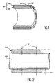
- the hoop 12 comprises at least one fiber 14 wound around the ring metallic 10 and embedded in a resin matrix 16 polymerized.
- the fiber or fibers 14 wound around the metal ring 10 are carbon fibers.
- the internal diameter of the hoop 12 is less than or equal to the outside diameter of the metal ring 10 that one wishes to introduce in the room.
- the composite ring 18 is first performed, then it is introduced into the room.
- the metal ring 10 is mounted in the hoop 12 before being introduced into the part.
- the composite ring 18 can be introduced either in the finished part or in the current part Manufacturing.
- the hoop 12 is first introduced into the part, during its manufacture. It is only then when the organic matrix of the piece is polymerized as the metal ring 10 is mounted in the hoop 12.
- the fret 12 is produced separately from the metal ring 10.
- the mounting of the metal ring 10 in the hoop 12 takes place after having cooled the metal ring enough to temporarily decrease the outside diameter.
- the fiber or fibers 14 wound on the mandrel can be pre-impregnated with resin or dry.
- the hoop 12 obtained is then mounted on the metal ring 10 that one wishes to introduce in the room in matrix composite material organic.
- a cooling operation is carried out of the metal ring 10, sufficient for the outer diameter of this ring becomes smaller to the inner diameter of the hoop 12.
- This cooling can in particular be obtained by soaking the metal ring 10 in liquid nitrogen.
- the fitting of the hoop 12 on the metal ring 10 can then be carried out easily.
- the ring metal 10 is permanently locked inside the fret 12.
- the composite ring 18 obtained by the process manufacturing which has just been described is then introduced into the composite material part to organic matrix, preferably during the manufacturing of this piece, either at the end of this manufacturing.
- the composite material part with organic matrix is produced according to the technique RTM.
- the mold is then put under vacuum and a low viscosity resin is injected into the mold under low pressure.
- a polymerization cycle is then applied to the resin, inside the mold.
- the latter is then cooled, then opened, to extract the part obtained.
- the advantages noted previously in the case of a part obtained by the conventional draping process are found in this case.
- the advantage arising from the non-expansion of the metal ring 10 during the polymerization cycle is even more sensitive, because the polymerization temperature resins used in the RTM process is more higher than when using conventional techniques draping.
- the exhibits likely to be obtained by the RTM technique are frequently parts of complex geometry such as housings and housings, in which one inserts frequently metallic elements such as rings.
- the composite ring 18 includes a hoop 12 encircling a metal ring 10 constituted by the outer ring of a ball bearing 22.
- the hoop 12 of the composite ring 18 has been integrated into a one-piece hub 24 of matrix composite material organic, during the molding step of this part as part of the RTM technique.
- hoop 12 prevents expansion of the ring metallic 10, which would normally occur when these temperature variations. Therefore, expansion of the composite material part and the composite ring 18 are substantially the same. he there is therefore practically no risk of deformation of the part in composite material with organic matrix by the metal ring.
- the ring composite 18 is preferably integrated in the room during the manufacturing thereof. Alternatively, it however, this integration is possible after manufacturing the part, in the first mode for carrying out the invention.
- the manufactured part has advantageously a recess substantially the size of the composite ring.
- Superficial machining of the wall of this recess allows the ring to be introduced composite, without significant damage to the fibers entering into the composition of the material part organic matrix composite.
- the hoop 12 is introduced into the part, during the manufacture thereof. It can be done using the traditional draping technique, or using the RTM technique. In the latter case, the hoop 12 is placed in the mold, with the preform of dry fiber. Whatever technique is used, the metal ring 10 is not placed in the hoop 12, to form the composite ring 18, only when the resin forming the composite matrix of the part was polymerized.
Landscapes
- Engineering & Computer Science (AREA)
- Mechanical Engineering (AREA)
- General Engineering & Computer Science (AREA)
- Chemical & Material Sciences (AREA)
- Composite Materials (AREA)
- Manufacturing & Machinery (AREA)
- Moulding By Coating Moulds (AREA)
Claims (11)
- Verfahren zum Einführen eines metallischen Rings (10) in ein Teil aus Verbundmaterial mit organischer Matrix, wobei das Verfahren dadurch gekennzeichnet ist, dass es die folgenden Schritte umfasst:getrennte Herstellung eines Bundrings bzw. einer Umwickelung (12) mit mindestens einer gewickelten Faser (14), die einen Innendurchmesser aufweist, der gleich oder kleiner dem Außendurchmesser des metallischen Rings (10) ist,Montage des metallischen Rings (10) in dem Bundring (12) durch Abkühlen des Rings derart, dass ein Verbundring (18) gebildet wird, der einen Dehnungskoeffizienten aufweist, der im wesentlichen gleich demjenigen des (Verbundmaterial-)Teils ist.
- Verfahren nach Anspruch 1, wobei die Montage des metallischen Rings (10) in dem Bundring (12) einem Schritt des Einsetzens des Verbundrings (18) in das fertiggestellte oder in der Herstellung befindliche Teil vorausgeht.
- Verfahren nach Anspruch 1, wobei der Bundring (12) im Verlauf der Herstellung in das Teil eingesetzt wird und anschließend die Montage des metallischen Rings (10) in dem Bundring (12) nach einem Polymerisierungsschritt der organischen Matrix des Teils ausgeführt wird.
- Verfahren nach einem der Ansprüche 1 bis 3, wobei der Bundring (12) hergestellt wird, indem mindestens eine mit Harz vorgetränkte Faser (14) auf einen Dorn aufgewickelt, das Harz polymerisiert und dann der Dorn von dem so gebildeten Bundring getrennt wird.
- Verfahren nach einem der Ansprüche 1 bis 3, wobei der Bundring (12) hergestellt wird, indem mindestens eine trockene Faser (14) auf einen Dorn aufgewickelt, die Faser mit Harz getränkt, das Harz polymerisiert und dann der Dorn von dem so gebildeten Bundring getrennt wird.
- Verfahren nach einem der vorangehenden Ansprüche, wobei ein rohrförmiger Bundring (12') hergestellt wird, der auf die Länge des metallischen Rings (10) abgelängt wird.
- Verfahren nach einem der vorangehenden Ansprüche, wobei Kohlenstofffasern zur Herstellung des Bundrings (12) verwendet werden.
- Verfahren nach einem der Ansprüche 1 oder 2, wobei der Verbundring (18) in einen zu diesem Zweck in dem fertiggestellten Teil vorgesehenen Sitz eingesetzt wird.
- Verfahren nach einem der Ansprüche 1 bis 7, wobei der Bundring (12) oder der Verbundring (18) sowie eine Vorform getrockneter Fasern in eine Form eingebracht werden, welche die Form des herzustellenden Teils aufweist, das Harz in die Form gegossen, dieses Harz polymerisiert, die Form abgekühlt, diese geöffnet und das fertiggestellte Teil aus ihr entnommen wird.
- Teil aus Verbundmaterial mit organischer Matrix, mit mindestens einem in das Material eingesetzten metallischen Ring (10), wobei das Teil dadurch gekennzeichnet ist, dass der metallische Ring (10) von einem Bundring (12) umgeben ist, der mindestens eine um den metallischen Ring gewickelte und in einer polymerisierten Harzmatrix (16) getränkte Faser(14) aufweist, wobei der metallische Ring (10) und der Bundring (14), der diesen umgibt, einen Verbundring (18) mit einem Dehnungskoeffizienten bilden, der im wesentlichen gleich demjenigen des Teils ist.
- Teil nach Anspruch 10, wobei die Faser (14) eine Kohlenstofffaser ist.
Applications Claiming Priority (2)
| Application Number | Priority Date | Filing Date | Title |
|---|---|---|---|
| FR9909090A FR2796425B1 (fr) | 1999-07-13 | 1999-07-13 | Procede d'introduction d'une bague mettalique dans une piece en materiau composite a matrice organique et piece obtenue par ce procede |
| FR9909090 | 1999-07-13 |
Publications (2)
| Publication Number | Publication Date |
|---|---|
| EP1068926A1 EP1068926A1 (de) | 2001-01-17 |
| EP1068926B1 true EP1068926B1 (de) | 2004-10-13 |
Family
ID=9548057
Family Applications (1)
| Application Number | Title | Priority Date | Filing Date |
|---|---|---|---|
| EP00401983A Expired - Lifetime EP1068926B1 (de) | 1999-07-13 | 2000-07-10 | Verfahren zum Einbringen eines metallischen Rings in Verbundmaterial mit organischer Matrix und dadurch erhaltenes Bauteil |
Country Status (3)
| Country | Link |
|---|---|
| EP (1) | EP1068926B1 (de) |
| DE (1) | DE60014787T2 (de) |
| FR (1) | FR2796425B1 (de) |
Families Citing this family (8)
| Publication number | Priority date | Publication date | Assignee | Title |
|---|---|---|---|---|
| DE10124023C1 (de) | 2001-05-17 | 2002-11-07 | Kuka Roboter Gmbh | Faserverstärktes Kunststoffteil |
| DE102009011585A1 (de) * | 2009-03-06 | 2010-09-09 | Frank, Egon, Dr. | Bauteil und Verfahren zu seiner Herstellung |
| DE102010051840A1 (de) * | 2010-11-18 | 2012-05-24 | Schaeffler Technologies Gmbh & Co. Kg | Lagerring |
| WO2012160026A1 (en) * | 2011-05-20 | 2012-11-29 | Aktiebolaget Skf | Bearing with fiber composite rings |
| US8882125B2 (en) * | 2011-12-09 | 2014-11-11 | Specialized Bicycle Components, Inc. | Bicycle assembly with bottom bracket shell |
| DE102013215170A1 (de) * | 2013-08-01 | 2015-02-05 | Aktiebolaget Skf | Röhrenförmiger Körper zur Montage auf einer Welle oder in einer Bohrung und Verfahren zur Montage |
| US11713803B1 (en) * | 2022-04-29 | 2023-08-01 | GM Global Technology Operations LLC | Carbon fiber composite drive unit housings for electric vehicles |
| CN118404833B (zh) * | 2024-06-24 | 2024-09-17 | 中南大学 | 一种提高树脂基复合材料加工质量的复合成型方法 |
Family Cites Families (9)
| Publication number | Priority date | Publication date | Assignee | Title |
|---|---|---|---|---|
| US2476982A (en) * | 1945-08-25 | 1949-07-26 | Virgil L Iles | Rolling contact bearing |
| GB812030A (en) * | 1956-10-17 | 1959-04-15 | Continental Motors Corp | Engine gudgeon pin assembly or like article of manufacture |
| DE2400902C2 (de) * | 1974-01-09 | 1982-05-27 | A. Friedr. Flender Gmbh & Co Kg, 4290 Bocholt | Wälzlagereinbau |
| GB2080443B (en) * | 1980-07-18 | 1984-09-12 | Lamb Co F Jos | Bearing assembly for machine tool spindles |
| DE3220193A1 (de) * | 1982-05-28 | 1983-12-01 | Metzeler Kautschuk GmbH, 8000 München | Verfahren zum einbringen eines ringkoerpers fuer einen torsionsschwingstilger |
| JPS618230A (ja) * | 1984-06-22 | 1986-01-14 | Hitachi Metals Ltd | 鋼部材にセラミツクス部品を固定する方法 |
| GB8925103D0 (en) * | 1989-11-07 | 1989-12-28 | Courtaulds Plc | Improved roller |
| CA2043519C (en) * | 1990-05-31 | 1998-11-24 | Takao Umezawa | Motor casing made of resin and method of manufacturing the same |
| DE4326177A1 (de) * | 1992-08-10 | 1994-02-17 | Volkswagen Ag | Verfahren zum Herstellen einer Lageranordnung |
-
1999
- 1999-07-13 FR FR9909090A patent/FR2796425B1/fr not_active Expired - Lifetime
-
2000
- 2000-07-10 DE DE60014787T patent/DE60014787T2/de not_active Expired - Lifetime
- 2000-07-10 EP EP00401983A patent/EP1068926B1/de not_active Expired - Lifetime
Also Published As
| Publication number | Publication date |
|---|---|
| FR2796425A1 (fr) | 2001-01-19 |
| FR2796425B1 (fr) | 2001-10-19 |
| EP1068926A1 (de) | 2001-01-17 |
| DE60014787T2 (de) | 2006-03-09 |
| DE60014787D1 (de) | 2004-11-18 |
Similar Documents
| Publication | Publication Date | Title |
|---|---|---|
| EP2640566B1 (de) | Verfahren zur herstellung einer feder aus einem verbundwerkstoff, etwa eine aufhängungsfeder insbesondere für ein kraftfahrzeug | |
| EP0761978B1 (de) | Rotor aus thermostrukturellem Verbundmaterial, insbesondere mit grossem Diameter und sein Herstellungsverfahren | |
| EP0761977B1 (de) | Rotor aus hochtemperaturbeständige Verbundwerkstoff, insbesondere mit kleinem Diameter und sein Herstellungsverfahren | |
| EP3204220B1 (de) | Werkzeug zur herstellung eines verbundwerkstoffs mit einer organischen matrix | |
| EP2077183A1 (de) | Verbundflansch mit Verarbeitungsteil | |
| WO2011131908A1 (fr) | Dispositif de fabrication d'un carter en materiau composite et procede de fabrication mettant en œuvre un tel dispositif | |
| EP2707199A1 (de) | Verdichtungs- und spritzgiessform für faservorformling zur herstellung einer turbomaschinen- gleichrichterschaufel aus verbundstoff | |
| WO2011036380A1 (fr) | Procede et moule de fabrication d' une aube de turbomachine en materiau compos ite | |
| EP3578760B1 (de) | Eine fanschaufel aus verbundwerkstoff mit grossem spiel | |
| EP1068926A1 (de) | Verfahren zum Einbringen eines metallischen Rings in Verbundmaterial mit organischer Matrix und dadurch erhaltenes Bauteil | |
| FR3026980A1 (fr) | Procede d'immobilisation d'une preforme dans un moule | |
| CA2971421A1 (fr) | Outillage et procede d'impregnation d'une preforme fibreuse de revolution | |
| WO2016062952A1 (fr) | Assemblage par un element d'ancrage mecanique entre deux pieces dont l'une est realisee en materiau composite | |
| WO2023041861A1 (fr) | Cale de compactage d'un moule de carter de soufflante | |
| EP3057773B1 (de) | Verfahren zum verbinden einer schürze mit einem motorblockgehäuse | |
| FR2989020A1 (fr) | Procede de fabrication d'une piece epaisse de turbomachine en materiau composite par injection de resine sous pression | |
| FR2949091A1 (fr) | Procede de realisation d'un disque aubage monobloc creux | |
| FR3071755A1 (fr) | Element d'insertion, utilisable lors du coulage d'un bloc-cylindres, et son procede de fabrication | |
| EP1260293B1 (de) | Verfahren zur Herstellung einer Metall-Matrix-Composite Rohr-Platte Anordnung | |
| EP4161751A1 (de) | Injektionswerkzeug für ein tonnenförmiges rotierendes teil | |
| FR2541374A1 (fr) | Piston composite pour moteur a combustion interne | |
| WO2020201132A1 (fr) | Fabrication d'un réservoir à gaz sous haute pression | |
| FR3153555A1 (fr) | Procédé de fabrication d’une pièce en matériau composite | |
| FR3144938A1 (fr) | Procede de fabrication d’une piece en materiau composite et piece ainsi fabriquee | |
| FR3162804A1 (fr) | Cage de palier à roulement en matériau composite ayant une cohésion interlaminaire améliorée et unité de palier à roulement associée et procédé |
Legal Events
| Date | Code | Title | Description |
|---|---|---|---|
| PUAI | Public reference made under article 153(3) epc to a published international application that has entered the european phase |
Free format text: ORIGINAL CODE: 0009012 |
|
| AK | Designated contracting states |
Kind code of ref document: A1 Designated state(s): DE GB IT |
|
| AX | Request for extension of the european patent |
Free format text: AL;LT;LV;MK;RO;SI |
|
| 17P | Request for examination filed |
Effective date: 20010704 |
|
| AKX | Designation fees paid |
Free format text: DE GB IT |
|
| RAP1 | Party data changed (applicant data changed or rights of an application transferred) |
Owner name: EADS CCR |
|
| GRAP | Despatch of communication of intention to grant a patent |
Free format text: ORIGINAL CODE: EPIDOSNIGR1 |
|
| GRAS | Grant fee paid |
Free format text: ORIGINAL CODE: EPIDOSNIGR3 |
|
| GRAA | (expected) grant |
Free format text: ORIGINAL CODE: 0009210 |
|
| AK | Designated contracting states |
Kind code of ref document: B1 Designated state(s): DE GB IT |
|
| REG | Reference to a national code |
Ref country code: GB Ref legal event code: FG4D Free format text: NOT ENGLISH |
|
| REF | Corresponds to: |
Ref document number: 60014787 Country of ref document: DE Date of ref document: 20041118 Kind code of ref document: P |
|
| GBT | Gb: translation of ep patent filed (gb section 77(6)(a)/1977) |
Effective date: 20050222 |
|
| PLBE | No opposition filed within time limit |
Free format text: ORIGINAL CODE: 0009261 |
|
| STAA | Information on the status of an ep patent application or granted ep patent |
Free format text: STATUS: NO OPPOSITION FILED WITHIN TIME LIMIT |
|
| 26N | No opposition filed |
Effective date: 20050714 |
|
| PGFP | Annual fee paid to national office [announced via postgrant information from national office to epo] |
Ref country code: IT Payment date: 20120726 Year of fee payment: 13 |
|
| PG25 | Lapsed in a contracting state [announced via postgrant information from national office to epo] |
Ref country code: IT Free format text: LAPSE BECAUSE OF NON-PAYMENT OF DUE FEES Effective date: 20130710 |
|
| PGFP | Annual fee paid to national office [announced via postgrant information from national office to epo] |
Ref country code: DE Payment date: 20140721 Year of fee payment: 15 |
|
| PGFP | Annual fee paid to national office [announced via postgrant information from national office to epo] |
Ref country code: GB Payment date: 20140721 Year of fee payment: 15 |
|
| REG | Reference to a national code |
Ref country code: DE Ref legal event code: R119 Ref document number: 60014787 Country of ref document: DE |
|
| GBPC | Gb: european patent ceased through non-payment of renewal fee |
Effective date: 20150710 |
|
| PG25 | Lapsed in a contracting state [announced via postgrant information from national office to epo] |
Ref country code: GB Free format text: LAPSE BECAUSE OF NON-PAYMENT OF DUE FEES Effective date: 20150710 Ref country code: DE Free format text: LAPSE BECAUSE OF NON-PAYMENT OF DUE FEES Effective date: 20160202 |