EP1068933B1 - Cheville d'ancrage expansif - Google Patents
Cheville d'ancrage expansif Download PDFInfo
- Publication number
- EP1068933B1 EP1068933B1 EP20000810586 EP00810586A EP1068933B1 EP 1068933 B1 EP1068933 B1 EP 1068933B1 EP 20000810586 EP20000810586 EP 20000810586 EP 00810586 A EP00810586 A EP 00810586A EP 1068933 B1 EP1068933 B1 EP 1068933B1
- Authority
- EP
- European Patent Office
- Prior art keywords
- shaft
- sleeve
- disassembling device
- adapter piece
- undercut
- Prior art date
- Legal status (The legal status is an assumption and is not a legal conclusion. Google has not performed a legal analysis and makes no representation as to the accuracy of the status listed.)
- Expired - Lifetime
Links
- 238000004873 anchoring Methods 0.000 title description 4
- 230000008878 coupling Effects 0.000 claims description 11
- 238000010168 coupling process Methods 0.000 claims description 11
- 238000005859 coupling reaction Methods 0.000 claims description 11
- 238000003780 insertion Methods 0.000 claims description 6
- 230000037431 insertion Effects 0.000 claims description 6
- 238000005553 drilling Methods 0.000 description 4
- 238000000034 method Methods 0.000 description 4
- 238000010079 rubber tapping Methods 0.000 description 4
- 230000004323 axial length Effects 0.000 description 2
- 238000011161 development Methods 0.000 description 2
- 230000018109 developmental process Effects 0.000 description 2
- 238000004519 manufacturing process Methods 0.000 description 2
- 238000003892 spreading Methods 0.000 description 2
- 238000005520 cutting process Methods 0.000 description 1
- 230000001419 dependent effect Effects 0.000 description 1
- 238000007689 inspection Methods 0.000 description 1
- 230000001404 mediated effect Effects 0.000 description 1
- 238000002360 preparation method Methods 0.000 description 1
Images


Classifications
-
- B—PERFORMING OPERATIONS; TRANSPORTING
- B25—HAND TOOLS; PORTABLE POWER-DRIVEN TOOLS; MANIPULATORS
- B25B—TOOLS OR BENCH DEVICES NOT OTHERWISE PROVIDED FOR, FOR FASTENING, CONNECTING, DISENGAGING OR HOLDING
- B25B31/00—Hand tools for applying fasteners
Definitions
- the invention relates to a disassembly device for positively anchored dowels, in particular for undercut anchors having an anchor rod with a conically widening towards the free end head and a sleeve with radially expansible Sp Drownlappen.
- undercut anchors that are anchored in well-prepared holes or that automatically create an undercut in the prepared hole during the anchoring process.
- the known undercut anchors usually have an anchor rod with a head part, which widens substantially conically in the direction of the free end.
- a sleeve with a spreading region is axially displaceable along the anchor rod. The spreading of the sleeve is provided with a number of spaced apart by axial slots Sp Drlllappen, which are radially expelled by driving the sleeve on the conical head.
- Self-tapping undercut anchors have on the lateral surface of the expansion lobe cutting body, which edit the borehole wall abrasive when rotating the sleeve on the conical head and thereby create an undercut in the borehole deepest area of the prepared hole.
- Such a self-tapping undercut anchor is for example from the US-A-4,702,654 known.
- Object of the present invention is therefore to provide a device that allows partially or completely anchored in the subsurface undercut anchors completely disassembled when needed.
- the device should have a robust and self-explanatory design and be easy to use.
- a disassembly device according to the preamble of claim 1 is of document DE 197 12 174 known.
- the dismantling device comprises a sleeve-shaped support part, which has at its one, a support shoulder forming end of an axially projecting latch extension, which is equipped with load application means.
- the load application means are engageable with correspondingly formed load engagement means at the rear end of the sleeve of the anchor in a tensile loadable operative connection.
- the support member has an at least partially provided with an internal thread through hole which extends through the latch extension and serves to receive a shaft provided with an external thread, which is axially displaceable by rotation relative to the support member.
- the shaft has two longitudinal ends with identically shaped coupling elements for an adapter piece, whose one longitudinal section has an outer diameter which is smaller than the inner diameter of the through hole of the support part and at the free end with a matched to the coupling elements of the shaft Connecting part is equipped.
- the opposite longitudinal end of the adapter piece is designed as a plug-in end for the tool holder of a hand tool machine, in particular a rotary drilling machine.
- the inventive disassembly allows for the first time a simple and reliable, complete disassembly of partially or completely anchored in the ground undercut dowels.
- These can be conventional undercut anchors that are anchored in holes with already prepared undercuts, or self-tapping systems that produce an undercut only when anchored in the borehole deepest area of the bore.
- the cooperating in the through hole with the internal thread shaft is spindle-shaped relative to the support member slidably.
- an adapter piece which is selectively engageable with one or the other longitudinal end of the shaft.
- For disassembly of the latch extension is so connected to the rear end of the sleeve of the undercut anchor that the connection remains in tension.
- the support part is supported in the area around the bore mouth on a component or on the ground.
- the adapter piece is coupled to that end of the shaft which faces away from the latch extension. Due to the rotation of the shaft about its longitudinal axis, it is axially displaced relative to the support part until it comes into contact with the end face of the anchor rod of the undercut anchor. In the further axial adjustment of the shaft, a tensile force is exerted on the sleeve of the undercut anchor, which ultimately causes the sleeve is pulled out of the hole. After removing the disassembly device and the anchor rod can be removed from the hole. Thereafter, the adapter piece is coupled to the second end of the shaft, and the shaft is returned by axial rotation back to its original position.
- the adapter piece thus offers the advantage that it can be used for the actual disassembly process and by simply coupling at the other end of the shaft for the subsequent resetting of the shaft in the initial state.
- the coupling elements are formed at the longitudinal ends of the shaft as axially projecting pins, which have a deviating from the circular cross-section.
- the connecting part on the adapter piece is then advantageously a blind hole with a corresponding cross section to the pin.
- a special simple and proven geometry for the coupling parts and the blind hole represents the hexagon.
- the longitudinal part of the adapter piece carrying the connecting part is separated by a circumferential collar from the section having the insertion end.
- the outer diameter of the circumferential collar is greater than the inner diameter of the through hole of the sleeve-shaped support member.
- the length of the adapter piece carrying the connection part has a length which is matched to the dimensions of the support part, it is ensured that the shaft is returned to an optimum position for the next disassembly operation.
- An additional preparation of the disassembly device for use can be omitted.
- the measured from the circumferential collar to the free end of the adapter piece length is about 20 mm to about 200 mm, preferably 30 mm to 130 mm.
- the load application means on the latch extension of the support part are radially projecting pins which can be positively locked in correspondingly formed, undercut recesses at the rear end of the sleeve of the undercut anchor.
- the selected geometry of the load application means on the latch extension is easy to manufacture, robust, self-explanatory and easily coupled with the load application means at the rear end of the sleeve of the undercut anchor.
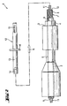
- Disassembly device shown in different states is in each case provided with the reference numeral 1 in its entirety. It comprises a sleeve-shaped support member, which may have, for reasons of better handling and weight reasons, for example, the dumbbell shape shown.
- the one front end of the support part forms an annular support shoulder 3.
- From the front end protrudes a latch extension 4, which has two or more, preferably designed as radial pins 5, load application.
- a through hole 6 extends over the entire axial length of the sleeve-shaped support part 2 and continues through the latch extension 4.
- the through hole 6 has an inner diameter i and is at least partially formed as an internally threaded bore.
- through hole 6 is provided over its entire length with an internal thread.
- the through hole 6 serves to receive a shaft 7, which is equipped over its entire axial length with an external thread 8.
- the external thread 8 of the shaft 7 cooperates with the internally threaded bore 6, so that the shaft 7 is axially adjustable by rotation relative to the support member 2 spindle-like.
- the shaft 7 has at its two longitudinal ends 9, 10 identically shaped coupling elements 11, which are formed for example by pins with hexagonal cross-section. The shaft 7 can thus be screwed in any orientation into the internally threaded bore 6 of the support part 2.
- the coupling elements 11 can be connected to a connection part 14 of an adapter piece 12.
- the connection part 14 is formed for example as a blind hole having a hexagon socket, which is matched to the hexagon of the pins 11 at the longitudinal ends 9, 10 of the shaft 7.
- the longitudinal portion 13 of the adapter piece 12 having the connection part 14 preferably has an outer diameter a, which is smaller than the inner diameter i of the through-hole 6 in the support part 2.
- a circumferential collar 16 separates the front longitudinal portion 13 of the adapter part from the rear portion, which is formed as a insertion end 15 for the tool holder of a rotary drilling rig.
- the circumferential collar 16 has an outer diameter o, which is greater than the inner diameter i of the through hole 6 in the support part 2.
- the length of the longitudinal portion 13 is denoted by l and is about 20 mm to about 200 mm, preferably 30 mm to 130 mm.
- Fig. 1 shows the disassembly device 1 in its initial position before the load application means 5 are latched to the latch extension 4 with the corresponding load engagement means on the sleeve of the undercut anchor to be disassembled.
- the rear longitudinal end 9 of the shaft 7 projects beyond the rear end face of the support part 2.
- the adapter piece 12 is with its insertion end 15 in the tool holder of a rotary drilling machine clamped and then coupled via the blind hole 14 with the coupling pin 11 at the rear longitudinal end 9 of the shaft 7. This is indicated by the arrow P.
- the shaft 7 is further screwed into the through hole 6 until the pin 11 is present at its front longitudinal end 10 on the protruding from the borehole anchor rod of the undercut anchor.
- a tensile force is exerted on the sleeve of the undercut anchor by the support member 2.
- the sleeve is finally pulled out of the hole.
- the anchor rod of the undercut dowel can be removed from the bore.
- Fig. 2 shows the disassembly device 1 immediately after disassembly of the sleeve of the undercut anchor.
- the shaft 7 is almost completely screwed into the support part 2.
- Her front longitudinal end 10 projects beyond the latch extension 4.
- To screw back the shaft 7 in its initial position with its insertion end 15 clamped in the tool holder of the rotary drill adapter piece 12 is coupled via the blind hole 14 with hexagon socket on the pin 11 at the front longitudinal end 10 of the shaft 7. This is in Fig. 2 indicated by the arrow R.
- the rotation of the shaft 7, this is returned to its original position.
- Fig. 3 shows the disassembly tool 1 immediately before the shaft 7 has reached its original position again.
- the circumferential collar 16 on the adapter part 12 is located in the immediate vicinity of the load application means 5 on the latch extension 4. Upon further turning back of the shaft 7 in the support part 2 of the collar 16 comes into contact with the latch extension 4. Thus, the blind hole 14 and the pin 11 come on front longitudinal end 10 of the shaft automatically out of engagement and the rotation of the adapter part 12 is not transmitted to the shaft 7.
Landscapes
- Engineering & Computer Science (AREA)
- Mechanical Engineering (AREA)
- Joining Of Building Structures In Genera (AREA)
- Processing Of Stones Or Stones Resemblance Materials (AREA)
- Piles And Underground Anchors (AREA)
- Dowels (AREA)
Claims (6)
- Dispositif de dépose pour chevilles ancrées par complémentarité de formes, en particulier pour dispositifs d'ancrage à contre-dépouille comportant une tige d'ancrage pourvue d'une partie de tête élargie coniquement vers l'extrémité libre et d'un manchon avec pattes expansibles à déploiement radial, comprenant une partie d'appui en forme de manchon (2) qui comporte, à l'une de ses extrémités formant un épaulement d'appui (3), un prolongement de verrouillage (4) qui dépasse axialement et qui est muni de moyens d'application de charge (5) pouvant être amenés en liaison active sollicitable en traction avec des moyens d'application de charge de conformation correspondante situés à l'extrémité arrière du manchon de la cheville, et comprenant un trou débouchant (6) qui est muni au moins par endroits d'un taraudage, qui traverse le prolongement de verrouillage (4) et qui sert à recevoir un arbre (7), lequel est muni d'un filetage extérieur (8) et est déplaçable axialement par rotation par rapport à la partie d'appui (4), caractérisé en ce que le dispositif de dépose comporte un adaptateur (12) et en ce que l'arbre (7) possède deux extrémités longitudinales (9, 10) à éléments d'accouplement de conformation identique (11) pour l'adaptateur (12) dont l'une des portions longitudinales (13) présente un diamètre extérieur (a) inférieur au diamètre intérieur (i) du trou débouchant (6) de la partie d'appui (4) et muni à extrémité longitudinale d'un raccord (14) adapté aux éléments d'accouplement de l'arbre et dont l'autre extrémité longitudinale opposée est conformée en extrémité d'insertion (15) pour le raccord d'outil d'un appareil portatif, en particulier d'un appareil de forage par rotation.
- Dispositif de dépose selon la revendication 1,
caractérisé en ce que les éléments d'accouplement (11) situés aux extrémités longitudinales (9, 10) de l'arbre (7) sont des tourillons en saillie axiale présentant une section transversale qui diffère de la forme circulaire, et le raccord (14) situé sur l'adaptateur (12) est un trou borgne dont la section transversale correspond à celle des tourillons (11). - Dispositif de dépose selon la revendication 2,
caractérisé en ce que les tourillons (11) sont conformés en hexagones, et le trou borgne (14) est conformé en hexagone femelle. - Dispositif de dépose selon une des revendications précédentes, caractérisé en ce que la portion longitudinale (13) portant le raccord (14) est séparée de la portion de l'adaptateur (12) pourvue de l'extrémité d'insertion (15) par un collet périphérique (16) dont le diamètre extérieur (o) est supérieur au diamètre intérieur (i) du trou débouchant (6) du manchon d'appui.
- Dispositif de dépose selon la revendication 4,
caractérisé en ce que la portion longitudinale (13) de l'adaptateur (12) pourvue du raccord (14) possède une longueur (1) qui, mesurée du collet périphérique (16) à l'extrémité libre, est d'environ 20 mm à environ 200 mm, de préférence de 30 mm à 130 mm. - Dispositif de dépose selon une des revendications précédentes, caractérisé en ce que les moyens d'application de charge (5) situés sur le prolongement de verrouillage (4) de la partie d'appui (2) sont des broches en saillie radiale qui sont encliquetables par complémentarité de formes dans des évidements à contre-dépouille de conformation correspondante ménagés à l'extrémité arrière du manchon du dispositif d'ancrage à contre-dépouille.
Applications Claiming Priority (2)
| Application Number | Priority Date | Filing Date | Title |
|---|---|---|---|
| DE1999132863 DE19932863A1 (de) | 1999-07-14 | 1999-07-14 | Demontagevorrichtung für formschlüssig verankernden Dübel |
| DE19932863 | 1999-07-14 |
Publications (3)
| Publication Number | Publication Date |
|---|---|
| EP1068933A2 EP1068933A2 (fr) | 2001-01-17 |
| EP1068933A3 EP1068933A3 (fr) | 2002-09-04 |
| EP1068933B1 true EP1068933B1 (fr) | 2008-04-09 |
Family
ID=7914722
Family Applications (1)
| Application Number | Title | Priority Date | Filing Date |
|---|---|---|---|
| EP20000810586 Expired - Lifetime EP1068933B1 (fr) | 1999-07-14 | 2000-07-05 | Cheville d'ancrage expansif |
Country Status (4)
| Country | Link |
|---|---|
| EP (1) | EP1068933B1 (fr) |
| JP (1) | JP4531940B2 (fr) |
| CN (1) | CN1151013C (fr) |
| DE (2) | DE19932863A1 (fr) |
Families Citing this family (3)
| Publication number | Priority date | Publication date | Assignee | Title |
|---|---|---|---|---|
| DE202010005360U1 (de) | 2010-05-03 | 2010-08-19 | Itzen, Stefan | Vorrichtung zum Entfernen von Dübeln |
| CN110241802A (zh) * | 2019-05-31 | 2019-09-17 | 湖北建科国际工程有限公司 | 静力触探仪地锚 |
| CN110936326B (zh) * | 2019-11-12 | 2021-08-17 | 福建福清核电有限公司 | 一种核电厂ptr换料水箱地脚螺栓拆除方法 |
Family Cites Families (6)
| Publication number | Priority date | Publication date | Assignee | Title |
|---|---|---|---|---|
| DE3535262A1 (de) * | 1985-10-03 | 1987-04-09 | Upat Max Langensiepen Kg | Spreizanker |
| DE3940638A1 (de) * | 1989-12-08 | 1991-06-13 | Fischer Artur Werke Gmbh | Demontagevorrichtung |
| DE4104073A1 (de) * | 1991-02-11 | 1992-08-13 | Hilti Ag | Ausziehwerkzeug |
| DE19652280A1 (de) * | 1996-12-16 | 1998-06-18 | Hilti Ag | Selbstschneidender Hinterschnittdübel |
| DE19712174C2 (de) * | 1997-03-22 | 2002-10-24 | Fischer Artur Werke Gmbh | Ausziehwerkzeug für einen Spreizanker |
| DE19713541A1 (de) * | 1997-04-02 | 1998-10-08 | Fischer Artur Werke Gmbh | Demontagewerkzeug für einen Spreizdübel |
-
1999
- 1999-07-14 DE DE1999132863 patent/DE19932863A1/de not_active Withdrawn
-
2000
- 2000-07-05 EP EP20000810586 patent/EP1068933B1/fr not_active Expired - Lifetime
- 2000-07-05 DE DE50015084T patent/DE50015084D1/de not_active Expired - Lifetime
- 2000-07-07 CN CNB001204122A patent/CN1151013C/zh not_active Expired - Fee Related
- 2000-07-14 JP JP2000214205A patent/JP4531940B2/ja not_active Expired - Fee Related
Also Published As
| Publication number | Publication date |
|---|---|
| CN1280899A (zh) | 2001-01-24 |
| JP4531940B2 (ja) | 2010-08-25 |
| JP2001081773A (ja) | 2001-03-27 |
| DE50015084D1 (de) | 2008-05-21 |
| EP1068933A2 (fr) | 2001-01-17 |
| CN1151013C (zh) | 2004-05-26 |
| EP1068933A3 (fr) | 2002-09-04 |
| DE19932863A1 (de) | 2001-01-18 |
Similar Documents
| Publication | Publication Date | Title |
|---|---|---|
| DE69914975T2 (de) | Bohrer und seine Herstellungsmethode | |
| EP0068227B1 (fr) | Boulon d'ancrage | |
| EP2146813B1 (fr) | Adaptateur pour faire fonctionner une scie cloche sur une machine d'entraînement | |
| DE3335628C2 (fr) | ||
| DE112007002516T5 (de) | Bohrwerkzeug, selbstbohrender Gesteinsanker, Bohrer, Verankerungsvorrichtung für einen selbstbohrenden Gesteinsanker, Schaft für ein Bohrwerk und Endkupplung für ein Bohrwerkzeug | |
| DE19622544A1 (de) | Hinterschnittanker | |
| DE1500942B1 (de) | Anwendung einer schnellkupplung bei einer schraubverbindung | |
| EP1285172B1 (fr) | Cheville de vissage en forme de douille servant a tarauder | |
| WO2009092626A2 (fr) | Tête d'injection pour boulon d'ancrage à injection | |
| EP1068933B1 (fr) | Cheville d'ancrage expansif | |
| DE3524284C2 (de) | Befestigungsvorrichtung | |
| DE3139174C2 (de) | Ankerbolzen | |
| WO2009092632A1 (fr) | Buse d'injection | |
| WO2013131777A2 (fr) | Ancrage pour roche | |
| DE2657000A1 (de) | Bohreinheit zur herstellung von eine hinterschneidung aufweisenden bohrloechern | |
| EP3150865A1 (fr) | Cheville a frapper | |
| EP0591507A1 (fr) | Element d'assemblage par serrage du type rivet borgne | |
| EP1072346B1 (fr) | Outil de forage | |
| DE19902397C1 (de) | Sanitärarmatur, insbesondere Waschtischarmatur | |
| DE10309792B4 (de) | Maschinenelement | |
| DE2652366A1 (de) | Hinterschnitt-bohrwerkzeug | |
| DE3831666C2 (fr) | ||
| EP0750082B1 (fr) | Dispositif d'ancrage d'éléments de construction entre une surface | |
| DE3124244C2 (de) | Ankerbolzen | |
| DE19713541A1 (de) | Demontagewerkzeug für einen Spreizdübel |
Legal Events
| Date | Code | Title | Description |
|---|---|---|---|
| PUAI | Public reference made under article 153(3) epc to a published international application that has entered the european phase |
Free format text: ORIGINAL CODE: 0009012 |
|
| AK | Designated contracting states |
Kind code of ref document: A2 Designated state(s): AT BE CH CY DE DK ES FI FR GB GR IE IT LI LU MC NL PT SE |
|
| AX | Request for extension of the european patent |
Free format text: AL;LT;LV;MK;RO;SI |
|
| PUAL | Search report despatched |
Free format text: ORIGINAL CODE: 0009013 |
|
| AK | Designated contracting states |
Kind code of ref document: A3 Designated state(s): AT BE CH CY DE DK ES FI FR GB GR IE IT LI LU MC NL PT SE |
|
| AX | Request for extension of the european patent |
Free format text: AL;LT;LV;MK;RO;SI |
|
| 17P | Request for examination filed |
Effective date: 20030304 |
|
| AKX | Designation fees paid |
Designated state(s): CH DE FR GB LI |
|
| GRAP | Despatch of communication of intention to grant a patent |
Free format text: ORIGINAL CODE: EPIDOSNIGR1 |
|
| GRAS | Grant fee paid |
Free format text: ORIGINAL CODE: EPIDOSNIGR3 |
|
| GRAA | (expected) grant |
Free format text: ORIGINAL CODE: 0009210 |
|
| AK | Designated contracting states |
Kind code of ref document: B1 Designated state(s): CH DE FR GB LI |
|
| REG | Reference to a national code |
Ref country code: GB Ref legal event code: FG4D Free format text: NOT ENGLISH |
|
| REG | Reference to a national code |
Ref country code: CH Ref legal event code: EP |
|
| REF | Corresponds to: |
Ref document number: 50015084 Country of ref document: DE Date of ref document: 20080521 Kind code of ref document: P |
|
| ET | Fr: translation filed | ||
| PLBE | No opposition filed within time limit |
Free format text: ORIGINAL CODE: 0009261 |
|
| STAA | Information on the status of an ep patent application or granted ep patent |
Free format text: STATUS: NO OPPOSITION FILED WITHIN TIME LIMIT |
|
| 26N | No opposition filed |
Effective date: 20090112 |
|
| REG | Reference to a national code |
Ref country code: FR Ref legal event code: PLFP Year of fee payment: 17 |
|
| REG | Reference to a national code |
Ref country code: FR Ref legal event code: PLFP Year of fee payment: 18 |
|
| REG | Reference to a national code |
Ref country code: FR Ref legal event code: PLFP Year of fee payment: 19 |
|
| PGFP | Annual fee paid to national office [announced via postgrant information from national office to epo] |
Ref country code: FR Payment date: 20190719 Year of fee payment: 20 Ref country code: DE Payment date: 20190719 Year of fee payment: 20 |
|
| PGFP | Annual fee paid to national office [announced via postgrant information from national office to epo] |
Ref country code: GB Payment date: 20190719 Year of fee payment: 20 |
|
| PGFP | Annual fee paid to national office [announced via postgrant information from national office to epo] |
Ref country code: CH Payment date: 20190719 Year of fee payment: 20 |
|
| REG | Reference to a national code |
Ref country code: DE Ref legal event code: R071 Ref document number: 50015084 Country of ref document: DE |
|
| REG | Reference to a national code |
Ref country code: CH Ref legal event code: PL |
|
| REG | Reference to a national code |
Ref country code: GB Ref legal event code: PE20 Expiry date: 20200704 |
|
| PG25 | Lapsed in a contracting state [announced via postgrant information from national office to epo] |
Ref country code: GB Free format text: LAPSE BECAUSE OF EXPIRATION OF PROTECTION Effective date: 20200704 |