EP1068979B1 - Abgasanlage - Google Patents
Abgasanlage Download PDFInfo
- Publication number
- EP1068979B1 EP1068979B1 EP00109490A EP00109490A EP1068979B1 EP 1068979 B1 EP1068979 B1 EP 1068979B1 EP 00109490 A EP00109490 A EP 00109490A EP 00109490 A EP00109490 A EP 00109490A EP 1068979 B1 EP1068979 B1 EP 1068979B1
- Authority
- EP
- European Patent Office
- Prior art keywords
- exhaust system
- supporting device
- silencer
- combustion engine
- resilient elements
- Prior art date
- Legal status (The legal status is an assumption and is not a legal conclusion. Google has not performed a legal analysis and makes no representation as to the accuracy of the status listed.)
- Expired - Lifetime
Links
Images
Classifications
-
- F—MECHANICAL ENGINEERING; LIGHTING; HEATING; WEAPONS; BLASTING
- F01—MACHINES OR ENGINES IN GENERAL; ENGINE PLANTS IN GENERAL; STEAM ENGINES
- F01N—GAS-FLOW SILENCERS OR EXHAUST APPARATUS FOR MACHINES OR ENGINES IN GENERAL; GAS-FLOW SILENCERS OR EXHAUST APPARATUS FOR INTERNAL-COMBUSTION ENGINES
- F01N13/00—Exhaust or silencing apparatus characterised by constructional features
- F01N13/18—Construction facilitating manufacture, assembly, or disassembly
- F01N13/1805—Fixing exhaust manifolds, exhaust pipes or pipe sections to each other, to engine or to vehicle body
- F01N13/1811—Fixing exhaust manifolds, exhaust pipes or pipe sections to each other, to engine or to vehicle body with means permitting relative movement, e.g. compensation of thermal expansion or vibration
- F01N13/1822—Fixing exhaust manifolds, exhaust pipes or pipe sections to each other, to engine or to vehicle body with means permitting relative movement, e.g. compensation of thermal expansion or vibration for fixing exhaust pipes or devices to vehicle body
-
- B—PERFORMING OPERATIONS; TRANSPORTING
- B60—VEHICLES IN GENERAL
- B60K—ARRANGEMENT OR MOUNTING OF PROPULSION UNITS OR OF TRANSMISSIONS IN VEHICLES; ARRANGEMENT OR MOUNTING OF PLURAL DIVERSE PRIME-MOVERS IN VEHICLES; AUXILIARY DRIVES FOR VEHICLES; INSTRUMENTATION OR DASHBOARDS FOR VEHICLES; ARRANGEMENTS IN CONNECTION WITH COOLING, AIR INTAKE, GAS EXHAUST OR FUEL SUPPLY OF PROPULSION UNITS IN VEHICLES
- B60K13/00—Arrangement in connection with combustion air intake or gas exhaust of propulsion units
- B60K13/04—Arrangement in connection with combustion air intake or gas exhaust of propulsion units concerning exhaust
-
- F—MECHANICAL ENGINEERING; LIGHTING; HEATING; WEAPONS; BLASTING
- F01—MACHINES OR ENGINES IN GENERAL; ENGINE PLANTS IN GENERAL; STEAM ENGINES
- F01N—GAS-FLOW SILENCERS OR EXHAUST APPARATUS FOR MACHINES OR ENGINES IN GENERAL; GAS-FLOW SILENCERS OR EXHAUST APPARATUS FOR INTERNAL-COMBUSTION ENGINES
- F01N13/00—Exhaust or silencing apparatus characterised by constructional features
- F01N13/009—Exhaust or silencing apparatus characterised by constructional features having two or more separate purifying devices arranged in series
-
- F—MECHANICAL ENGINEERING; LIGHTING; HEATING; WEAPONS; BLASTING
- F01—MACHINES OR ENGINES IN GENERAL; ENGINE PLANTS IN GENERAL; STEAM ENGINES
- F01N—GAS-FLOW SILENCERS OR EXHAUST APPARATUS FOR MACHINES OR ENGINES IN GENERAL; GAS-FLOW SILENCERS OR EXHAUST APPARATUS FOR INTERNAL-COMBUSTION ENGINES
- F01N13/00—Exhaust or silencing apparatus characterised by constructional features
- F01N13/011—Exhaust or silencing apparatus characterised by constructional features having two or more purifying devices arranged in parallel
-
- F—MECHANICAL ENGINEERING; LIGHTING; HEATING; WEAPONS; BLASTING
- F01—MACHINES OR ENGINES IN GENERAL; ENGINE PLANTS IN GENERAL; STEAM ENGINES
- F01N—GAS-FLOW SILENCERS OR EXHAUST APPARATUS FOR MACHINES OR ENGINES IN GENERAL; GAS-FLOW SILENCERS OR EXHAUST APPARATUS FOR INTERNAL-COMBUSTION ENGINES
- F01N13/00—Exhaust or silencing apparatus characterised by constructional features
- F01N13/08—Other arrangements or adaptations of exhaust conduits
- F01N13/10—Other arrangements or adaptations of exhaust conduits of exhaust manifolds
- F01N13/107—More than one exhaust manifold or exhaust collector
Definitions
- the invention relates to an exhaust system for a through gear and Engine formed engine according to the preamble of claim 1.
- the US 5,823,286 deals with an exhaust system for a through gear and Internal combustion engine formed engine, which in a construction of a motor vehicle is installed.
- the exhaust system has a trained as an elongated tubular body Silencer, is connected to the internal combustion engine and under mediation stored elastic elements.
- US-PS 4,339,919 deals with a muffler, on the one hand via an exhaust pipe with an internal combustion engine and on the other hand by means of a support device to a Frame part is held. It is between support device and frame part a compliant bearing arranged.
- an exhaust system for an internal combustion engine with several cylinders integrated into opposite rows of cylinders.
- the exhaust system includes an elongated cylindrical vessel that is under mediation a diaphragm cell is connected to the elastically suspended internal combustion engine.
- the object of the invention is an exhaust system of an internal combustion engine so hang, that they have a good vibration behavior, especially at low speeds, e.g. Has idle.
- the specially designed suspension device the exhaust system, especially one Silencer of the latter, vibration technology is optimized, such that the Idling shaking is at least reduced. Thanks to this suspension device can the idling speed of the internal combustion engine are lowered, which is advantageous on the fuel consumption, possibly also the exhaust emission of the said Internal combustion engine affects.
- the first support device and the second Support devices include well-designed components that are not only lightweight can be produced, but also grow well on the muffler or with the Have the support console connected. Finally, with the at least tensile loads receiving link an additional coupling of the muffler achieved, which causes a positive influence on the vibration behavior.
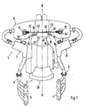
- An exhaust system 1 is for guiding exhaust gases of an internal combustion engine trained, which is locked with a gear 2 to an engine and in a built a motor vehicle is built.
- the exhaust system 1 is with exhaust devices 3, 4 at Cylinder heads of opposite cylinder rows Boxerbauart the internal combustion engine connected and via defined shaped exhaust pipes 5, 6, with catalysts 7, 8 are provided, connected to a muffler 9.
- the one by an oblong Body shown with approximately rectangular cross-section silencer 9 extends transverse to a longitudinal center plane B-B of the motor vehicle, which is also the fundamental Forming direction for the transmission 2 and the internal combustion engine forms.
- the muffler 9 is provided with a suspension device 10, at least partly with the intermediary of elastic elements 11, 12 at different Wall portions 13, 14 and 15, 16 of the muffler 9 attacks.
- the Suspension device 10 is held with screws 17, 18 on the transmission 2, which with a first free end 19 adjacent to the muffler 9; a second one End 20 of the transmission 2 connects directly to the internal combustion engine.
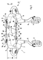
- the suspension device comprises a first support device 21 and a second one Support device 22, which is arranged at a distance A s to each other on the muffler 9 are. Both support devices 21 and 22 are interconnected via a support bracket 23 connected.
- the first support device 21 is mediated by Attachment members 24, 25 brought to the muffler 9; the second Support device 21 by means of fastening members 26, 27th
- the elastic elements 11, 12 in the Fastening members 24, 25 integrated, spaced and arranged to each other the wall portions 13, 14 of the muffler 9 are introduced. Between elastic elements 11, 12 extends a horizontal, leaf spring-like strut 28, whose longer side 29 is aligned in the vehicle height direction C-C. each elastic element e.g. 11 is formed as a cylindrical sleeve thrust spring whose Design by use of iterative and / or arithmetical measures takes place.
- the elastic elements 11, 12 of hose clamp-like Holding parts 30, 31 surrounded, the mounting flanges 32, 33 have. The Mounting flanges 32, 33 receive the strut 28, under mediation of screws 34 and 35.
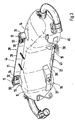
- the second supporting device 22 has the holder 37, 38 formed fastening members 26, 27, which on the wall portions 15, 16 the muffler 9 are connected.
- the holders 37, 38 are available with a Link 39 in operative connection, which may be a rope and then only Absorbs tensile loads. It is also conceivable, however, the connecting member 39 as a rod form, which transmits both tensile loads and compressive loads.
- the support bracket 22 is a dimensionally stable plate 40, with the leaf spring-like strut 28 by means of screws 41, 42 and with the connecting member 39 under Intermediate circuit of a clamping device 43 is connected.
- the Support bracket 22 practice the screws 17, 18 with the first end 18 of the transmission. 2 connected.
- the muffler 9 of the exhaust system has a top 44 and a Bottom 45 on, and the first support device 20 and the second support device 21 extend adjacent to this top 44 and this bottom 45 of the said Silencer.
Landscapes
- Engineering & Computer Science (AREA)
- Chemical & Material Sciences (AREA)
- Combustion & Propulsion (AREA)
- Mechanical Engineering (AREA)
- General Engineering & Computer Science (AREA)
- Transportation (AREA)
- Exhaust Silencers (AREA)
- Cooling, Air Intake And Gas Exhaust, And Fuel Tank Arrangements In Propulsion Units (AREA)
- Vibration Prevention Devices (AREA)
Description
- Fig. 1
- eine Ansicht von oben auf eine Abgasanlage einer Brennkraftmaschine, eingebaut in ein Kraftfahrzeug;
- Fig. 2
- eine Schrägansicht von oben auf die Abgasanlage der Fig. 1;
- Fig. 3
- eine Schrägansicht der Fig. 1 etwa in Richtung Pfeilrichtung A der Fig. 2.
Claims (9)
- Abgasanlage (1) für ein durch Getriebe (2) und Brennkraftmaschine gebildetes Triebwerk, eingebaut in ein einen Aufbau besitzendes Kraftfahrzeug, wobei die einen als länglichen Rohrkörper ausgebildeten Schalldämpfer (9) aufweisende Abgasanlage (1) mit der Brennkraftmaschine verbunden und unter Vermittlung elastischer Elemente (11, 12) gelagert ist, wobei an dem Schalldämpfer (9) eine an verschiedenen Wandungsbereichen (13, 14 und 15, 16) des Schalldämpfers (9) angreifende, die elastischen Elemente (11, 12) umfassende Aufhängungseinrichtung (10) vorgesehen ist, die mittels Befestigungsgliedern (17, 18) und vorzugsweise unabhängig vom Aufbau am Getriebe (2) und/oder der Brennkraftmaschine des Triebwerks gehalten ist, dadurch gekennzeichnet, dass die Aufhängungseinrichtung (10) mit einer ersten Stützvorrichtung (21) und einer zweiten Stützvorrichtung (22) versehen ist, die mit Abstand (As) zueinander am Schalldämpfer (9) angeordnet und untereinander über eine Tragkonsole (23) verbunden sind, wobei die elastischen Elemente (11, 12) zwischen der ersten Stützvorrichtung (21) und dem Schalldämpfer (9) angebracht sind und jede Stützvorrichtung (21 und 22) mit einem oder mehreren Befestigungsgliedern (24, 25 und 26, 27) an den Schalldämpfer (9) herangeführt ist.
- Abgasanlage nach Anspruch 1, dadurch gekennzeichnet, dass die erste Stützvorrichtung (21) zwei beabstandete als elastische Elemente (11, 12) ausgebildete Befestigungsglieder (24, 25) aufweist, die mit einer blattfederartigen Strebe (28) verbunden sind.
- Abgasanlage nach Anspruch 2, dadurch gekennzeichnet, dass jedes elastische Element (11, 12) der ersten Stützvorrichtung (21) nach Art einer zylindrischen Hülsenschubfeder ausgebildet ist.
- Abgasanlage nach den Ansprüche 2 und 3, dadurch gekennzeichnet, dass die elastischen Elemente (11, 12) der ersten Stützvorrichtung (21 ) mit schlauchklemmenartigen Halteteilen (30, 31) versehen sind, wobei zwischen Befestigungsflanschen (32, 33) dieser Halteteile (30, 31) die Strebe (28) eingesetzt und unter Vermittlung von Schrauben (34, 35) in Lage gehalten wird.
- Abgasanlage nach Anspruch 1, dadurch gekennzeichnet, dass die zweite Stützvorrichtung (22) als Halter (37, 38) ausgebildete Befestigungsglieder (26, 27) aufweist, die mit einem zumindest Zugbelastungen aufnehmenden Verbindungsglied (39) in Wirkverbindung stehen.
- Abgasanlage nach Anspruch 5, dadurch gekennzeichnet, dass das Verbindungsglied (39) ein Seil ist.
- Abgasanlage nach Anspruch 5, dadurch gekennzeichnet, dass das Verbindungsglied (39) ein Zug und Druckbelastungen aufnehmender Stab ist.
- Abgasanlage nach Anspruch 1, dadurch gekennzeichnet, dass die Tragkonsole (23) eine formsteife Platte ist, die unter Vermittlung von Schrauben (17, 18) mit dem Getriebe (2) verbunden ist.
- Abgasanlage mit einem länglichen, eine Oberseite und eine Unterseite aufweisenden Schalldämpfer nach einem oder mehreren der vorangehenden Ansprüche, dadurch gekennzeichnet, dass die erste Stützvorrichtung (21) benachbart der Oberseite (44) und die zweite Stützvorrichtung (22) benachbart der Unterseite (45) verlaufen.
Applications Claiming Priority (2)
| Application Number | Priority Date | Filing Date | Title |
|---|---|---|---|
| DE19932349 | 1999-07-10 | ||
| DE19932349A DE19932349C2 (de) | 1999-07-10 | 1999-07-10 | Abgasanlage |
Publications (3)
| Publication Number | Publication Date |
|---|---|
| EP1068979A2 EP1068979A2 (de) | 2001-01-17 |
| EP1068979A3 EP1068979A3 (de) | 2003-08-13 |
| EP1068979B1 true EP1068979B1 (de) | 2005-05-18 |
Family
ID=7914379
Family Applications (1)
| Application Number | Title | Priority Date | Filing Date |
|---|---|---|---|
| EP00109490A Expired - Lifetime EP1068979B1 (de) | 1999-07-10 | 2000-05-04 | Abgasanlage |
Country Status (4)
| Country | Link |
|---|---|
| US (1) | US6412587B1 (de) |
| EP (1) | EP1068979B1 (de) |
| JP (1) | JP2001041031A (de) |
| DE (2) | DE19932349C2 (de) |
Families Citing this family (12)
| Publication number | Priority date | Publication date | Assignee | Title |
|---|---|---|---|---|
| AU2003210997A1 (en) * | 2003-02-13 | 2004-09-09 | The Trustees Of Columbia University In The City Of New York | Micropatterning of molecular surfaces via selective irradiation |
| DE10332940B4 (de) * | 2003-07-19 | 2007-07-19 | Dr.Ing.H.C. F. Porsche Ag | Abgasanlage für eine Brennkraftmaschine eines Kraftfahrzeugs |
| JP2005214119A (ja) * | 2004-01-30 | 2005-08-11 | Toyota Motor Corp | 排気管 |
| DE102004022721A1 (de) | 2004-05-07 | 2005-11-24 | Dr.Ing.H.C. F. Porsche Ag | Zweiflutige Abgasanlage für eine Brennkraftmaschine |
| DE102004022720A1 (de) * | 2004-05-07 | 2005-11-24 | Dr.Ing.H.C. F. Porsche Ag | Abgasanlage für eine durch Getriebe und Motor gebildete Antriebseinheit |
| DE102005048839A1 (de) * | 2005-10-12 | 2007-04-26 | Daimlerchrysler Ag | Vorrichtung zur Aufhängung mindestens eines Abgasrohres eines Kraftfahrzeugs |
| JP2008062849A (ja) * | 2006-09-08 | 2008-03-21 | Toyota Industries Corp | 産業車両の排気構造 |
| JP5543563B2 (ja) * | 2012-10-16 | 2014-07-09 | 株式会社小松製作所 | 排気処理ユニット |
| DE102015010513B3 (de) * | 2015-08-13 | 2016-11-17 | Audi Ag | Befestigungsanordnung |
| DE102019116336A1 (de) * | 2019-06-17 | 2020-12-17 | Eberspächer Exhaust Technology GmbH & Co. KG | Komponente für eine Abgasanlage einer Brennkraftmaschine |
| DE102019133112A1 (de) | 2019-12-05 | 2021-06-10 | Ford Global Technologies Llc | Befestigungsvorrichtung zur Befestigung einer Komponente zur Abgasnachbehandlung eines Verbrennungsmotors |
| JP7033224B1 (ja) * | 2021-03-04 | 2022-03-09 | マレリ株式会社 | 支持部材及び触媒コンバータの支持構造 |
Family Cites Families (16)
| Publication number | Priority date | Publication date | Assignee | Title |
|---|---|---|---|---|
| US2081546A (en) * | 1934-03-29 | 1937-05-25 | Hupp Motor Car Corp | Muffler mounting |
| DE972483C (de) | 1951-12-07 | 1959-07-30 | Krauss Maffei Ag | Auspuffanlage fuer Zweitakt-Brennkraftmaschinen mit mehreren Zylinderreihen, insbesondere Zweitakt-Dieselmaschinen |
| US3746127A (en) * | 1971-08-30 | 1973-07-17 | J Leventhal | Suspension means for automobile mufflers |
| JPS581617Y2 (ja) * | 1973-07-13 | 1983-01-12 | 日産自動車株式会社 | 自動車の触媒コンバ−タ支持装置 |
| DE2415536A1 (de) * | 1974-03-30 | 1975-10-16 | Daimler Benz Ag | Halterung fuer auspuffanlagen von kraftfahrzeugen |
| GB1526963A (en) * | 1974-11-26 | 1978-10-04 | Fuji Heavy Ind Ltd | Exhaust systems for internal combustion engines |
| FR2316435A1 (fr) * | 1975-07-04 | 1977-01-28 | Peugeot | Perfectionnement aux dispositifs d'echappement des gaz d'un moteur a combustion |
| US4339919A (en) * | 1980-03-24 | 1982-07-20 | Towmotor Corporation | Flexible muffler mounting |
| JPS5863521A (ja) * | 1981-10-09 | 1983-04-15 | Nissan Motor Co Ltd | 内燃機関車両用排気系部品支持装置 |
| JPS6082438A (ja) * | 1983-10-14 | 1985-05-10 | Toyota Motor Corp | 排気装置の支持構造 |
| DE3737987A1 (de) * | 1987-11-09 | 1989-05-18 | Draebing Kg Wegu | Aufhaengeoese fuer eine abgasanlage eines kraftfahrzeugs |
| US4884399A (en) * | 1989-02-24 | 1989-12-05 | Morris James K | Exhaust system for rear-engine vehicles |
| DE4107185C1 (de) * | 1991-03-06 | 1992-06-11 | Mercedes-Benz Aktiengesellschaft, 7000 Stuttgart, De | |
| JP3451706B2 (ja) * | 1993-07-09 | 2003-09-29 | マツダ株式会社 | エンジンの排気装置 |
| JP3554362B2 (ja) * | 1994-06-14 | 2004-08-18 | 本田技研工業株式会社 | 車両における排気管系の支持構造 |
| JP3309949B2 (ja) * | 1996-03-11 | 2002-07-29 | カルソニックカンセイ株式会社 | 消音器へのブラケット取付構造 |
-
1999
- 1999-07-10 DE DE19932349A patent/DE19932349C2/de not_active Expired - Fee Related
-
2000
- 2000-05-04 EP EP00109490A patent/EP1068979B1/de not_active Expired - Lifetime
- 2000-05-04 DE DE50010334T patent/DE50010334D1/de not_active Expired - Lifetime
- 2000-07-07 JP JP2000206948A patent/JP2001041031A/ja not_active Withdrawn
- 2000-07-10 US US09/612,968 patent/US6412587B1/en not_active Expired - Fee Related
Also Published As
| Publication number | Publication date |
|---|---|
| DE19932349A1 (de) | 2001-01-18 |
| US6412587B1 (en) | 2002-07-02 |
| DE50010334D1 (de) | 2005-06-23 |
| EP1068979A3 (de) | 2003-08-13 |
| EP1068979A2 (de) | 2001-01-17 |
| DE19932349C2 (de) | 2001-08-09 |
| JP2001041031A (ja) | 2001-02-13 |
Similar Documents
| Publication | Publication Date | Title |
|---|---|---|
| DE19803243B4 (de) | Ansaugsystem eines Motors | |
| DE10307506B4 (de) | Abgasanlage | |
| DE60215422T2 (de) | Schwingungsdämpfer für Motor-Abgassystem | |
| DE3721507C2 (de) | ||
| DE19932349C2 (de) | Abgasanlage | |
| DE102016223510B4 (de) | Trägervorrichtung für einen Verbrennungsmotor eines Fahrzeugs | |
| DE3626091A1 (de) | Halterungskonstruktion fuer motorzubehoerteile | |
| DE10244891A1 (de) | V-Motor-Montagevorrichtung | |
| EP1747357B1 (de) | Abgasanlage für eine durch getriebe und motor gebildete antriebseinheit | |
| EP0749861A2 (de) | Mitnehmerscheibe zwischen einer Brennkraftmaschine der Hubkolbenbauart und einem Wandler | |
| EP0367960A2 (de) | Mehrzylindrige Brennkraftmaschine | |
| EP0580957B1 (de) | Luftfilter | |
| DE102016111301B4 (de) | Kraftfahrzeug mit Vorrichtungen zur Aufhängung eines Abgasstrang an einer Karosserie des Kraftfahrzeug | |
| DE3641811C1 (de) | Ansauganlage fuer eine vorzugsweise mehrzylindrige Brennkraftmaschine | |
| DE102008021281A1 (de) | Abgasanlage für eine Brennkraftmaschine | |
| EP1745969B1 (de) | Fahrzeug mit einer Einrichtung zur gekoppelten Befestigung einer Abgasanlage mit einer Brennkraftmaschine | |
| DE102005023265B4 (de) | Vorrichtung zur schwingungsdämpfenden Lagerung eines Antriebsaggregates | |
| DE3342820A1 (de) | Aggregate-lageranordnung | |
| DE3202256A1 (de) | Aggregatelagerung | |
| DE19959885B4 (de) | Einlassvorrichtung für einen V-Motor | |
| DE10332940B4 (de) | Abgasanlage für eine Brennkraftmaschine eines Kraftfahrzeugs | |
| DE102008021282A1 (de) | Abgasanlage für eine Brennkraftmaschine | |
| DE102018130030B4 (de) | Brennkraftmaschinenanordnung | |
| DE4307998C2 (de) | Vorrichtung zum Vermindern von Karosserieeigenschwingungen | |
| DE19810252A1 (de) | Vorrichtung zum Einspannen eines Halterohres und Halterohr für Nutzfahrzeuge |
Legal Events
| Date | Code | Title | Description |
|---|---|---|---|
| PUAI | Public reference made under article 153(3) epc to a published international application that has entered the european phase |
Free format text: ORIGINAL CODE: 0009012 |
|
| AK | Designated contracting states |
Kind code of ref document: A2 Designated state(s): AT BE CH CY DE DK ES FI FR GB GR IE IT LI LU MC NL PT SE |
|
| AX | Request for extension of the european patent |
Free format text: AL;LT;LV;MK;RO;SI |
|
| PUAL | Search report despatched |
Free format text: ORIGINAL CODE: 0009013 |
|
| AK | Designated contracting states |
Designated state(s): AT BE CH CY DE DK ES FI FR GB GR IE IT LI LU MC NL PT SE |
|
| AX | Request for extension of the european patent |
Extension state: AL LT LV MK RO SI |
|
| 17P | Request for examination filed |
Effective date: 20040213 |
|
| AKX | Designation fees paid |
Designated state(s): DE FR GB IT |
|
| 17Q | First examination report despatched |
Effective date: 20040326 |
|
| GRAP | Despatch of communication of intention to grant a patent |
Free format text: ORIGINAL CODE: EPIDOSNIGR1 |
|
| GRAS | Grant fee paid |
Free format text: ORIGINAL CODE: EPIDOSNIGR3 |
|
| GRAA | (expected) grant |
Free format text: ORIGINAL CODE: 0009210 |
|
| AK | Designated contracting states |
Kind code of ref document: B1 Designated state(s): DE FR GB IT |
|
| PG25 | Lapsed in a contracting state [announced via postgrant information from national office to epo] |
Ref country code: IT Free format text: LAPSE BECAUSE OF NON-PAYMENT OF DUE FEES Effective date: 20050518 |
|
| REG | Reference to a national code |
Ref country code: GB Ref legal event code: FG4D Free format text: NOT ENGLISH |
|
| REG | Reference to a national code |
Ref country code: IE Ref legal event code: FG4D Free format text: LANGUAGE OF EP DOCUMENT: GERMAN |
|
| REF | Corresponds to: |
Ref document number: 50010334 Country of ref document: DE Date of ref document: 20050623 Kind code of ref document: P |
|
| GBT | Gb: translation of ep patent filed (gb section 77(6)(a)/1977) |
Effective date: 20050908 |
|
| ET | Fr: translation filed | ||
| PLBE | No opposition filed within time limit |
Free format text: ORIGINAL CODE: 0009261 |
|
| STAA | Information on the status of an ep patent application or granted ep patent |
Free format text: STATUS: NO OPPOSITION FILED WITHIN TIME LIMIT |
|
| 26N | No opposition filed |
Effective date: 20060221 |
|
| PGFP | Annual fee paid to national office [announced via postgrant information from national office to epo] |
Ref country code: GB Payment date: 20070522 Year of fee payment: 8 |
|
| PGFP | Annual fee paid to national office [announced via postgrant information from national office to epo] |
Ref country code: FR Payment date: 20070516 Year of fee payment: 8 |
|
| GBPC | Gb: european patent ceased through non-payment of renewal fee |
Effective date: 20080504 |
|
| REG | Reference to a national code |
Ref country code: FR Ref legal event code: ST Effective date: 20090119 |
|
| PG25 | Lapsed in a contracting state [announced via postgrant information from national office to epo] |
Ref country code: FR Free format text: LAPSE BECAUSE OF NON-PAYMENT OF DUE FEES Effective date: 20080602 |
|
| PG25 | Lapsed in a contracting state [announced via postgrant information from national office to epo] |
Ref country code: GB Free format text: LAPSE BECAUSE OF NON-PAYMENT OF DUE FEES Effective date: 20080504 |
|
| REG | Reference to a national code |
Ref country code: FR Ref legal event code: TP |
|
| REG | Reference to a national code |
Ref country code: FR Ref legal event code: CD |
|
| PGFP | Annual fee paid to national office [announced via postgrant information from national office to epo] |
Ref country code: IT Payment date: 20070528 Year of fee payment: 8 |
|
| PGRI | Patent reinstated in contracting state [announced from national office to epo] |
Ref country code: IT Effective date: 20091201 |
|
| PGRI | Patent reinstated in contracting state [announced from national office to epo] |
Ref country code: IT Effective date: 20091201 |
|
| PGFP | Annual fee paid to national office [announced via postgrant information from national office to epo] |
Ref country code: DE Payment date: 20160502 Year of fee payment: 17 |
|
| REG | Reference to a national code |
Ref country code: DE Ref legal event code: R119 Ref document number: 50010334 Country of ref document: DE |
|
| PG25 | Lapsed in a contracting state [announced via postgrant information from national office to epo] |
Ref country code: DE Free format text: LAPSE BECAUSE OF NON-PAYMENT OF DUE FEES Effective date: 20171201 |