EP1068992A2 - Aide pour reculer - Google Patents
Aide pour reculer Download PDFInfo
- Publication number
- EP1068992A2 EP1068992A2 EP00112221A EP00112221A EP1068992A2 EP 1068992 A2 EP1068992 A2 EP 1068992A2 EP 00112221 A EP00112221 A EP 00112221A EP 00112221 A EP00112221 A EP 00112221A EP 1068992 A2 EP1068992 A2 EP 1068992A2
- Authority
- EP
- European Patent Office
- Prior art keywords
- detected object
- vehicle
- measuring beam
- reversing aid
- distance
- Prior art date
- Legal status (The legal status is an assumption and is not a legal conclusion. Google has not performed a legal analysis and makes no representation as to the accuracy of the status listed.)
- Withdrawn
Links
- 238000000034 method Methods 0.000 claims description 9
- 239000007787 solid Substances 0.000 claims description 7
- 238000011156 evaluation Methods 0.000 claims description 6
- 230000008569 process Effects 0.000 claims description 5
- 230000005540 biological transmission Effects 0.000 claims description 4
- 238000003384 imaging method Methods 0.000 claims description 4
- 239000004065 semiconductor Substances 0.000 claims description 4
- 230000003287 optical effect Effects 0.000 claims description 2
- 230000000737 periodic effect Effects 0.000 claims description 2
- 231100001261 hazardous Toxicity 0.000 abstract 1
- 230000005855 radiation Effects 0.000 description 8
- 238000005259 measurement Methods 0.000 description 4
- XUIMIQQOPSSXEZ-UHFFFAOYSA-N Silicon Chemical compound [Si] XUIMIQQOPSSXEZ-UHFFFAOYSA-N 0.000 description 3
- 230000010365 information processing Effects 0.000 description 3
- 229910052710 silicon Inorganic materials 0.000 description 3
- 239000010703 silicon Substances 0.000 description 3
- 230000008901 benefit Effects 0.000 description 2
- 238000004519 manufacturing process Methods 0.000 description 2
- 238000012545 processing Methods 0.000 description 2
- 235000004522 Pentaglottis sempervirens Nutrition 0.000 description 1
- 229910000831 Steel Inorganic materials 0.000 description 1
- 230000004075 alteration Effects 0.000 description 1
- 230000003321 amplification Effects 0.000 description 1
- 230000004888 barrier function Effects 0.000 description 1
- 238000001514 detection method Methods 0.000 description 1
- 238000011161 development Methods 0.000 description 1
- 230000018109 developmental process Effects 0.000 description 1
- 238000010586 diagram Methods 0.000 description 1
- 230000012447 hatching Effects 0.000 description 1
- 238000009434 installation Methods 0.000 description 1
- 230000010354 integration Effects 0.000 description 1
- 230000003993 interaction Effects 0.000 description 1
- 239000010813 municipal solid waste Substances 0.000 description 1
- 238000003199 nucleic acid amplification method Methods 0.000 description 1
- 230000035945 sensitivity Effects 0.000 description 1
- 230000011664 signaling Effects 0.000 description 1
- 230000003595 spectral effect Effects 0.000 description 1
- 230000003068 static effect Effects 0.000 description 1
- 239000010959 steel Substances 0.000 description 1
- 230000009885 systemic effect Effects 0.000 description 1
- 238000012549 training Methods 0.000 description 1
- 238000002604 ultrasonography Methods 0.000 description 1
- 230000000007 visual effect Effects 0.000 description 1
Images


Classifications
-
- B—PERFORMING OPERATIONS; TRANSPORTING
- B60—VEHICLES IN GENERAL
- B60Q—ARRANGEMENT OF SIGNALLING OR LIGHTING DEVICES, THE MOUNTING OR SUPPORTING THEREOF OR CIRCUITS THEREFOR, FOR VEHICLES IN GENERAL
- B60Q9/00—Arrangement or adaptation of signal devices not provided for in one of main groups B60Q1/00 - B60Q7/00, e.g. haptic signalling
- B60Q9/002—Arrangement or adaptation of signal devices not provided for in one of main groups B60Q1/00 - B60Q7/00, e.g. haptic signalling for parking purposes, e.g. for warning the driver that his vehicle has contacted or is about to contact an obstacle
- B60Q9/004—Arrangement or adaptation of signal devices not provided for in one of main groups B60Q1/00 - B60Q7/00, e.g. haptic signalling for parking purposes, e.g. for warning the driver that his vehicle has contacted or is about to contact an obstacle using wave sensors
- B60Q9/005—Arrangement or adaptation of signal devices not provided for in one of main groups B60Q1/00 - B60Q7/00, e.g. haptic signalling for parking purposes, e.g. for warning the driver that his vehicle has contacted or is about to contact an obstacle using wave sensors using a video camera
-
- B—PERFORMING OPERATIONS; TRANSPORTING
- B60—VEHICLES IN GENERAL
- B60Q—ARRANGEMENT OF SIGNALLING OR LIGHTING DEVICES, THE MOUNTING OR SUPPORTING THEREOF OR CIRCUITS THEREFOR, FOR VEHICLES IN GENERAL
- B60Q9/00—Arrangement or adaptation of signal devices not provided for in one of main groups B60Q1/00 - B60Q7/00, e.g. haptic signalling
- B60Q9/002—Arrangement or adaptation of signal devices not provided for in one of main groups B60Q1/00 - B60Q7/00, e.g. haptic signalling for parking purposes, e.g. for warning the driver that his vehicle has contacted or is about to contact an obstacle
- B60Q9/007—Arrangement or adaptation of signal devices not provided for in one of main groups B60Q1/00 - B60Q7/00, e.g. haptic signalling for parking purposes, e.g. for warning the driver that his vehicle has contacted or is about to contact an obstacle providing information about the distance to an obstacle, e.g. varying sound
-
- G—PHYSICS
- G01—MEASURING; TESTING
- G01S—RADIO DIRECTION-FINDING; RADIO NAVIGATION; DETERMINING DISTANCE OR VELOCITY BY USE OF RADIO WAVES; LOCATING OR PRESENCE-DETECTING BY USE OF THE REFLECTION OR RERADIATION OF RADIO WAVES; ANALOGOUS ARRANGEMENTS USING OTHER WAVES
- G01S17/00—Systems using the reflection or reradiation of electromagnetic waves other than radio waves, e.g. lidar systems
- G01S17/88—Lidar systems specially adapted for specific applications
- G01S17/93—Lidar systems specially adapted for specific applications for anti-collision purposes
- G01S17/931—Lidar systems specially adapted for specific applications for anti-collision purposes of land vehicles
-
- G—PHYSICS
- G01—MEASURING; TESTING
- G01S—RADIO DIRECTION-FINDING; RADIO NAVIGATION; DETERMINING DISTANCE OR VELOCITY BY USE OF RADIO WAVES; LOCATING OR PRESENCE-DETECTING BY USE OF THE REFLECTION OR RERADIATION OF RADIO WAVES; ANALOGOUS ARRANGEMENTS USING OTHER WAVES
- G01S13/00—Systems using the reflection or reradiation of radio waves, e.g. radar systems; Analogous systems using reflection or reradiation of waves whose nature or wavelength is irrelevant or unspecified
- G01S13/88—Radar or analogous systems specially adapted for specific applications
- G01S13/93—Radar or analogous systems specially adapted for specific applications for anti-collision purposes
- G01S13/931—Radar or analogous systems specially adapted for specific applications for anti-collision purposes of land vehicles
- G01S2013/9314—Parking operations
-
- G—PHYSICS
- G01—MEASURING; TESTING
- G01S—RADIO DIRECTION-FINDING; RADIO NAVIGATION; DETERMINING DISTANCE OR VELOCITY BY USE OF RADIO WAVES; LOCATING OR PRESENCE-DETECTING BY USE OF THE REFLECTION OR RERADIATION OF RADIO WAVES; ANALOGOUS ARRANGEMENTS USING OTHER WAVES
- G01S13/00—Systems using the reflection or reradiation of radio waves, e.g. radar systems; Analogous systems using reflection or reradiation of waves whose nature or wavelength is irrelevant or unspecified
- G01S13/88—Radar or analogous systems specially adapted for specific applications
- G01S13/93—Radar or analogous systems specially adapted for specific applications for anti-collision purposes
- G01S13/931—Radar or analogous systems specially adapted for specific applications for anti-collision purposes of land vehicles
- G01S2013/9317—Driving backwards
Definitions
- the invention relates to a reversing aid to support the Driver of a motor vehicle, in particular when reversing according to the preamble of claim 1.
- a parking aid describes the utility model DE 87 17 494 U1.
- a transmitter that emits an infrared or laser beam and a receiver, which receives the measuring beam reflected from an object.
- the driver is informed by means of evaluation electronics the measured distance to the object is shown in an LED display chain.
- the sensor system is said to be an obstacle Form of an object or a vehicle part taking into account of a minimum distance.
- the used Radiation transmitters and receivers are oriented obliquely downwards, the correspondingly directed obliquely downwards Radiation lobes mark the area of the minimum distance.
- An obstacle enters the radiation lobe a distance measurement. There are those reflected on the object Pulse radiation components from the respective radiation transmitter recorded and a corresponding signal processing and signal processing fed.
- This parking aid is also a simple distance measurement carried out. The driver is warned if he is too close to one detected object, but again no picture of the rear danger area.
- the known auxiliary devices have the disadvantage in common on that several differently positioned and / or different high obstacles in the rear danger area Sufficient security can be captured if the subject Object not completely from the static measuring beams is detected.
- the well-known parking aids it is the driver not possible to determine where the rear of the vehicle is relative to the objects in the rear danger zone. With this knowledge, the driver would be able to opt for a certain steering movement and / or a certain direction of travel to decide to bypass the identified object or to avoid a collision.
- the object of the invention is a reversing aid specify that the driver is particularly reliable when reversing Information about the respective spatial arrangement of objects in the rear danger zone relative to the Vehicle supplies.
- Reversing aid the object acquisition and information processing particularly simple, robust, reliable and inexpensive to implement his.
- reversing aid according to the invention When reversing aid according to the invention is at the rear of the Motor vehicle at least one transmission device for transmission of measuring beams in the rear danger zone and at least a receiving device for receiving at least one reflected object arranged reflected rays.
- a distance measuring device determines the distance between the vehicle and the detected object, which with a display device is represented optically.
- the reversing aid has a measuring beam horizontal guide for periodic scanning of a predetermined angular range in the horizontal plane.
- An evaluation device determines the position of the detected object in the horizontal plane relative to the rear of the vehicle and the width or width of the Leading edge "of the detected object. The position and the width extension of the detected object in the horizontal plane relative to the rear of the vehicle are displayed on a screen device.
- the reversing aid can also be used in a modified way to look ahead e.g. to be sufficient for trucks display clear width of tunnels or passages.
- the measurement beam horizontal guidance acts with a vertical measuring beam guide together. Due to the resulting fan-shaped training of a light band together with its horizontal movement it is possible to have a predetermined solid angle range in a horizontal and vertical direction in the manner of a scan or raster process periodically.
- the evaluation device for this purpose includes a height determination device to determine the height extension of the object to be determined, which is characterized by Represent the display device in a pictorial manner leaves.
- the driver can use a representation of the rear area relative positions and widths of the detected objects together with an indication of their amount based on his own intelligence a realistic assessment of the rear danger zone make.
- he can move of your own vehicle or its tail based on the pictorial Track presentation.
- the distance of the detected object can be determined by evaluating the geometric Specifications are calculated. However, at one no distortion or similar disturbances considered. According to the invention it is therefore provided that the distance or the position and the width extension of the detected object with the help of look-up tables with predetermined Default values from the given optical-geometric Determine conditions of the receiving device. In the Look-up tables can take the confounding factors into account. No significant computing power is needed, so there is also no need for software. With very large quantities the integration of the entire evaluation electronics in one or two chips.
- the Transmitting device at least one narrow-band or monochromatic Have light source.
- the receiving cameras be narrowband and only in the one used by the transmitter Wavelength range to be sensitive.
- the measuring beam horizontal guidance and / or the measuring beam vertical guidance can be a mirror wheel and / or LCD panels and / or similar aids for measuring beam scanning exhibit. With these measures, the measuring light beam can be opened simply sweep over the desired solid angle range to let.
- the use of different imaging sensors, e.g. for ultrasound or radar is conceivable.
- the receiving device can have at least one imaging optics with a plurality of photosensitive arranged in its image plane Have semiconductor sensors.
- the semiconductor sensors are cheap and sensitive to the waveband used.
- a number of Sensor lines can be arranged which are at least the number of Elevation angle ranges corresponds to the scanned solid angle range is divided. By appropriately restricting the With sufficient height resolution, the number of lines can be one realize small-scale receiving device.
- Light transmitter and camera (s) can be assembled as a unit are manufactured and calibrated.
- the driver is given a bird's eye view ( Figure 1) of the danger area behind the back moving motor vehicle displayed on a monitor 22.
- the Display on the monitor 22 as e.g. from the home computer world is known, shows objects 32a, 32b, 32c, 32d schematically and indicates by color its expansion in three Spatial dimensions.
- object points, their reflected Light can be perceived by sensors in one three-dimensional spatial coordinate system localized and on the monitor 22 shown.
- the summary of the pixels on Monitor 22 for images of extensive structures becomes 'intelligence' handed over to the driver. It becomes semantic Detection of the object space is dispensed with, as is the case, for example in the case of known light section methods in robotics is where the services required there are only substantial Computing effort can be achieved. Therefore the Reversing aid according to the invention no complex information processing and is robust and inexpensive to implement.
- FIG. 1 schematically shows the monitor view of the rear danger area, as shown to the driver when he Dead area behind the rear of the vehicle 10, for example when reversing, want to see.
- the displayed, detected objects 32a, 32b, 32c, 32d are different depending on their height Color shown.
- the height scale, one for each height range assigns specific color 26a, 26b, 26c, 26d, 26e is right faded in next to the representation of the rear danger zone.
- a barrier chain 32c is yellow, a house edge 32b blue and green, a trash 32d green and a curb 32a shown in red.
- the rear 10 of your own motor vehicle is permanently displayed.
- the in their position relative to the rear of the vehicle and objects determined in their latitude 32a, 32b, 32c, 32d are shown in a standardized depth.
- the monitor 22 can be in the dashboard or in the center console be integrated.
- FIG. 2 shows this schematically mathematical principle of the light section method used.
- a at the rear area 10 of the vehicle (only indicated in FIG. 2) arranged transmitter 12 sends a light beam 14 into the overview scene.
- the direction of radiation of the light beam is determined by the Abstahlwinkel ⁇ .
- Example is ⁇ > 0 and ⁇ ⁇ 0.
- the beam angle ⁇ varies with time.
- the time of a run should be shorter than Be 200 ms.
- a receiver also arranged at the rear area 10 of the vehicle 16 essentially consists of a (not shown in detail) Camera with photosensitive semiconductor sensors in their focal plane.
- the camera is with a wide angle lens equipped and can be manufactured cheaply because of the demands are reduced to the image quality. Chromatic aberration and distortions don't matter.
- the focal length of the camera lens is only a few millimeters, for example 12 mm so that focusing is not required. Because only working with natural light are the requirements for the Brightness control is greatly reduced and are reduced by the As is well known, very large dynamics are served by silicon sensors.
- the reception angle ⁇ calculated.
- the radiation angle ⁇ and the reception angle ⁇ the planes can be created according to the rules of plane trigonometry Coordinates x and y or the position of the detected object point calculate in the horizontal plane.
- Figure 3 shows the geometry of an embodiment.
- the transmitter 12 is arranged approximately at the center of the rear of the vehicle 10, which is only indicated.
- B 1 m from the transmitter 12
- the size of the danger zone to be monitored is 3 m by 3 in.
- the transmission angle range t 1 - transmitter 12 - t 2 is 125 °.
- the reception angle range S 1 '- receiver 16a - S 1 (S 2 ' - receiver 16b - S 2 ) of the two reception cameras 16a, 16b is 90 degrees, which roughly corresponds to a common super wide-angle lens of a 35 mm camera with a focal length of 21 mm.
- the closest Detectable space point approx. 50 cm from the rear of the vehicle would be a mono camera arrangement with only one receiving camera are enough.
- This (in simplified form in FIG. 2 arrangement) would have an advantage when adjusting.
- the assembly could be done in the manufacturing plant and adjusted there become. Installation and replacement, e.g. for body damage, could be done by replacing the whole assembly.
- a detected object point 40 is therefore assigned to one of five elevation angle ranges (II in FIG. 4).
- the individual elevation angle ranges I, II, III, IV, V do not necessarily have to have the same opening angle ⁇ I , ⁇ II , ⁇ III , ⁇ IV , ⁇ V.
- the area above the area reached by the measuring beam can easily be seen by the driver.
- Each height angle range I, II, III, IV, V is displayed on the monitor 22 in its own color 26a, 26b, 26c, 26d, 26e.
- the different elevation angle ranges can also be represented by different hatching or similar distinguishing features.
- the driver can influence the form of the display with suitable switches (not shown) on the monitor 22; For example, he can hide certain elevation angle ranges or display them merged.
- Figure 4 shows the monitored room in a side view. At the The rear of the vehicle is also radiant in the vertical direction Transmitter 12 positioned.
- the monitored room is vertical in divided into five zones. The whole room is made up of just one transmitter 12 broadcast, but observed by two cameras 16a, 16b, to get all the interested people with common lenses To see space.
- the transmitter 12 has a narrow-band or monochromatic as possible Light source, e.g. an infrared solid-state laser.
- Narrow band is for both the transmitter 12 and the Receiver 16 desired to be protected as well as possible against stray light to be.
- the monocamera arrangement are silicon detectors 30 (FIG. 6) placed that are cheap and their spectral sensitivity extends into the wavelength range from 700 to 950 nm.
- the transmitter 12 is not discussed in more detail here. because scanning laser light sources are known in principle and e.g. at the sales counters in modern department stores Find.
- the light beam movement is here by a mirror wheel or by other means, e.g. LCD panels realized.
- each zone If only one sensor line is provided for each zone, the sensors used are extremely long compared to their width. With 5 zones, the sensors have a length of almost 2 mm. The ratio of sensor length to sensor width of 200 to 1 could be very unfavorable for signaling reasons (dark current, etc.), so that an increase in the number of lines per zone can be expected to improve. For the sake of simplicity, it is therefore assumed for a further calculation that each vertical object space zone is detected by N z >> 1 sensors, where N z is the number of sensor lines.
- the sketch in Figure 5 shows the interaction of a transmitter 12 and a receiver 16.
- the transmitter 12 produces a narrow, high light band 42 that moves horizontally across the object space sweeps.
- the camera 16 forms the cut 44 that the Light band 42 with the object surface shown, in their image plane 46 as curve 48.
- the at any time or to every angle ⁇ of the transmitter on the image plane in FIG The farthest right pixel 50 belongs to the object point 52 which is closest to the transmitter. To in every vertical zone the closest at every angle ⁇ of the transmitter To determine the object point, the image plane 48 must be in accordance with that of coming to the right, first pixel 50 can be searched. That means, that the scanning process through the sensor plane is essential is faster than the scanning movement of the light source. This one runs sufficiently fast at about 5 Hz, the image plane should be sampled at no less than maybe 5 kHz.
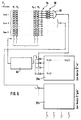
- FIG. 6 shows an illustration of a simple technical possibility for a circuit arrangement, with which the scanning process can be implemented in an uncomplicated manner.
- N z sensor rows 30 after amplification 54 and threshold discrimination 56 are combined by an OR gate 58.
- OR gate 58 Coming from the lens side of the image plane, coming from the left (arrow Y), all columns N 1 - N S are queried in order.
- a pixel As soon as a pixel is discovered, it becomes a zone (Zone 1 - Zone 3) selected look-up table 28a, 28b.
- There will a certain column is activated by the light transmitter, and the Row is through a column advance 60 of the sensor level activated.
- each column of the look-up table 28a or 28b in turn during a light transmitter scan run through.
- every element (x, y) of the look-up table is activated once during a light transmitter scan.
- the value of the look-up table element (x, y) that is in activated at the moment when a point of light is detected is sent to the monitor (not shown).
- This Value (x, y) contains the screen coordinates of a pixel, the color or other vertical identifier assigned to its zone wearing. After a point of light has been discovered, a gate circuit (not shown) blocks the rest of one Sensor level scans to ensure that the closest one is always Object point is detected.
- the look-up tables 28a, 28b are made up of PROMs (programmable Read memory) formed. You will be calibrated on a Rail "burned" firmly connected transmitter and receiver, are therefore no longer changed. They contain that for each sensor level column (according to the look-up table row) and each sending direction (according to the look-up table column) valid screen coordinate pair. These coordinates are calculated, as stated at the beginning, according to the rules of the plane trigonometry, corrected for distortions that partly come from the wide-angle optics of the camera (s), some others, causes to be determined empirically.
- PROMs programmable Read memory
- the invention provides a reversing aid specify that the driver is particularly reliable when reversing Information about the respective spatial arrangement of objects in the rear danger zone relative to the Vehicle supplies.
- the invention Reversing aid the object acquisition and information processing particularly simple, robust, reliable and inexpensive.
Landscapes
- Engineering & Computer Science (AREA)
- Remote Sensing (AREA)
- Physics & Mathematics (AREA)
- Mechanical Engineering (AREA)
- Human Computer Interaction (AREA)
- Radar, Positioning & Navigation (AREA)
- Transportation (AREA)
- Computer Networks & Wireless Communication (AREA)
- Multimedia (AREA)
- Electromagnetism (AREA)
- General Physics & Mathematics (AREA)
- Traffic Control Systems (AREA)
- Optical Radar Systems And Details Thereof (AREA)
- Measurement Of Optical Distance (AREA)
- Length Measuring Devices By Optical Means (AREA)
Applications Claiming Priority (2)
| Application Number | Priority Date | Filing Date | Title |
|---|---|---|---|
| DE19932779A DE19932779A1 (de) | 1999-07-14 | 1999-07-14 | Rückfahrhilfe |
| DE19932779 | 1999-07-14 |
Publications (2)
| Publication Number | Publication Date |
|---|---|
| EP1068992A2 true EP1068992A2 (fr) | 2001-01-17 |
| EP1068992A3 EP1068992A3 (fr) | 2003-04-23 |
Family
ID=7914662
Family Applications (1)
| Application Number | Title | Priority Date | Filing Date |
|---|---|---|---|
| EP00112221A Withdrawn EP1068992A3 (fr) | 1999-07-14 | 2000-06-07 | Aide pour reculer |
Country Status (4)
| Country | Link |
|---|---|
| US (1) | US6429420B1 (fr) |
| EP (1) | EP1068992A3 (fr) |
| JP (1) | JP2001055101A (fr) |
| DE (1) | DE19932779A1 (fr) |
Cited By (6)
| Publication number | Priority date | Publication date | Assignee | Title |
|---|---|---|---|---|
| EP1122557A3 (fr) * | 2000-02-05 | 2002-01-09 | Valeo Schalter und Sensoren GmbH | Dispositif de surveillance optique de l'environnement d'un véhicule |
| WO2003050562A1 (fr) * | 2001-12-07 | 2003-06-19 | Robert Bosch Gmbh | Procede d'identification d'obstacles pour une automobile, avec au moins trois detecteurs de distance pour detecter l'extension laterale d'un objet |
| EP1296412A3 (fr) * | 2001-09-21 | 2004-01-07 | Bayerische Motoren Werke Aktiengesellschaft | Dispositif d'aide de parcage pour des véhicules automobiles |
| EP1628141A1 (fr) * | 2004-08-17 | 2006-02-22 | Robert Bosch Gmbh | Procède de triangulation ayant des diodes laser et une caméra pour determiner la distance pour les applications arret-demarrage des véhicules automobiles |
| US7079017B2 (en) | 2001-04-23 | 2006-07-18 | Lang-Mekra North America, Llc | Warning device in motor vehicles |
| EP3401165A1 (fr) * | 2017-05-12 | 2018-11-14 | RENAULT s.a.s. | Aide à la conduite en phase de recul permettant l'ouverture sans risqué d'un ouvrant arrière |
Families Citing this family (35)
| Publication number | Priority date | Publication date | Assignee | Title |
|---|---|---|---|---|
| US6957177B1 (en) * | 1999-12-10 | 2005-10-18 | Microsoft Corporation | Geometric model database for use in ubiquitous computing |
| DE10059313A1 (de) | 2000-11-29 | 2002-06-13 | Bosch Gmbh Robert | Anordnung und Verfahren zur Überwachung des Umfelds eines Fahrzeugs |
| DE10109665B4 (de) * | 2001-02-28 | 2017-11-09 | Volkswagen Ag | Verfahren zur Darstellung der Umgebung eines Kraftfahrzeugs |
| DE10127204A1 (de) | 2001-06-05 | 2003-03-20 | Ibeo Automobile Sensor Gmbh | Erfassungsverfahren und - vorrichtung |
| DE10151965A1 (de) * | 2001-10-20 | 2003-05-08 | Valeo Schalter & Sensoren Gmbh | Verfahren zum Betreiben eines Nahbereichserkennungssystems und Nahbereichserkennungssystem |
| DE10210301A1 (de) * | 2002-03-08 | 2003-09-18 | Valeo Schalter & Sensoren Gmbh | Verfahren und System zur Erfassung von Gegenständen im Nahbereich eines Fahrzeuges |
| DE10243620A1 (de) * | 2002-09-19 | 2004-04-01 | Valeo Schalter Und Sensoren Gmbh | Verfahren zur Bildverarbeitung der von einem System zur Umfelderfassung eines Fahrzeuges erfassten optischen Signale und System zur Umfelderfassung eines Fahrzeuges |
| DE10312548B3 (de) * | 2003-03-21 | 2004-05-19 | Audi Ag | Kraftfahrzeug |
| US6995662B2 (en) * | 2003-05-06 | 2006-02-07 | Wortsmith Joe W | Vehicle positioning apparatus |
| DE10326190A1 (de) * | 2003-06-06 | 2004-12-30 | Daimlerchrysler Ag | Vorrichtung und Verfahren zur Ermittlung einer räumlichen Ausrichtung eines Auflegers oder Anhängers |
| DE102004001555B4 (de) * | 2004-01-10 | 2018-02-15 | Robert Bosch Gmbh | Verfahren und System für die Spurführung eines Fahrzeugs |
| US7986731B2 (en) | 2004-02-06 | 2011-07-26 | Apple Inc. | H.264/AVC coder incorporating rate and quality controller |
| US7492820B2 (en) | 2004-02-06 | 2009-02-17 | Apple Inc. | Rate control for video coder employing adaptive linear regression bits modeling |
| DE102004007553A1 (de) * | 2004-02-17 | 2005-09-01 | Daimlerchrysler Ag | Erfassungsvorrichtung und Sicherheitssystem für ein Kraftfahrzeug |
| DE102004014357A1 (de) * | 2004-03-24 | 2005-10-13 | Daimlerchrysler Ag | Verfahren und Vorrichtung zur Unterstützung des Fahrers bei Fahrmanövern, insbesondere Einparkmanövern |
| DE102004047121B4 (de) * | 2004-09-27 | 2012-12-06 | Andreas Stopp | Verfahren zum Betreiben verstellbarer Sensoren zur Hinderniserkennung durch ein Kraftfahrzeug |
| JP2006160193A (ja) * | 2004-12-10 | 2006-06-22 | Alpine Electronics Inc | 車両運転支援装置 |
| DE102006007150A1 (de) * | 2005-08-05 | 2007-02-08 | Volkswagen Ag | Verfahren und Vorrichtung zur Parklückenvermessung |
| TW200722311A (en) * | 2005-12-06 | 2007-06-16 | Kinpo Elect Inc | Parking guidance apparatus and method |
| KR100696392B1 (ko) * | 2005-12-07 | 2007-03-19 | 주식회사단해 | 차량 외곽 모니터링 시스템 및 그 방법 |
| US7375621B1 (en) | 2007-06-05 | 2008-05-20 | Hines Stephen P | Vehicle parking apparatus |
| DE102007062159A1 (de) * | 2007-12-21 | 2009-06-25 | Hella Kgaa Hueck & Co. | Radarsensoranordnung |
| US8264377B2 (en) | 2009-03-02 | 2012-09-11 | Griffith Gregory M | Aircraft collision avoidance system |
| KR200463011Y1 (ko) * | 2010-01-07 | 2012-10-16 | 쓰리에이치비젼주식회사 | 주차 가이드 라인 장치 |
| DE102010034853A1 (de) * | 2010-08-18 | 2012-02-23 | Gm Global Technology Operations Llc (N.D.Ges.D. Staates Delaware) | Kraftfahrzeug mit Digitalprojektoren |
| JP5811189B2 (ja) * | 2011-12-28 | 2015-11-11 | トヨタ自動車株式会社 | 障害物判定装置 |
| DE102012201929A1 (de) * | 2012-02-09 | 2013-08-14 | Bayerische Motoren Werke Aktiengesellschaft | Verfahren und Vorrichtung zum Erkennen einer Gefahrensituation für ein Fahrzeugteil eines Fahrzeugs |
| DE102015008042B3 (de) * | 2015-06-23 | 2016-12-15 | Mekra Lang Gmbh & Co. Kg | Anzeigeeinrichtung für Fahrzeuge, insbesondere Nutzfahrzeuge |
| DE102016001202B4 (de) * | 2016-02-03 | 2021-07-08 | Audi Ag | Kraftfahrzeug |
| DE102016001204B4 (de) * | 2016-02-03 | 2021-07-08 | Audi Ag | Kraftfahrzeug |
| DE102016001201B4 (de) * | 2016-02-03 | 2021-07-08 | Audi Ag | Kraftfahrzeug |
| DE102016001207B4 (de) * | 2016-02-03 | 2021-07-08 | Audi Ag | Kraftfahrzeug |
| US10486742B2 (en) * | 2016-08-01 | 2019-11-26 | Magna Electronics Inc. | Parking assist system using light projections |
| US11076109B2 (en) * | 2019-09-16 | 2021-07-27 | Tusimple, Inc. | Sensor layout for autonomous vehicles |
| US11682313B2 (en) | 2021-03-17 | 2023-06-20 | Gregory M. Griffith | Sensor assembly for use in association with aircraft collision avoidance system and method of using the same |
Citations (2)
| Publication number | Priority date | Publication date | Assignee | Title |
|---|---|---|---|---|
| DE8717494U1 (de) | 1987-09-15 | 1989-02-09 | Kolbatz, Klaus-Peter, 1000 Berlin | Einparkhilfe für Kraftfahrzeuge |
| DE4303066C2 (de) | 1993-02-03 | 1994-08-11 | Steinbacher Peter Dipl Ing Fh | Parkhilfe für Kraftfahrzeuge |
Family Cites Families (13)
| Publication number | Priority date | Publication date | Assignee | Title |
|---|---|---|---|---|
| US5373482A (en) * | 1990-02-26 | 1994-12-13 | Trend Tec Inc. | Distance measuring system arranged to limit false indications of distance measurements |
| GB9011793D0 (en) * | 1990-05-25 | 1990-07-18 | Buckley Steven D | Caravan reversing aid |
| CH680690A5 (fr) * | 1991-01-24 | 1992-10-15 | Peter Werner Sprenger | |
| US5235316A (en) * | 1991-12-20 | 1993-08-10 | Qualizza Gregory K | Vehicle collision avoidance system |
| JP3052563B2 (ja) | 1992-04-24 | 2000-06-12 | 株式会社デンソー | 車両の目標位置誘導装置 |
| DE4239061A1 (de) * | 1992-11-20 | 1994-05-26 | Rudolf De Wall | Warngerät vor Hindernissen und Gegenständen im Rückwärtsfahrbereich von Lastkraftwagen, Bussen oder ähnlichen Fahrzeugen |
| JP3212218B2 (ja) * | 1994-05-26 | 2001-09-25 | 三菱電機株式会社 | 車両用障害物検出装置 |
| JPH08122060A (ja) | 1994-10-21 | 1996-05-17 | Mitsubishi Electric Corp | 車両周辺監視システム |
| JPH08210821A (ja) | 1995-02-03 | 1996-08-20 | Toyota Motor Corp | 対象物測定装置 |
| DE19603267A1 (de) * | 1996-01-30 | 1997-07-31 | Bosch Gmbh Robert | Vorrichtung zur Abstands- und/oder Positionsbestimmung |
| GB2328819A (en) * | 1997-08-30 | 1999-03-03 | Ford Motor Co | Antenna cluster for vehicle collision warning system |
| DE19756063C1 (de) * | 1997-12-17 | 1998-12-17 | Daimler Benz Ag | Anzeige für eine elektronische Rückfahrhilfe |
| GB2351055A (en) * | 1999-06-16 | 2000-12-20 | Albert Franks | Vehicle reversing aid |
-
1999
- 1999-07-14 DE DE19932779A patent/DE19932779A1/de not_active Withdrawn
-
2000
- 2000-06-07 EP EP00112221A patent/EP1068992A3/fr not_active Withdrawn
- 2000-06-30 US US09/607,476 patent/US6429420B1/en not_active Expired - Fee Related
- 2000-07-07 JP JP2000206585A patent/JP2001055101A/ja active Pending
Patent Citations (2)
| Publication number | Priority date | Publication date | Assignee | Title |
|---|---|---|---|---|
| DE8717494U1 (de) | 1987-09-15 | 1989-02-09 | Kolbatz, Klaus-Peter, 1000 Berlin | Einparkhilfe für Kraftfahrzeuge |
| DE4303066C2 (de) | 1993-02-03 | 1994-08-11 | Steinbacher Peter Dipl Ing Fh | Parkhilfe für Kraftfahrzeuge |
Cited By (9)
| Publication number | Priority date | Publication date | Assignee | Title |
|---|---|---|---|---|
| EP1122557A3 (fr) * | 2000-02-05 | 2002-01-09 | Valeo Schalter und Sensoren GmbH | Dispositif de surveillance optique de l'environnement d'un véhicule |
| US7079017B2 (en) | 2001-04-23 | 2006-07-18 | Lang-Mekra North America, Llc | Warning device in motor vehicles |
| EP1296412A3 (fr) * | 2001-09-21 | 2004-01-07 | Bayerische Motoren Werke Aktiengesellschaft | Dispositif d'aide de parcage pour des véhicules automobiles |
| US6819284B2 (en) | 2001-09-21 | 2004-11-16 | Bayerische Motoren Werke Aktiengesellschaft | System for assisting the parking of motor vehicles in parking spaces |
| WO2003050562A1 (fr) * | 2001-12-07 | 2003-06-19 | Robert Bosch Gmbh | Procede d'identification d'obstacles pour une automobile, avec au moins trois detecteurs de distance pour detecter l'extension laterale d'un objet |
| US6947841B2 (en) | 2001-12-07 | 2005-09-20 | Robert Bosch Gmbh | Method for identifying obstacles for a motor vehicle, using at least three distance sensors for identifying the lateral extension of an object |
| EP1628141A1 (fr) * | 2004-08-17 | 2006-02-22 | Robert Bosch Gmbh | Procède de triangulation ayant des diodes laser et une caméra pour determiner la distance pour les applications arret-demarrage des véhicules automobiles |
| EP3401165A1 (fr) * | 2017-05-12 | 2018-11-14 | RENAULT s.a.s. | Aide à la conduite en phase de recul permettant l'ouverture sans risqué d'un ouvrant arrière |
| FR3066157A1 (fr) * | 2017-05-12 | 2018-11-16 | Renault S.A.S. | Aide a la conduite en phase de recul permettant l'ouverture sans risque d'un ouvrant arriere |
Also Published As
| Publication number | Publication date |
|---|---|
| DE19932779A1 (de) | 2001-01-25 |
| US6429420B1 (en) | 2002-08-06 |
| EP1068992A3 (fr) | 2003-04-23 |
| JP2001055101A (ja) | 2001-02-27 |
Similar Documents
| Publication | Publication Date | Title |
|---|---|---|
| EP1068992A2 (fr) | Aide pour reculer | |
| DE102015213701B4 (de) | Sensorsystem für ein Fahrzeug zum Erkennen von Brücken oder Tunneleinfahrten | |
| EP1407293B1 (fr) | Procede et dispositif d'acquisition | |
| DE69306436T3 (de) | Vorrichtung zur Detektion eines Hindernisses für Kraftfahrzeuge | |
| DE10114932B4 (de) | Dreidimensionale Umfelderfassung | |
| DE102008004633A1 (de) | Verfahren und Vorrichtung zur Erkennung und/oder Vermessung einer Parklücke | |
| DE102018108751B4 (de) | Verfahren, System und Vorrichtung zum Erhalten von 3D-Information von Objekten | |
| DE102013010010B4 (de) | Verfahren zum Betrieb eines Fahrerassistenzsystems zum Rangieren und/oder Parken | |
| DE102009007408B4 (de) | Vorrichtung zur Umfelderfassung eines Kraftfahrzeugs | |
| WO2019110206A1 (fr) | Système lidar de perception de l'environnement et procédé pour faire fonctionner un système lidar | |
| EP3545338B1 (fr) | Dispositif de réception pour un dispositif de détection optique, dispositif de détection et système d'aide à la conduite | |
| DE102011017707A1 (de) | Verfahren und Vorrichtung zur Erkennung von einem Objekt in einer Umgebung einer Kamera | |
| WO2023247302A1 (fr) | Procédé de détermination d'au moins une fonction de correction pour un système lidar, système lidar, véhicule comprenant au moins un système lidar et système de mesure | |
| EP2013642A1 (fr) | Procede et dispositif de prise de vue a distance | |
| WO2021156269A1 (fr) | Système de détection destiné à un véhicule permettant la surveillance d'une zone de surveillance horizontale d'au moins 180° | |
| EP3994482A1 (fr) | Dispositif de mesure optique pour la détermination d'informations d'objet pour des objets dans au moins une zone de surveillance | |
| DE102019128437A1 (de) | Kalibriervorrichtung zur Kalibrierung wenigstens einer optischen Detektionsvorrichtung | |
| DE102024130057A1 (de) | Computerimplementiertes verfahren, elektronisches fahrzeugsystem und computerprogrammprodukt | |
| DE102022202206A1 (de) | LiDAR-System und Verfahren zum Betreiben eines LiDAR-Systems | |
| EP3945339A1 (fr) | Dispositif de détection optique permettant de surveiller au moins une zone de surveillance au niveau d'objets et procédé de fonctionnement d'un dispositif de détection optique | |
| DE102024120324A1 (de) | Verfahren zur kalibrierung eines optischen sensorsystems und optisches sensorsystem | |
| DE102022115277A1 (de) | Verfahren zum Betreiben eines LiDAR-Systems, LiDAR-System und Fahrzeug | |
| DE102024130272A1 (de) | Lidar-System und Verfahren zur Umgebungserfassung | |
| DE102023109215A1 (de) | Verfahren zum Betreiben eines LiDAR-Systems, LiDAR-System, Fahrerassistenzsystem und Fahrzeug | |
| DE102023135584A1 (de) | Verfahren zum Betreiben eines iToF-LiDAR-Systems, bei dem auf Basis von validierten Empfangsgrößen korrigierte Empfangsgrößen ermittelt werden, iToF-LiDAR-System, Fahrerassistenzsystem und Fahrzeug |
Legal Events
| Date | Code | Title | Description |
|---|---|---|---|
| PUAI | Public reference made under article 153(3) epc to a published international application that has entered the european phase |
Free format text: ORIGINAL CODE: 0009012 |
|
| AK | Designated contracting states |
Kind code of ref document: A2 Designated state(s): AT BE CH CY DE DK ES FI FR GB GR IE IT LI LU MC NL PT SE |
|
| AX | Request for extension of the european patent |
Free format text: AL;LT;LV;MK;RO;SI |
|
| PUAL | Search report despatched |
Free format text: ORIGINAL CODE: 0009013 |
|
| AK | Designated contracting states |
Designated state(s): AT BE CH CY DE DK ES FI FR GB GR IE IT LI LU MC NL PT SE |
|
| AX | Request for extension of the european patent |
Extension state: AL LT LV MK RO SI |
|
| RIC1 | Information provided on ipc code assigned before grant |
Ipc: 7G 01S 17/93 B Ipc: 7B 60Q 1/48 A |
|
| STAA | Information on the status of an ep patent application or granted ep patent |
Free format text: STATUS: THE APPLICATION HAS BEEN WITHDRAWN |
|
| 18W | Application withdrawn |
Effective date: 20030826 |