EP1069057A1 - Receptacle for compostable materials - Google Patents
Receptacle for compostable materials Download PDFInfo
- Publication number
- EP1069057A1 EP1069057A1 EP20000114614 EP00114614A EP1069057A1 EP 1069057 A1 EP1069057 A1 EP 1069057A1 EP 20000114614 EP20000114614 EP 20000114614 EP 00114614 A EP00114614 A EP 00114614A EP 1069057 A1 EP1069057 A1 EP 1069057A1
- Authority
- EP
- European Patent Office
- Prior art keywords
- container
- grate
- container according
- hose
- outside
- Prior art date
- Legal status (The legal status is an assumption and is not a legal conclusion. Google has not performed a legal analysis and makes no representation as to the accuracy of the status listed.)
- Granted
Links
- 239000000463 material Substances 0.000 title claims description 8
- XLYOFNOQVPJJNP-UHFFFAOYSA-N water Substances O XLYOFNOQVPJJNP-UHFFFAOYSA-N 0.000 claims abstract description 11
- 238000009423 ventilation Methods 0.000 claims abstract description 10
- 239000007788 liquid Substances 0.000 claims description 16
- 239000002184 metal Substances 0.000 claims description 5
- 239000012780 transparent material Substances 0.000 claims 1
- 238000009264 composting Methods 0.000 abstract description 10
- 238000000034 method Methods 0.000 abstract description 8
- JEIPFZHSYJVQDO-UHFFFAOYSA-N iron(III) oxide Inorganic materials O=[Fe]O[Fe]=O JEIPFZHSYJVQDO-UHFFFAOYSA-N 0.000 description 5
- 239000010813 municipal solid waste Substances 0.000 description 3
- 239000002361 compost Substances 0.000 description 2
- 230000015572 biosynthetic process Effects 0.000 description 1
- 238000009833 condensation Methods 0.000 description 1
- 230000005494 condensation Effects 0.000 description 1
- 238000009795 derivation Methods 0.000 description 1
- 235000013399 edible fruits Nutrition 0.000 description 1
- 230000000694 effects Effects 0.000 description 1
- 230000004720 fertilization Effects 0.000 description 1
- 239000003337 fertilizer Substances 0.000 description 1
- 239000012530 fluid Substances 0.000 description 1
- 239000010921 garden waste Substances 0.000 description 1
- 238000005259 measurement Methods 0.000 description 1
- 230000009965 odorless effect Effects 0.000 description 1
- 239000011368 organic material Substances 0.000 description 1
- 230000000630 rising effect Effects 0.000 description 1
- 238000007789 sealing Methods 0.000 description 1
- 238000007493 shaping process Methods 0.000 description 1
- 235000013311 vegetables Nutrition 0.000 description 1
Images
Classifications
-
- B—PERFORMING OPERATIONS; TRANSPORTING
- B65—CONVEYING; PACKING; STORING; HANDLING THIN OR FILAMENTARY MATERIAL
- B65F—GATHERING OR REMOVAL OF DOMESTIC OR LIKE REFUSE
- B65F1/00—Refuse receptacles; Accessories therefor
- B65F1/14—Other constructional features; Accessories
- B65F1/16—Lids or covers
-
- C—CHEMISTRY; METALLURGY
- C05—FERTILISERS; MANUFACTURE THEREOF
- C05F—ORGANIC FERTILISERS NOT COVERED BY SUBCLASSES C05B, C05C, e.g. FERTILISERS FROM WASTE OR REFUSE
- C05F17/00—Preparation of fertilisers characterised by biological or biochemical treatment steps, e.g. composting or fermentation
- C05F17/90—Apparatus therefor
- C05F17/907—Small-scale devices without mechanical means for feeding or discharging material, e.g. garden compost bins
-
- C—CHEMISTRY; METALLURGY
- C05—FERTILISERS; MANUFACTURE THEREOF
- C05F—ORGANIC FERTILISERS NOT COVERED BY SUBCLASSES C05B, C05C, e.g. FERTILISERS FROM WASTE OR REFUSE
- C05F17/00—Preparation of fertilisers characterised by biological or biochemical treatment steps, e.g. composting or fermentation
- C05F17/90—Apparatus therefor
- C05F17/964—Constructional parts, e.g. floors, covers or doors
- C05F17/971—Constructional parts, e.g. floors, covers or doors for feeding or discharging materials to be treated; for feeding or discharging other material
- C05F17/986—Constructional parts, e.g. floors, covers or doors for feeding or discharging materials to be treated; for feeding or discharging other material the other material being liquid
-
- B—PERFORMING OPERATIONS; TRANSPORTING
- B65—CONVEYING; PACKING; STORING; HANDLING THIN OR FILAMENTARY MATERIAL
- B65F—GATHERING OR REMOVAL OF DOMESTIC OR LIKE REFUSE
- B65F1/00—Refuse receptacles; Accessories therefor
- B65F1/14—Other constructional features; Accessories
- B65F2001/1489—Refuse receptacles adapted or modified for gathering compostable domestic refuse
-
- B—PERFORMING OPERATIONS; TRANSPORTING
- B65—CONVEYING; PACKING; STORING; HANDLING THIN OR FILAMENTARY MATERIAL
- B65F—GATHERING OR REMOVAL OF DOMESTIC OR LIKE REFUSE
- B65F2210/00—Equipment of refuse receptacles
- B65F2210/181—Ventilating means, e.g. holes
-
- Y—GENERAL TAGGING OF NEW TECHNOLOGICAL DEVELOPMENTS; GENERAL TAGGING OF CROSS-SECTIONAL TECHNOLOGIES SPANNING OVER SEVERAL SECTIONS OF THE IPC; TECHNICAL SUBJECTS COVERED BY FORMER USPC CROSS-REFERENCE ART COLLECTIONS [XRACs] AND DIGESTS
- Y02—TECHNOLOGIES OR APPLICATIONS FOR MITIGATION OR ADAPTATION AGAINST CLIMATE CHANGE
- Y02P—CLIMATE CHANGE MITIGATION TECHNOLOGIES IN THE PRODUCTION OR PROCESSING OF GOODS
- Y02P20/00—Technologies relating to chemical industry
- Y02P20/141—Feedstock
- Y02P20/145—Feedstock the feedstock being materials of biological origin
-
- Y—GENERAL TAGGING OF NEW TECHNOLOGICAL DEVELOPMENTS; GENERAL TAGGING OF CROSS-SECTIONAL TECHNOLOGIES SPANNING OVER SEVERAL SECTIONS OF THE IPC; TECHNICAL SUBJECTS COVERED BY FORMER USPC CROSS-REFERENCE ART COLLECTIONS [XRACs] AND DIGESTS
- Y02—TECHNOLOGIES OR APPLICATIONS FOR MITIGATION OR ADAPTATION AGAINST CLIMATE CHANGE
- Y02W—CLIMATE CHANGE MITIGATION TECHNOLOGIES RELATED TO WASTEWATER TREATMENT OR WASTE MANAGEMENT
- Y02W30/00—Technologies for solid waste management
- Y02W30/40—Bio-organic fraction processing; Production of fertilisers from the organic fraction of waste or refuse
Definitions
- the invention relates to a container according to the preamble of the main claim.
- a generic container is known from FR 27 18 435 A.
- This known container like the container, is on which the invention relates to as a standard container for Household application running and this container can be on be emptied in the usual way by a delivery service, for what Household garbage trucks are used, which are equipped with lifting equipment that can attack at the top of the container.
- the generic container is intended for composting organic material such as vegetables, fruit and garden waste or Like. Be used. Via air supply and air discharge openings air circulation can be achieved, which is necessary for the good course of the composting process is necessary. A lockable Opening in the area of the bottom of the container makes it possible to take out the compost.
- DE 44 27 729 discloses a connecting device with at least one two connections, the parallel and at the same time to the corresponding connections of a biocontainer can be connected with a high sealing effect can. From this reference it is known to the drain opening connect a hose to a biocontainer, So instead of or in addition to that in the generic Literature described drain cock provided can be. With such a hose, the hygienic Reasons also provided with a closure member must be, but is not controllable how high the water level in the collection container of the biocontainer.
- the amount of moisture that is released depends heavily on the amount and the type of material to be composted and the prevailing Temperatures. It is therefore not always clear when the moisture needs to be drained and the user can forget the drainage of moisture so that the Composting process by the rising within the container Liquid is interrupted.
- the drain opening is for the Moisture formed as a tap, its location and thus whose operation is unwieldy.
- the present invention has for its object the generic To improve the container so that the Liquid level in the container is controllable and draining the liquid is facilitated and the formation of the Rust to a good discharge in the lower area of the compostable liquid.
- the Drain opening known from the prior art to the outside there is a flexible hose that is transparent and that can be raised and clamped outside the container.
- This hose must of course be open at its upper end to be with the one located in the lower area of the container Fluid level to a communicating tube create.
- the container with a Hollow pin equipped by the upper end of the Hose can be overlapped, so that on the one hand the Hose is set, on the other hand, the hose opening after is open at the top and continues to ensure that itself then when the liquid level in the hose up to the top the liquid has not risen to the outside can, but is returned to the container. This is just a security measure that contaminates the Prevents the environment of the container, but the composting process would be interrupted.
- An essential feature of the invention is that the bottom of the lid closing the container so inclined or is designed so that the collecting condensation is discharged to the outside of the container. While in normal organic bins one strives to be at the bottom the lid collecting moisture into the container and return to the material in the container, In the present case, the aim is to get the moisture out lead away, this condensed water usually is odorless, making it easy to drain off to the outside of the container appears possible.
- rust is preferably made of metal trained and a metal plate is used, which with Flow openings are provided, which face downwards Connects each ring flange, d. H. these flow openings are punched out from top to bottom and the amount of material is formed into a ring flange. It turned out that with such an arrangement the drainage of the liquid done much better than if the metal plate only is provided with simple flow openings.
- the rust is preferably profiled and based on the container bottom arranged supports from and still preferably on shoulders molded from the wall of the container and is either on the shoulders and / or on the supports set using appropriate tools so that when dumping of the container, for example in a garbage truck, the rust is secured in position in the container.
- the ventilation openings are arranged at the device according to the invention is designed as ventilation pipes, that cross the container, these pipes with Air passage openings are provided, which makes it possible sufficient over the entire lower side of the container Ensure air supply.
- These pipes can be made of metal or also consist of plastic.
- the one preferably provided in the rear wall of the container The removal opening is closed by a slide which can be lifted upwards so that the removal opening is released.
- a slide has opposite a conventional flap has the advantage that joints are avoided and that only a partial opening of the actual removal opening depending on the flowability of the compost formed can be adjusted.
- a container 1 which has a lid 2 and a grate 3 in the lower region, wherein the container is closed at the bottom by the container bottom 4 is.
- the container is made of a moldable material, for example plastic.
- ventilation openings in the lower area of the container 5 indicated, with a plurality of such ventilation openings can be provided, which is provided below the grate 3 become. It could also be above the grate Ventilation openings are provided in the lower area of the container his.
- the container bottom 4 is with a Drain opening 7 equipped, the bottom of the container, as from the drawing is recognizable, designed so that the collecting Liquid is guided to this drain opening 7.
- the drawing shows the inclination of the container bottom 4, which leads from the front wall of the container to the rear, whereby continue to be roof-shaped container bottom can, so that the liquid from the side walls Drain opening 7 is performed, the drain opening 7 is not in middle part of the container bottom 4 can be formed, but for example in the area of a side wall, so that only a cross slope of the container bottom is required.
- the back of the container is referred to as side wall 9 and has a removal opening 8 through a slide 16 is closable, which can be moved upwards can, so that a partial opening of the large removal opening 8 becomes possible.
- a transparent hose 10 closes on which led upwards on the side wall 9 to a hollow pin 19 leads from a shoulder recess of the side wall 9 is formed.
- the hose mouth can be on this Hollow pin 19 are pushed on and is thereby determined but is open in terms of ventilation, so that a communicating Pipe system with the area of the tank bottom below the grate 3 is reached.
- Grid 3 through openings 12 are provided, which face downwards open into an annular flange 14 which either - as in the middle Part of the grate shown as an embodiment - rectilinear, i.e. cylindrical or - as with the two outer ones Flow openings 12 shown - down again broaden out.
- This type of passage opening design improves the discharge of the accumulated on the grate Water.
- the grate is - as shown in Fig. 2 - profiled to thus to have the required load capacity, whereby in the 2, which shows a section through the grate which represents line AA in FIG. 2, is curved upwards, so that a good derivation of the accumulating on the profiles Water is accessible to the side.
- the pressure in the hose 10 always corresponds to the pressure in the container 1, so that an undisturbed function based on the principle of the communicating tubes is reached.
- the compostable material comes in the lower area in contact with the liquid, causing the composting process comes to a standstill.
- the container 1 can simply be offered for emptying, then after filling the container 1 and again in motion bring the composting process back to work can be.
- the container body is like this trained that by shaping the sufficient strength of the container is achieved, on the other hand, a good emptying of the Container in case of garbage truck emptying is ensured.
- Condensed water can also be provided that at the Hose, d. H. a suction pump or. Like. Can be connected so that the water in the garden specifically Fertilization can be used.
Landscapes
- Chemical & Material Sciences (AREA)
- Engineering & Computer Science (AREA)
- General Chemical & Material Sciences (AREA)
- Microbiology (AREA)
- Health & Medical Sciences (AREA)
- Biochemistry (AREA)
- Biotechnology (AREA)
- Chemical Kinetics & Catalysis (AREA)
- Organic Chemistry (AREA)
- Life Sciences & Earth Sciences (AREA)
- Molecular Biology (AREA)
- Mechanical Engineering (AREA)
- Fertilizers (AREA)
- Processing Of Solid Wastes (AREA)
- Glass Compositions (AREA)
- Packging For Living Organisms, Food Or Medicinal Products That Are Sensitive To Environmental Conditiond (AREA)
Abstract
Description
Die Erfindung bezieht sich auf einen Behälter gemäß dem Oberbegriff des Hauptanspruches.The invention relates to a container according to the preamble of the main claim.
Ein gattungsbildender Behälter ist aus der FR 27 18 435 A bekannt. Dieser bekannte Behälter ist ebenso wie der Behälter, auf den sich die Erfindung bezieht, als ein Standardcontainer für Haushaltsanwendung ausgeführt und dieser Container kann auf übliche Weise durch einen Abfuhrdienst entleert werden, wozu Hausmüllwagen eingesetzt werden, die mit Hebemitteln ausgerüstet sind, die am Oberrand des Containers angreifen können.A generic container is known from FR 27 18 435 A. This known container, like the container, is on which the invention relates to as a standard container for Household application running and this container can be on be emptied in the usual way by a delivery service, for what Household garbage trucks are used, which are equipped with lifting equipment that can attack at the top of the container.
Der gattungsbildende Container soll für das Kompostieren von organischem Material, wie Gemüse, Obst und Gartenabfall od. dgl. verwendet werden. Über Luftzufuhr- und Luftabfuhröffnungen kann eine Luftzirkulation bewerkstelligt werden, die für den guten Verlauf des Kompostiervorganges notwendig ist. Eine verschließbare Öffnung im Bereich der Unterseite des Behälters macht es möglich, den Kompost herauszunehmen.The generic container is intended for composting organic material such as vegetables, fruit and garden waste or Like. Be used. Via air supply and air discharge openings air circulation can be achieved, which is necessary for the good course of the composting process is necessary. A lockable Opening in the area of the bottom of the container makes it possible to take out the compost.
Beim Kompostierprozeß werden erhebliche Mengen an Feuchtigkeit frei. Diese Feuchtigkeit sammelt sich unter dem durchlässigen Rost des Containers und muß von Zeit zu Zeit abgelassen werden, da bei einem hohen Feuchtigkeitsniveau der Kompostiervorgang zum Stillstand kommen würde. In dem gattungsbildenden Container ist deshalb ein Ablaßhahn vorgesehen, über den sodann die Feuchtigkeit abgelassen werden kann.During the composting process, considerable amounts of moisture are generated free. This moisture collects under the permeable Rust of the container and must be drained from time to time because the composting process takes place at a high level of moisture would come to a standstill. In the generic Container is therefore provided with a drain tap then the moisture can be drained off.
Aus der DE 44 27 729 ist eine Anschließvorrichtung mit mindestens zwei Anschlüssen bekanntgeworden, die parallel und gleichzeitig an die entsprechenden Anschlüsse eines Biocontainers mit hoher Abdichtungswirkung angeschlossen werden kann. Aus dieser Literaturstelle ist es bekannt, an die Ablaßöffnung eines Biocontainers einen Schlauch anzuschließen, der also anstelle oder zusätzlich zu dem in der gattungsbildenden Literaturstelle beschriebenen Ablaßhahn vorgesehen werden kann. Mit einem solchen Schlauch, der aus hygienischen Gründen ebenfalls mit einem Verschlußorgan versehen sein muß, ist aber nicht kontrollierbar, wie hoch der Wasserstand im Auffangbehälter des Biocontainers ist.DE 44 27 729 discloses a connecting device with at least one two connections, the parallel and at the same time to the corresponding connections of a biocontainer can be connected with a high sealing effect can. From this reference it is known to the drain opening connect a hose to a biocontainer, So instead of or in addition to that in the generic Literature described drain cock provided can be. With such a hose, the hygienic Reasons also provided with a closure member must be, but is not controllable how high the water level in the collection container of the biocontainer.
Die Menge Feuchtigkeit, die frei wird, hängt stark von der Menge und der Art des zu kompostierenden Materials und den herrschenden Temperaturen ab. Es ist deshalb nicht immer klar, wann die Feuchtigkeit abgelassen werden muß, und der Benutzer kann das Ablassen der Feuchtigkeit vergessen, so daß der Kompostiervorgang durch die innerhalb des Behälters ansteigende Flüssigkeit unterbrochen wird.The amount of moisture that is released depends heavily on the amount and the type of material to be composted and the prevailing Temperatures. It is therefore not always clear when the moisture needs to be drained and the user can forget the drainage of moisture so that the Composting process by the rising within the container Liquid is interrupted.
Bei dem gattungsbildenden Behälter ist die Ablaßöffnung für die Feuchtigkeit als Zapfhahn ausgebildet, dessen Lage und damit dessen Betätigung unhandlich ist.In the generic container, the drain opening is for the Moisture formed as a tap, its location and thus whose operation is unwieldy.
Der vorliegenden Erfindung liegt die Aufgabe zugrunde, den gattungsbildenden Behälter dahingehend zu verbessern, daß der Flüssigkeitsstand im Behälter kontrollierbar ist und das Ablassen der Flüssigkeit erleichtert wird sowie die Ausbildung des Rostes zu einer guten Abführung der sich im unteren Bereich des kompostierbaren Materials befindenden Flüssigkeit beiträgt. The present invention has for its object the generic To improve the container so that the Liquid level in the container is controllable and draining the liquid is facilitated and the formation of the Rust to a good discharge in the lower area of the compostable liquid.
Diese der Erfindung zugrundeliegende Aufgabe wird durch die Lehre des Hauptanspruches gelöst.This object of the invention is achieved by Teaching of the main claim solved.
Vorteilhafte Ausgestaltungen sind in den Unteransprüchen erläutert.Advantageous configurations are explained in the subclaims.
Mit anderen Worten ausgedrückt wird vorgeschlagen, daß an die aus dem Stand der Technik bekannte Ablaßöffnung nach außen hin ein flexibler Schlauch anschließt, der durchsichtig ist und der außerhalb des Behälters hochführbar und festklemmbar ist. Dieser Schlauch muß natürlich an seinem oberen Ende offen sein, um somit mit dem im unteren Bereich des Behälters befindlichen Flüssigkeitsstand eine kommunizierende Röhre zu schaffen. Vorzugsweise wird dabei an der Seitenwand des Behälters, an der sich der Schlauch befindet, der Behälter mit einem Hohlzapfen ausgerüstet, der von dem oberen Ende des Schlauches übergriffen werden kann, so daß einerseits der Schlauch festgelegt ist, andererseits die Schlauchöffnung nach oben hin offen ist und weiterhin sichergestellt ist, daß selbst dann, wenn der Flüssigkeitsspiegel im Schlauch bis oben hin angestiegen ist, die Flüssigkeit nicht nach außen austreten kann, sondern in den Behälter zurückgeleitet wird. Dies ist lediglich eine Sicherheitsmaßnahme, die ein Verschmutzen der Umgebung des Behälters verhindert, wobei aber der Kompostiervorgang unterbrochen werden würde.In other words, it is proposed that the Drain opening known from the prior art to the outside there is a flexible hose that is transparent and that can be raised and clamped outside the container. This hose must of course be open at its upper end to be with the one located in the lower area of the container Fluid level to a communicating tube create. Preferably, on the side wall of the container, where the hose is located, the container with a Hollow pin equipped by the upper end of the Hose can be overlapped, so that on the one hand the Hose is set, on the other hand, the hose opening after is open at the top and continues to ensure that itself then when the liquid level in the hose up to the top the liquid has not risen to the outside can, but is returned to the container. This is just a security measure that contaminates the Prevents the environment of the container, but the composting process would be interrupted.
Ein wesentliches Merkmal der Erfindung ist darin zu sehen, daß die Unterseite des den Behälter abschließenden Deckels so geneigt bzw. so ausgebildet ist, daß das sich sammelnde Kondenswasser zur Außenseite des Behälters abgeleitet wird. Während in normalen Biotonnen man bestrebt ist, die sich an der Unterseite des Deckels sammelnde Feuchtigkeit in den Behälter und in das sich im Behälter befindliche Material zurückzuführen, wird im vorliegenden Fall angestrebt, die Feuchtigkeit nach außen hin abzuführen, wobei dieses Kondenswasser üblicherweise geruchsfrei ist, so daß ein einfaches Ableiten zur Außenseite des Behälters möglich erscheint.An essential feature of the invention is that the bottom of the lid closing the container so inclined or is designed so that the collecting condensation is discharged to the outside of the container. While in normal organic bins one strives to be at the bottom the lid collecting moisture into the container and return to the material in the container, In the present case, the aim is to get the moisture out lead away, this condensed water usually is odorless, making it easy to drain off to the outside of the container appears possible.
Der das kompostierbare Material innerhalb des Behälters stützende Rost wird gemäß der Erfindung vorzugsweise aus Metall ausgebildet und eine Metallplatte kommt zum Einsatz, die mit Durchlauföffnungen versehen ist, an die sich nach unten ein Ringflansch jeweils anschließt, d. h. diese Durchlauföffnungen werden von oben nach unten ausgestanzt und die Materialmenge wird zu einem Ringflansch umgeformt. Es hat sich herausgestellt, daß bei einer solchen Anordnung das Ableiten der Flüssigkeit wesentlich besser erfolgt als wenn die Metallplatte lediglich mit einfachen Durchlauföffnungen versehen ist. Der Rost ist vorzugsweise profiliert ausgebildet und stützt sich auf am Behälterboden angeordneten Stützen ab und weiterhin vorzugsweise auf aus der Wandung des Behälters ausgeformten Schultern und ist entweder auf den Schultern und/oder auf den Stützen über entsprechende Hilfsmittel festgelegt, so daß beim Auskippen des Behälters, beispielsweise in ein Müllfahrzeug, der Rost lagegesichert im Behälter angeordnet ist.The one that supports the compostable material within the container According to the invention, rust is preferably made of metal trained and a metal plate is used, which with Flow openings are provided, which face downwards Connects each ring flange, d. H. these flow openings are punched out from top to bottom and the amount of material is formed into a ring flange. It turned out that with such an arrangement the drainage of the liquid done much better than if the metal plate only is provided with simple flow openings. The rust is preferably profiled and based on the container bottom arranged supports from and still preferably on shoulders molded from the wall of the container and is either on the shoulders and / or on the supports set using appropriate tools so that when dumping of the container, for example in a garbage truck, the rust is secured in position in the container.
Die aus dem Stand der Technik bekannten, in der unteren Wand des Behälters angeordneten Belüftungsöffnungen werden bei der erfindungsgemäßen Einrichtung als Belüftungsrohre ausgebildet, die den Behälter durchqueren, wobei diese Rohre mit Luftdurchtrittsöffnungen versehen sind, wodurch es möglich ist, über die ganze untere Seite des Behälters eine ausreichende Luftzufuhr sicherzustellen. Diese Rohre können aus Metall oder auch aus Kunststoff bestehen.Those known from the prior art, in the lower wall the ventilation openings are arranged at the device according to the invention is designed as ventilation pipes, that cross the container, these pipes with Air passage openings are provided, which makes it possible sufficient over the entire lower side of the container Ensure air supply. These pipes can be made of metal or also consist of plastic.
Die vorzugsweise in der Rückwand des Behälters vorgesehene Entnahmeöffnung wird durch einen Schieber verschlossen, der nach oben hin angehoben werden kann, so daß die Entnahmeöffnung freigegeben wird. Ein solcher Schieber hat gegenüber einer üblichen Klappe den Vorteil, daß Gelenke vermieden werden und daß ein nur partielles Öffnen der eigentlichen Entnahmeöffnung je nach der Fließfähigkeit des gebildeten Kompostes eingestellt werden kann.The one preferably provided in the rear wall of the container The removal opening is closed by a slide which can be lifted upwards so that the removal opening is released. Such a slide has opposite a conventional flap has the advantage that joints are avoided and that only a partial opening of the actual removal opening depending on the flowability of the compost formed can be adjusted.
Ein Ausführungsbeispiel der Erfindung wird nachfolgend anhand der Zeichnungen erläutert. Die Zeichnungen zeigen dabei in
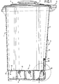
- Fig. 1
- einen Behälter im Schnitt gemäß der Linie 1 - 1 in Fig. 2 und in
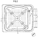
- Fig. 2
- eine Draufsicht in den Behälter bei abgenommenem Behälterdeckel.
- Fig. 1
- a container in section along the line 1 - 1 in Fig. 2 and in
- Fig. 2
- a plan view of the container with the container lid removed.
In den Zeichnungen ist ein Behälter 1 dargestellt, der einen Deckel
2 sowie einen Rost 3 im unteren Bereich aufweist, wobei
nach unten hin der Behälter durch den Behälterboden 4 abgeschlossen
ist. In an sich bekannter Weise ist der Behälter aus
einem formbaren Werkstoff, beispielsweise Kunststoff, hergestellt.
Im unteren Bereich des Behälters sind Belüftungsöffnungen
5 angedeutet, wobei eine Vielzahl solcher Belüftungsöffnungen
vorgesehen sein kann, die unterhalb des Rostes 3 vorgesehen
werden. Zusätzlich könnte auch oberhalb des Rostes
im unteren Bereich des Behälters Belüftungsöffnungen vorgesehen
sein. Im Deckel ist eine entsprechende Belüftungsöffnung
6 ausgebildet, so daß die erforderliche und gewünschte
Luftzirkulation erreichbar ist. Der Behälterboden 4 ist mit einer
Ablaßöffnung 7 ausgerüstet, wobei der Behälterboden, wie aus
der Zeichnung erkennbar, so gestaltet ist, daß die sich sammelnde
Flüssigkeit zu dieser Ablaßöffnung 7 hin geführt ist. In
der Zeichnung ist die Neigung des Behälterbodens 4 erkennbar,
die von der Vorderwand des Behälters zur Rückseite führt, wobei
weiterhin der Behälterboden auch dachförmig gestaltet sein
kann, so daß auch von den Seitenwänden her die Flüssigkeit zur
Ablaßöffnung 7 geführt wird, wobei die Ablaßöffnung 7 nicht im
mittleren Teil des Behälterbodens 4 ausgebildet sein kann, sondern
beispielsweise im Bereich einer Seitenwand, so daß dadurch
nur eine Querneigung des Behälterbodens erforderlich ist.
Die Rückseite des Behälters ist als Seitenwand 9 bezeichnet
und weist eine Entnahmeöffnung 8 auf, die durch einen Schieber
16 verschließbar ist, der nach oben hin verschoben werden
kann, so daß dadurch ein partielles Öffnen der großen Entnahmeöffnung
8 möglich wird. An die Ablaßöffnung 7, die als Rohrzapfen
gestaltet ist, schließt sich ein durchsichtiger Schlauch 10
an, der an der Seitenwand 9 nach oben geführt zu einem Hohlzapfen
19 führt, der aus einem Schulterrücksprung der Seitenwand
9 ausgeformt ist. Die Schlauchmündung kann auf diesen
Hohlzapfen 19 aufgeschoben werden und wird dadurch festgelegt,
ist aber lufttechnisch offen, so daß ein kommunizierendes
Röhrensystem mit dem Bereich des Behälterbodens unterhalb
des Rostes 3 erreicht wird.In the drawings, a container 1 is shown, which has a
Im unteren Bereich des Behälters 1 sind Schultern 18 ausgeformt,
auf die sich der Rost 3 auflegt, wobei der Rost weiterhin
durch Stützen 17 abgestützt wird, die sich andererseits auf dem
Behälterboden 4 abstützen. Der Rost 3 kann dabei sowohl auf
den Schultern 18 wie auch auf den Stützen 17 befestigt werden,
wobei auch die Stützen 17 am Behälterboden festlegbar sind, so
daß ein lagesicheres Festlegen des Rostes 3 erreicht wird, unabhängig
in welcher Stellung sich der Behälter 1 befindet. An
der oberen Rückseite des Behälters ist ein Handgriff 11 angeordnet
und die Innenseite des Deckels ist so geneigt, daß
sichergestellt ist, daß sich das an der Unterseite des Deckels
sammelnde Kondenswasser zur Rückseite ab- und nach außen
hingeführt wird.
In dem in seiner Gestaltung deutlicher aus Fig. 2 erkennbaren
Rost 3 sind Durchlauföffnungen 12 vorgesehen, die nach unten
hin in einen Ringflansch 14 münden, der entweder - wie im mittleren
Teil des Rostes als Ausführungsbeispiel dargestellt -
geradlinig, also zylindrisch sind oder - wie bei den beiden äußeren
Durchlauföffnungen 12 dargestellt - sich wieder nach unten
hin verbreitern. Diese Art der Ausbildung der Durchlauföffnung
verbessert die Abführung des sich auf dem Rost sammelnden
Wassers. In the design more clearly recognizable from FIG. 2
Der Rost ist - wie dies Fig. 2 zeigt - profiliert ausgebildet, um damit die erforderliche Tragfähigkeit aufzuweisen, wobei in der Einzeldarstellung in Fig. 2, die einen Schnitt durch den Rost gemäß der Linie A - A in Fig. 2 darstellt, nach oben hin gewölbt ist, so daß ein gutes Ableiten des sich auf den Profilierungen sammelnden Wassers zur Seite hin erreichbar ist.The grate is - as shown in Fig. 2 - profiled to thus to have the required load capacity, whereby in the 2, which shows a section through the grate which represents line AA in FIG. 2, is curved upwards, so that a good derivation of the accumulating on the profiles Water is accessible to the side.
Zusammenfassend ist festzustellen, daß immer eine zuverlässige
Messung des Flüssigkeitsniveaus im Behälter möglich ist.
Der Druck im Schlauch 10 entspricht immer dem Druck im Behälter
1, so daß eine ungestörte Funktion auf Basis des Prinzips
der kommunizierenden Röhren erreicht wird. Durch die Rückleitung
der Flüssigkeit in den Behälter dann, wenn die Flüssigkeit
durch die Ablaßöffnung 7 und den Schlauch 10 nicht rechtzeitig
erfolgt, kommt das kompostierbare Material im unteren Bereich
mit der Flüssigkeit in Berührung, wodurch der Kompostierungsprozeß
zum Stillstand kommt. Vor allem beim privaten
Einsatz des Behälters 1 ist dem jedoch bei weitem dem Auslecken
der Flüssigkeit den Vorzug zu geben. In einem solchen Fall
kann der Behälter einfach zum Entleeren angeboten werden,
wobei dann nach Füllen des Behälters 1 und wieder in Gang
bringen des Kompostierungsprozesses die Arbeit wieder aufgenommen
werden kann.To sum up, it is always reliable
Measurement of the liquid level in the container is possible.
The pressure in the
Wie aus der Zeichnung erkennbar, ist der Behälterkörper so ausgebildet, daß durch Formgebung die ausreichende Festigkeit des Behälters erzielt wird, andererseits ein gutes Ausleeren des Behälters im Falle der Entleerung durch Müllfahrzeuge sichergestellt ist.As can be seen from the drawing, the container body is like this trained that by shaping the sufficient strength of the container is achieved, on the other hand, a good emptying of the Container in case of garbage truck emptying is ensured.
Da die sich im Behälter im unteren Bereich sammelnde Flüssigkeit auch als Dünger genutzt werden kann (im Gegensatz zu dem sich an der Oberseite des Behälterdeckels sammelnden Kondenswassers, kann weiterhin vorgesehen sein, daß an den Schlauch, d. h. an die Schlauchmündung eine Saugpumpe od. dgl. anschließbar ist, so daß das Wasser gezielt im Garten zur Düngung eingesetzt werden kann.Because the liquid that collects in the lower part of the container can also be used as fertilizer (in contrast to the one that collects at the top of the container lid Condensed water, can also be provided that at the Hose, d. H. a suction pump or. Like. Can be connected so that the water in the garden specifically Fertilization can be used.
Claims (15)
Applications Claiming Priority (2)
| Application Number | Priority Date | Filing Date | Title |
|---|---|---|---|
| DE19932305 | 1999-07-10 | ||
| DE1999132305 DE19932305A1 (en) | 1999-07-10 | 1999-07-10 | Containers for storing compostable materials |
Publications (2)
| Publication Number | Publication Date |
|---|---|
| EP1069057A1 true EP1069057A1 (en) | 2001-01-17 |
| EP1069057B1 EP1069057B1 (en) | 2002-12-11 |
Family
ID=7914342
Family Applications (1)
| Application Number | Title | Priority Date | Filing Date |
|---|---|---|---|
| EP20000114614 Expired - Lifetime EP1069057B1 (en) | 1999-07-10 | 2000-07-07 | Receptacle for compostable materials |
Country Status (6)
| Country | Link |
|---|---|
| EP (1) | EP1069057B1 (en) |
| AT (1) | ATE229462T1 (en) |
| DE (2) | DE19932305A1 (en) |
| DK (1) | DK1069057T3 (en) |
| ES (1) | ES2188460T3 (en) |
| PT (1) | PT1069057E (en) |
Cited By (1)
| Publication number | Priority date | Publication date | Assignee | Title |
|---|---|---|---|---|
| ITBG20080053A1 (en) * | 2008-10-30 | 2010-04-30 | Eurosintex S R L | LARGE BOTTLE WITH REDUCED EMISSION OF SMELLS AND ITS MEANS OF TURNING OVER |
Families Citing this family (2)
| Publication number | Priority date | Publication date | Assignee | Title |
|---|---|---|---|---|
| DE202022001026U1 (en) | 2021-04-30 | 2022-07-11 | Pierre P.G.M. Bus | Spacer for a lid of a container |
| NL1044020B1 (en) | 2021-04-30 | 2022-11-09 | P G M Bus Pierre | Spacer for a container lid |
Citations (5)
| Publication number | Priority date | Publication date | Assignee | Title |
|---|---|---|---|---|
| US5036999A (en) * | 1989-06-05 | 1991-08-06 | Bartholomaeus Bitsch | Waste-collecting container with a ventilating device |
| EP0501028A1 (en) * | 1991-02-23 | 1992-09-02 | HTC Technologie Centrum GmbH | Process and device for treating organic wastes |
| DE9405953U1 (en) * | 1994-04-09 | 1994-06-16 | Schaijk, Petrus Adrianus van, Nijmwegen | Containers for the composting of organic material |
| FR2718435A1 (en) | 1994-03-30 | 1995-10-13 | Schaijk Petrus Van Adrianus | Composting bin with bottom drain valve |
| DE4427729A1 (en) | 1994-08-05 | 1996-02-15 | Metallgesellschaft Ag | Connecting device |
-
1999
- 1999-07-10 DE DE1999132305 patent/DE19932305A1/en not_active Withdrawn
-
2000
- 2000-07-07 AT AT00114614T patent/ATE229462T1/en not_active IP Right Cessation
- 2000-07-07 DK DK00114614T patent/DK1069057T3/en active
- 2000-07-07 EP EP20000114614 patent/EP1069057B1/en not_active Expired - Lifetime
- 2000-07-07 ES ES00114614T patent/ES2188460T3/en not_active Expired - Lifetime
- 2000-07-07 PT PT00114614T patent/PT1069057E/en unknown
- 2000-07-07 DE DE50000902T patent/DE50000902D1/en not_active Expired - Lifetime
Patent Citations (5)
| Publication number | Priority date | Publication date | Assignee | Title |
|---|---|---|---|---|
| US5036999A (en) * | 1989-06-05 | 1991-08-06 | Bartholomaeus Bitsch | Waste-collecting container with a ventilating device |
| EP0501028A1 (en) * | 1991-02-23 | 1992-09-02 | HTC Technologie Centrum GmbH | Process and device for treating organic wastes |
| FR2718435A1 (en) | 1994-03-30 | 1995-10-13 | Schaijk Petrus Van Adrianus | Composting bin with bottom drain valve |
| DE9405953U1 (en) * | 1994-04-09 | 1994-06-16 | Schaijk, Petrus Adrianus van, Nijmwegen | Containers for the composting of organic material |
| DE4427729A1 (en) | 1994-08-05 | 1996-02-15 | Metallgesellschaft Ag | Connecting device |
Cited By (1)
| Publication number | Priority date | Publication date | Assignee | Title |
|---|---|---|---|---|
| ITBG20080053A1 (en) * | 2008-10-30 | 2010-04-30 | Eurosintex S R L | LARGE BOTTLE WITH REDUCED EMISSION OF SMELLS AND ITS MEANS OF TURNING OVER |
Also Published As
| Publication number | Publication date |
|---|---|
| ES2188460T3 (en) | 2003-07-01 |
| EP1069057B1 (en) | 2002-12-11 |
| ATE229462T1 (en) | 2002-12-15 |
| DE19932305A1 (en) | 2001-01-18 |
| DK1069057T3 (en) | 2003-03-03 |
| DE50000902D1 (en) | 2003-01-23 |
| PT1069057E (en) | 2003-04-30 |
Similar Documents
| Publication | Publication Date | Title |
|---|---|---|
| EP0271719B1 (en) | Refuse container for receiving compostible waste | |
| DE3925661A1 (en) | Plastic barrel | |
| EP1069057B1 (en) | Receptacle for compostable materials | |
| DE202004017744U1 (en) | Underground container for collecting refuse comprises a plate fixed to a pressing container and having connecting elements for a lifting and tilting traverse that is connected to the lifting device of a collection vehicle | |
| DE202011002907U1 (en) | Storage facility for biomass with downcomer and downcomer | |
| DE19603900A1 (en) | Mobile refuse collection bin | |
| DE3313366C2 (en) | ||
| DE102013009795A1 (en) | Device for filling watering cans | |
| CH686702A5 (en) | Residue collection equipment from coffee machine drain | |
| DE9000829U1 (en) | Separator | |
| DE9015148U1 (en) | Composter | |
| DE69503789T2 (en) | WASTE BIN | |
| DE10259343B4 (en) | Condensing tumble dryer and condensate collection vessel | |
| DE9110230U1 (en) | Multi-chamber waste separation system, for installation in new or used plastic waste containers | |
| DE3720994C1 (en) | Container of bulk materials as a dewatering container | |
| DE9405953U1 (en) | Containers for the composting of organic material | |
| DE9102660U1 (en) | Waste collection containers | |
| DE1582106A1 (en) | Transport vehicle for liquid materials, especially manure | |
| DE2821934A1 (en) | Sewer or drain pipe cleaning vehicle - has slurry tank inside flush water tank for improved load distribution | |
| DE202005019806U1 (en) | Waste oil e.g. lubricating oil, trapping/collecting device for e.g. passenger car, has vacuum pump to produce negative pressure in oil collecting container, where one inflow nozzle has control valve for its opening or closing | |
| DE102018120318A1 (en) | Rolling aid for a rubbish bin with two carrying wheels | |
| DE2033864A1 (en) | Pneumatic lifting device, preferably for domestic sewage | |
| DE2245089A1 (en) | SUCTION UNIT FOR CLEANING MACHINE TOOLS AND THE LIKE | |
| DE1800660U (en) | CYLINDRICAL TRANSPORT CONTAINER. | |
| DE8701429U1 (en) | Collection container with drip tray |
Legal Events
| Date | Code | Title | Description |
|---|---|---|---|
| PUAI | Public reference made under article 153(3) epc to a published international application that has entered the european phase |
Free format text: ORIGINAL CODE: 0009012 |
|
| AK | Designated contracting states |
Kind code of ref document: A1 Designated state(s): AT BE CH CY DE DK ES FI FR GB GR IE IT LI LU MC NL PT SE |
|
| AX | Request for extension of the european patent |
Free format text: AL;LT;LV;MK;RO;SI |
|
| 17P | Request for examination filed |
Effective date: 20001212 |
|
| RAP1 | Party data changed (applicant data changed or rights of an application transferred) |
Owner name: KLIKO ENTSORGUNGSSYSTEME GMBH |
|
| RAP1 | Party data changed (applicant data changed or rights of an application transferred) |
Owner name: PAUL CRAEMER GMBH |
|
| AKX | Designation fees paid |
Free format text: AT BE CH CY DE DK ES FI FR GB GR IE IT LI LU MC NL PT SE |
|
| GRAG | Despatch of communication of intention to grant |
Free format text: ORIGINAL CODE: EPIDOS AGRA |
|
| 17Q | First examination report despatched |
Effective date: 20011221 |
|
| GRAG | Despatch of communication of intention to grant |
Free format text: ORIGINAL CODE: EPIDOS AGRA |
|
| GRAH | Despatch of communication of intention to grant a patent |
Free format text: ORIGINAL CODE: EPIDOS IGRA |
|
| GRAH | Despatch of communication of intention to grant a patent |
Free format text: ORIGINAL CODE: EPIDOS IGRA |
|
| GRAA | (expected) grant |
Free format text: ORIGINAL CODE: 0009210 |
|
| AK | Designated contracting states |
Kind code of ref document: B1 Designated state(s): AT BE CH CY DE DK ES FI FR GB GR IE IT LI LU MC NL PT SE |
|
| PG25 | Lapsed in a contracting state [announced via postgrant information from national office to epo] |
Ref country code: IE Free format text: LAPSE BECAUSE OF FAILURE TO SUBMIT A TRANSLATION OF THE DESCRIPTION OR TO PAY THE FEE WITHIN THE PRESCRIBED TIME-LIMIT Effective date: 20021211 Ref country code: FI Free format text: LAPSE BECAUSE OF FAILURE TO SUBMIT A TRANSLATION OF THE DESCRIPTION OR TO PAY THE FEE WITHIN THE PRESCRIBED TIME-LIMIT Effective date: 20021211 Ref country code: GR Free format text: LAPSE BECAUSE OF FAILURE TO SUBMIT A TRANSLATION OF THE DESCRIPTION OR TO PAY THE FEE WITHIN THE PRESCRIBED TIME-LIMIT Effective date: 20021211 |
|
| REF | Corresponds to: |
Ref document number: 229462 Country of ref document: AT Date of ref document: 20021215 Kind code of ref document: T |
|
| REG | Reference to a national code |
Ref country code: GB Ref legal event code: FG4D Free format text: NOT ENGLISH |
|
| REG | Reference to a national code |
Ref country code: CH Ref legal event code: EP |
|
| REG | Reference to a national code |
Ref country code: IE Ref legal event code: FG4D Free format text: GERMAN |
|
| REF | Corresponds to: |
Ref document number: 50000902 Country of ref document: DE Date of ref document: 20030123 |
|
| REG | Reference to a national code |
Ref country code: DK Ref legal event code: T3 |
|
| PG25 | Lapsed in a contracting state [announced via postgrant information from national office to epo] |
Ref country code: SE Free format text: LAPSE BECAUSE OF FAILURE TO SUBMIT A TRANSLATION OF THE DESCRIPTION OR TO PAY THE FEE WITHIN THE PRESCRIBED TIME-LIMIT Effective date: 20030311 |
|
| GBT | Gb: translation of ep patent filed (gb section 77(6)(a)/1977) |
Effective date: 20030408 |
|
| REG | Reference to a national code |
Ref country code: PT Ref legal event code: SC4A Free format text: AVAILABILITY OF NATIONAL TRANSLATION Effective date: 20030311 |
|
| REG | Reference to a national code |
Ref country code: ES Ref legal event code: FG2A Ref document number: 2188460 Country of ref document: ES Kind code of ref document: T3 |
|
| PG25 | Lapsed in a contracting state [announced via postgrant information from national office to epo] |
Ref country code: LU Free format text: LAPSE BECAUSE OF NON-PAYMENT OF DUE FEES Effective date: 20030707 Ref country code: CY Free format text: LAPSE BECAUSE OF FAILURE TO SUBMIT A TRANSLATION OF THE DESCRIPTION OR TO PAY THE FEE WITHIN THE PRESCRIBED TIME-LIMIT Effective date: 20030707 Ref country code: AT Free format text: LAPSE BECAUSE OF NON-PAYMENT OF DUE FEES Effective date: 20030707 |
|
| ET | Fr: translation filed | ||
| REG | Reference to a national code |
Ref country code: IE Ref legal event code: FD4D Ref document number: 1069057E Country of ref document: IE |
|
| PG25 | Lapsed in a contracting state [announced via postgrant information from national office to epo] |
Ref country code: MC Free format text: LAPSE BECAUSE OF NON-PAYMENT OF DUE FEES Effective date: 20030731 |
|
| PLBE | No opposition filed within time limit |
Free format text: ORIGINAL CODE: 0009261 |
|
| STAA | Information on the status of an ep patent application or granted ep patent |
Free format text: STATUS: NO OPPOSITION FILED WITHIN TIME LIMIT |
|
| 26N | No opposition filed |
Effective date: 20030912 |
|
| PG25 | Lapsed in a contracting state [announced via postgrant information from national office to epo] |
Ref country code: LI Free format text: LAPSE BECAUSE OF NON-PAYMENT OF DUE FEES Effective date: 20040731 Ref country code: CH Free format text: LAPSE BECAUSE OF NON-PAYMENT OF DUE FEES Effective date: 20040731 |
|
| REG | Reference to a national code |
Ref country code: CH Ref legal event code: PL |
|
| PGFP | Annual fee paid to national office [announced via postgrant information from national office to epo] |
Ref country code: DK Payment date: 20070725 Year of fee payment: 8 Ref country code: ES Payment date: 20070725 Year of fee payment: 8 |
|
| PGFP | Annual fee paid to national office [announced via postgrant information from national office to epo] |
Ref country code: IT Payment date: 20070726 Year of fee payment: 8 |
|
| REG | Reference to a national code |
Ref country code: PT Ref legal event code: MM4A Free format text: LAPSE DUE TO NON-PAYMENT OF FEES Effective date: 20090107 |
|
| REG | Reference to a national code |
Ref country code: DK Ref legal event code: EBP |
|
| REG | Reference to a national code |
Ref country code: GB Ref legal event code: 732E Free format text: REGISTERED BETWEEN 20090312 AND 20090318 |
|
| PG25 | Lapsed in a contracting state [announced via postgrant information from national office to epo] |
Ref country code: PT Free format text: LAPSE BECAUSE OF NON-PAYMENT OF DUE FEES Effective date: 20090107 |
|
| PG25 | Lapsed in a contracting state [announced via postgrant information from national office to epo] |
Ref country code: DK Free format text: LAPSE BECAUSE OF NON-PAYMENT OF DUE FEES Effective date: 20080731 |
|
| REG | Reference to a national code |
Ref country code: FR Ref legal event code: TP |
|
| PG25 | Lapsed in a contracting state [announced via postgrant information from national office to epo] |
Ref country code: IT Free format text: LAPSE BECAUSE OF NON-PAYMENT OF DUE FEES Effective date: 20080707 |
|
| REG | Reference to a national code |
Ref country code: ES Ref legal event code: FD2A Effective date: 20080708 |
|
| PG25 | Lapsed in a contracting state [announced via postgrant information from national office to epo] |
Ref country code: ES Free format text: LAPSE BECAUSE OF NON-PAYMENT OF DUE FEES Effective date: 20080708 |
|
| PGFP | Annual fee paid to national office [announced via postgrant information from national office to epo] |
Ref country code: PT Payment date: 20070703 Year of fee payment: 8 |
|
| PGFP | Annual fee paid to national office [announced via postgrant information from national office to epo] |
Ref country code: NL Payment date: 20100726 Year of fee payment: 11 |
|
| PGFP | Annual fee paid to national office [announced via postgrant information from national office to epo] |
Ref country code: DE Payment date: 20100616 Year of fee payment: 11 Ref country code: FR Payment date: 20100802 Year of fee payment: 11 |
|
| PGFP | Annual fee paid to national office [announced via postgrant information from national office to epo] |
Ref country code: GB Payment date: 20100726 Year of fee payment: 11 |
|
| PGFP | Annual fee paid to national office [announced via postgrant information from national office to epo] |
Ref country code: BE Payment date: 20100726 Year of fee payment: 11 |
|
| BERE | Be: lapsed |
Owner name: KLAUS-DIETER BRANDENBURG Effective date: 20110731 |
|
| REG | Reference to a national code |
Ref country code: NL Ref legal event code: V1 Effective date: 20120201 |
|
| GBPC | Gb: european patent ceased through non-payment of renewal fee |
Effective date: 20110707 |
|
| REG | Reference to a national code |
Ref country code: FR Ref legal event code: ST Effective date: 20120330 |
|
| PG25 | Lapsed in a contracting state [announced via postgrant information from national office to epo] |
Ref country code: BE Free format text: LAPSE BECAUSE OF NON-PAYMENT OF DUE FEES Effective date: 20110731 Ref country code: FR Free format text: LAPSE BECAUSE OF NON-PAYMENT OF DUE FEES Effective date: 20110801 Ref country code: DE Free format text: LAPSE BECAUSE OF NON-PAYMENT OF DUE FEES Effective date: 20120201 |
|
| REG | Reference to a national code |
Ref country code: DE Ref legal event code: R119 Ref document number: 50000902 Country of ref document: DE Effective date: 20120201 |
|
| PG25 | Lapsed in a contracting state [announced via postgrant information from national office to epo] |
Ref country code: NL Free format text: LAPSE BECAUSE OF NON-PAYMENT OF DUE FEES Effective date: 20120201 |
|
| PG25 | Lapsed in a contracting state [announced via postgrant information from national office to epo] |
Ref country code: GB Free format text: LAPSE BECAUSE OF NON-PAYMENT OF DUE FEES Effective date: 20110707 |