EP1069085A2 - Vorrichtung zum Härten von Glas - Google Patents
Vorrichtung zum Härten von Glas Download PDFInfo
- Publication number
- EP1069085A2 EP1069085A2 EP00305961A EP00305961A EP1069085A2 EP 1069085 A2 EP1069085 A2 EP 1069085A2 EP 00305961 A EP00305961 A EP 00305961A EP 00305961 A EP00305961 A EP 00305961A EP 1069085 A2 EP1069085 A2 EP 1069085A2
- Authority
- EP
- European Patent Office
- Prior art keywords
- air
- glass sheet
- glass
- nozzles
- quenching apparatus
- Prior art date
- Legal status (The legal status is an assumption and is not a legal conclusion. Google has not performed a legal analysis and makes no representation as to the accuracy of the status listed.)
- Withdrawn
Links
- 239000011521 glass Substances 0.000 title claims abstract description 243
- 238000010791 quenching Methods 0.000 title claims abstract description 126
- 230000000171 quenching effect Effects 0.000 title claims abstract description 79
- 238000007667 floating Methods 0.000 claims description 32
- 238000004891 communication Methods 0.000 claims description 8
- 239000012530 fluid Substances 0.000 claims description 8
- 238000010276 construction Methods 0.000 abstract description 4
- 239000005341 toughened glass Substances 0.000 description 16
- 238000001816 cooling Methods 0.000 description 10
- 238000004519 manufacturing process Methods 0.000 description 10
- 238000000034 method Methods 0.000 description 4
- 238000005422 blasting Methods 0.000 description 3
- 239000002184 metal Substances 0.000 description 3
- 229910052751 metal Inorganic materials 0.000 description 3
- 238000010438 heat treatment Methods 0.000 description 2
- 230000002093 peripheral effect Effects 0.000 description 2
- 230000000717 retained effect Effects 0.000 description 2
- 230000035939 shock Effects 0.000 description 2
- 229910001369 Brass Inorganic materials 0.000 description 1
- RYGMFSIKBFXOCR-UHFFFAOYSA-N Copper Chemical compound [Cu] RYGMFSIKBFXOCR-UHFFFAOYSA-N 0.000 description 1
- 238000005452 bending Methods 0.000 description 1
- 239000010951 brass Substances 0.000 description 1
- 230000000052 comparative effect Effects 0.000 description 1
- 229910052802 copper Inorganic materials 0.000 description 1
- 239000010949 copper Substances 0.000 description 1
- 239000005357 flat glass Substances 0.000 description 1
- 239000005329 float glass Substances 0.000 description 1
- 238000012544 monitoring process Methods 0.000 description 1
Images







Classifications
-
- C—CHEMISTRY; METALLURGY
- C03—GLASS; MINERAL OR SLAG WOOL
- C03B—MANUFACTURE, SHAPING, OR SUPPLEMENTARY PROCESSES
- C03B27/00—Tempering or quenching glass products
- C03B27/04—Tempering or quenching glass products using gas
- C03B27/0404—Nozzles, blow heads, blowing units or their arrangements, specially adapted for flat or bent glass sheets
-
- C—CHEMISTRY; METALLURGY
- C03—GLASS; MINERAL OR SLAG WOOL
- C03B—MANUFACTURE, SHAPING, OR SUPPLEMENTARY PROCESSES
- C03B27/00—Tempering or quenching glass products
- C03B27/04—Tempering or quenching glass products using gas
- C03B27/0413—Stresses, e.g. patterns, values or formulae for flat or bent glass sheets
-
- C—CHEMISTRY; METALLURGY
- C03—GLASS; MINERAL OR SLAG WOOL
- C03B—MANUFACTURE, SHAPING, OR SUPPLEMENTARY PROCESSES
- C03B27/00—Tempering or quenching glass products
- C03B27/04—Tempering or quenching glass products using gas
- C03B27/044—Tempering or quenching glass products using gas for flat or bent glass sheets being in a horizontal position
- C03B27/0442—Tempering or quenching glass products using gas for flat or bent glass sheets being in a horizontal position for bent glass sheets
- C03B27/0445—Tempering or quenching glass products using gas for flat or bent glass sheets being in a horizontal position for bent glass sheets the quench unit being adapted to the bend of the sheet
-
- C—CHEMISTRY; METALLURGY
- C03—GLASS; MINERAL OR SLAG WOOL
- C03B—MANUFACTURE, SHAPING, OR SUPPLEMENTARY PROCESSES
- C03B27/00—Tempering or quenching glass products
- C03B27/04—Tempering or quenching glass products using gas
- C03B27/044—Tempering or quenching glass products using gas for flat or bent glass sheets being in a horizontal position
- C03B27/048—Tempering or quenching glass products using gas for flat or bent glass sheets being in a horizontal position on a gas cushion
-
- Y—GENERAL TAGGING OF NEW TECHNOLOGICAL DEVELOPMENTS; GENERAL TAGGING OF CROSS-SECTIONAL TECHNOLOGIES SPANNING OVER SEVERAL SECTIONS OF THE IPC; TECHNICAL SUBJECTS COVERED BY FORMER USPC CROSS-REFERENCE ART COLLECTIONS [XRACs] AND DIGESTS
- Y02—TECHNOLOGIES OR APPLICATIONS FOR MITIGATION OR ADAPTATION AGAINST CLIMATE CHANGE
- Y02P—CLIMATE CHANGE MITIGATION TECHNOLOGIES IN THE PRODUCTION OR PROCESSING OF GOODS
- Y02P40/00—Technologies relating to the processing of minerals
- Y02P40/50—Glass production, e.g. reusing waste heat during processing or shaping
- Y02P40/57—Improving the yield, e-g- reduction of reject rates
Definitions
- the present invention relates to an improvement in a glass quenching apparatus for quenching a heated glass sheet to manufacture a tempered glass.
- FIG. 14 hereof diagrammatically illustrates a conventional glass manufacturing method which is designed to manufacture tempered glass sheets of a thickness in the range of 3 mm to 5 mm.
- tempered glass sheets of a thickness in the range of 3 mm to 5 mm.
- normal-thickness glass sheets In general, such glass sheets of a 3 mm to 5 mm thickness are called normal-thickness glass sheets.
- air jets 102 are emitted upward from a floating bed 101 within a heating furnace 100 so that a glass sheet 104 is floated above the floating bed 101 by the pressure of air jets, and the floated glass sheet 104 is heated to a predetermined temperature higher than its softening point or temperature while it is transferred as indicated by a profiled arrow.
- the heated glass sheet 104 is delivered from the heating furnace 100 to a glass quenching station 106, where air 108 is blown onto opposite surfaces of the glass sheet 104 to thereby quench the heated glass sheet 104. With this quenching, a compressive layer is formed in and along the surface of the glass sheet 104, which increases the strength of the glass sheet 104.
- the thus-quenched or tempered glass sheet 104 is conveyed to a next station by a bed of rollers 109.
- the quenched glass sheet has an increased strength by virtue of a compressive layer formed in and along its surface by rapidly cooling, i.e., quenching, the surface of a glass sheet heated up to a predetermined temperature to thereby produce a temperature difference between the surface and interior of the glass sheet.
- a glass sheet having a smaller thickness, such as 1.5 mm - 3.0 mm, than that of the normal-thickness glass sheet (hereinafter referred to as "small-thickness glass sheet”) is cooled in the interior more readily than the normal-thickness glass sheet. Accordingly, for such small-thickness glass sheets, it is necessary to quench their surface within an even shorter time than for the normal-thickness glass sheets.
- a small-thickness glass sheet is quenched within a short time period by a combined use of compressor air and blower air.
- compressor air the air supplied from the compressor (compressor air) is rapidly decompressed in a nozzle to produce a shock wave, so that the compressor air with the shock wave produced therein is blown onto the small-thickness glass sheet and simultaneously the air supplied from the blower (blower air) is blown onto the small-thickness glass sheet to thereby quench the glass sheet.
- FIGS. 15A and 15B are schematic views explanatory of basic operating principles of a conventionally-known glass quenching apparatus. More specifically, FIG. 15A illustrates an example where a small-thickness glass sheet 110 of a relatively large size (width W1) is quenched, and FIG. 15B illustrates an example where a small-thickness glass sheet 120 of a relatively small size (width W2) is quenched.
- air jets are emitted upward from a floating bed 109 of the glass quenching apparatus so that the small-thickness and large-size glass sheet 110 previously curved at a preceding stage is floated above the floating bed 109 by the pressure of air jets. Then, the floated glass sheet 110 is retained at one edge (right edge in FIG. 15A) 110a by a holder 112 of a transfer arm 111. During emission of the air jets from the floating bed 109, air is jetted downward through a plurality of nozzles 113.
- a conveyor chain 114 is driven to move the glass sheet 110, via the transfer arm 111, in a direction normal to the plane of the sheet of FIG. 15A, so that the glass sheet 110 is quenched during the movement by the chain 114.
- cooling capability refers to a degree at which the heat of the heated glass can be absorbed by the air jets. Namely, the greater cooling capability can quench the glass sheet within a shorter time.
- the small-thickness and small-size glass sheet 120 previously curved at the preceding stage is retained at its right edge 120a in this figure by the holder 112 of the conveyor chain 114 and moved by the conveyor chain 114 via the transfer arm 111 in the direction normal to the plane of the sheet of FIG. 15B, so that the glass sheet 120 is quenched during the movement by the chain 114. Because a central region 120b of the glass sheet 120 is hard to cool as compared to the sheet edge portions, there is a need to enhance the cooling capability of the quenching apparatus at a position P2 corresponding to the central region 120b of the small-thickness and small-size glass sheet 120.
- the glass sheet 120 is set on the floating bed 109 with its right edge 120b used as a positional reference and then moved in the direction normal to the plane of the sheet of the figure while being maintained in this positional condition, the central region 120b of the small-size glass sheet 120 is displaced rightward from the central region 110b of the large-size glass sheet 110.
- the glass quenching apparatus shown in FIGS. 15A and 15B is designed to quench each of the small-thickness glass sheets 110 and 120 by retaining the reference edge (right edge) 110a or 120a of the glass sheet via the holder 112 to support the glass sheet in a predetermined place above the floating bed 109, i.e., by setting the glass sheet on an edge-guided basis.
- the glass sheets 110 and 120 of two different (large and small) sizes are set on such an edge-guided basis, the respective central regions of the sheets 110 and 120 would be significantly displaced from each other above the floating bed 109, so that there arises a need for the quenching apparatus to have increased cooling capabilities at two positions P1 and P2. This means that for use with three or more different sizes of glass sheets, the quenching apparatus needs to have increased cooling capabilities at three or more separate portions.
- the conventional glass quenching apparatus of the foregoing construction requires a high equipment cost, which increases the cost of tempered glass sheets.
- the conventional glass quenching apparatus when used for quenching small-thickness glass sheets, induces an increase in manufacturing cost because a large quantity of air is wasted for quenching other regions of the small-thickness glass sheets than the central region.
- the present invention provides a glass quenching apparatus for quenching a glass sheet heated to a predetermined temperature, comprising: a first nozzle group for jetting blower air onto opposite surfaces of the glass sheet, the first nozzle group being comprised of stationary nozzles; and a second nozzle group for jetting compressor air onto at least one of the opposite surfaces of the glass sheet, the second nozzle group being comprised of movable nozzles which are capable of moving parallel to a plane of the glass sheet.
- the second nozzle group Since the second nozzle group is movable, it can be located at an optimum position with respect to a desired region (namely, hard-to-cool portion) of any of glass sheets of different sizes.
- the hard-to-cool portions of the glass sheets can, therefore, be quenched under optimum conditions.
- the remaining region or portion of the glass sheets is quenched by the first nozzle group under optimum conditions.
- quenching of the respective hard-to-cool portions of the various small-thickness glass sheets can be achieved.
- the equipment cost of the glass quenching apparatus is relatively low.
- the movable second nozzle group is able to focus the compressor air onto the desired region (hard-to-cool portion) of the small-thickness glass sheet, compressor air can be used efficiently without loss.
- the glass quenching apparatus may further include a nozzle moving device for moving the second nozzle group in both a first direction transverse to a direction of movement of the glass sheet, and a second direction perpendicular to the plane of the glass sheet.
- the nozzle moving device enables accurate positioning of the second nozzle group relative to the desired region (hard-to-cool portion) of any of the glass sheets of different sizes.
- the apparatus may further include an adjusting device associated with the nozzle moving device and operative to swing the movable nozzles horizontally and vertically so as to adjust the position of the movable nozzles relative to the desired region of the glass sheet.
- the glass quenching apparatus may further include a conveyor means or unit for horizontally conveying the glass sheet using a pusher arm while the glass sheet is held in a floating condition by the pressure of blower air.
- the second nozzle group may be displaced to a position aligned with a path of movement of the edge portions of the glass sheet.
- the edge portions can be quenched by air jets issued from the second nozzle group.
- FIG. 1 there is shown in perspective a glass quenching apparatus 10 according to a first embodiment of the present invention.
- the glass quenching apparatus 10 generally comprises a first quench means or unit 20 for emitting blower air onto both an upper surface and a lower surface of a glass sheet (small-thickness glass sheet) 12 heated to a predetermined temperature, a second quench means or unit 40 associated with the first quench unit 20 for emitting compressor air onto the upper surface of the heated small-thickness glass sheet 12, and a conveyor means or unit 80 disposed on one side (right side in FIG. 1) of the first quench unit 20 for conveying the heated small-thickness glass sheet 12 in the forward direction indicated by the profiled arrows shown in FIG. 1.
- the first quench unit 20 is composed of a lower quench section 22 which is designed to jet blower air from below onto a lower surface of the small-thickness glass sheet 12 to thereby quench the lower surface of the glass sheet 12 and simultaneously to raise the small-thickness glass sheet 12 in a floating condition, and an upper quench section 32 which is designed to jet blower air from the above onto an upper surface of the heated small-thickness glass sheet 12 to thereby quench the upper surface of the small-thickness glass sheet 12.
- the lower quench section 22 includes a floating bed 23 having a hollow structure connected in fluid communication with a blower (blower air supply source) 26 by means of lower flexible hoses 25, 25.
- the floating bed 23 has a lower first nozzle group 27 opening at an upper surface 24 of the floating bed 23.
- blower air supplied from the blower 26 into the floating bed 23 is jetted or blown upward from the lower first nozzle group 27 so that the small-thickness glass sheet 12 is floated above the floating bed 23 by the pressure of blower air.
- the lower first nozzle group 27 includes a number of lower nozzles 27a arranged or distributed in a zigzag pattern over the entire area of the upper surface 24 of the floating bed 23.
- the upper quench section 32 includes an air chamber 33 connected in fluid communication with the blower 26 via two upper flexible hoses 35, 35, and an upper first nozzle group 37 projecting downward from an undersurface 34 of the air chamber 33. Blower air supplied from the blower 26 into the air chamber 33 is jetted or blown downward from the upper first nozzle group 37 onto the upper surface of the small-thickness glass sheet 12 to quench the upper glass-sheet surface.
- the upper first nozzle group 37 includes a number of upper nozzles 37a arranged or distributed in a zigzag pattern over the entire area of the undersurface 34 of the air chamber 33.
- the conveyor unit 80 includes a plurality (two in the illustrated embodiment) of movable support arms 82 for supporting one side edge 13 (right edge in FIG. 1) of the small-thickness glass sheet 12, and a movable pusher arm 84 for forcibly moving or pushing a rear edge 14 of the small-thickness glass sheet 12 in the forward direction.
- the support arms 82 and the pusher arm 84 are firmly connected at one end to an endless drive chain 85 stretched between a drive sprocket 86 and a driven sprocket (not shown).
- the drive chain 85 travels in a direction to move the support arms 82 and pusher arm 84 in the forward direction indicated by the profiled arrows shown in FIG. 1. With this movement of the arms 82, 84, the small-thickness glass sheet 12 is conveyed in the forward direction.
- the support arms 82 each have an enlarged edge support member 82a at a distal end (free end) thereof.
- the edge support member 82a is engaged with the right edge 13 of the small-thickness glass sheet 12 to support the small-thickness glass sheet in position against lateral movement.
- the pusher arm 84 has an enlarged pusher member 84a provided at a distal end (free end) thereof for abutting engagement with the rear edge 14 of the small-thickness glass sheet 12 to move the small-thickness glass sheet 12 in the forward direction.
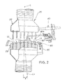
- the first quench unit 20 has a vertical axis L inclined rightward at an angle 6 to the perpendicular Lv so that the upper surface 24 of the lower quench section 22 tilts down toward the right.
- the small-thickness glass sheet 12 With this inclination of the first quench unit 20, the small-thickness glass sheet 12 while being held in a floating condition above the upper surface 24 of the floating bed 23 by the pressure of blower air is forced rightward against the edge support members 82a of the support arms 82, as indicated by the arrow a in FIG. 2.
- the right edge 13 of the small-thickness glass sheet 12 is, therefore, stably and reliably supported by the edge support members 82a of the support arms 82 during conveyance of the small-thickness glass sheet 12 through the glass quench apparatus 10.
- the pusher arm 84 and its pusher member 84a are omitted from FIG. 2.
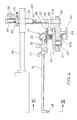
- the second quench unit 40 includes a nozzle moving device 42 for moving jet nozzles (described later) left and right and up and down, an adjusting device 60 for causing the jet nozzles to swing in both horizontal and vertical planes, and a second quench section 70 provided with the jet nozzles for jetting compressor air.
- the moving device 42 and the adjusting device 60 together form a second nozzle group moving means or unit 69.
- the moving device 42 includes a pair of parallel rodless cylinders 43, 43 cantilevered to a right side wall of the air chamber 35 of the upper quench section 32 in such a manner that the respective longitudinal axes of the rodless cylinders 43, 43 extend at an angle ⁇ to the direction of conveyance of the small-thickness glass sheet 12.
- Respective moving members 44, 44 of the rodless cylinders 43, 43 are connected together by a cross member 45.
- a nut 46 of a ball screw is mounted on a central portion of the cross member 45 so that the nut 46 is rotatable at a fixed position.
- a screw shaft 47 of the ball screw is threaded with the nut 46 and has a lower end rotatably connected to a lift plate 48.
- a driven gear 50 is attached to an upper end of the nut 46 of the ball screw and is in mesh with a drive gear 51 attached to the output shaft of a first drive motor 52.
- the drive motor 52 is vertically mounted on a bracket 53 attached to the cross member 45.
- Two upright guide rods 54, 54 fixed at lower ends thereof to the opposite ends of the lift plate 48 are slidably guided by a pair of guide sleeves (not designated) formed integrally with opposite end walls of the cross member 45.
- the adjusting device 60 includes a vertical rotary shaft 61 rotatably mounted on the lift plate 48, and a horizontal swing plate 62 attached to an upper end of the rotary shaft 61.
- the swing plate 62 comprises an elongated rectangular plate.
- a driven gear 63 is attached to a lower end of the rotary shaft 61 and is in mesh with a drive gear 63a attached to the output shaft of a second drive motor 64.
- the drive motor 64 is mounted on a bracket (not designated) attached to the underside of the lift plate 48.
- a vertical tilt plate 66 is disposed directly above the horizontal swing plate 62 and is pivotally connected at opposite ends to the opposite ends of the plate 62 by means of a pair of horizontal pins (only one being shown) 65.
- a worm gear 67 is attached to at least one of the pins 65 and is in mesh with a worm (drive gear) 67a attached to the output shaft of a third drive motor 68.
- the drive motor 68 is mounted on the horizontal swing plate 62
- the second quench section 70 includes an air-supply pipe 72 mounted on the tilt plate 66.
- the air-supply pipe 72 is closed at one end, the other end of the air-supply pipe 72 being connected by a flexible tube 73 to an air compressor 74.
- a plurality of parallel juxtaposed air-guide pipes 75 are connected at one end to a circumferential wall 72a of the air-supply pipe 72 and extend obliquely at an angle ⁇ to the axis of the air-supply pipe 72.
- the air-guide pipes 75 are spaced at uniform intervals in the longitudinal direction of the air-supply pipe 72.
- An electromagnetic valve 76 and a manual valve 77 are provided in series on a proximal end portion of each air-guide pipe 75 for controlling the flow of compressor air passing through the air-guide pipe 75.
- Respective free ends of the air-guide pipes 75 are bent downward at an angle of 90° and they are equipped with second nozzles 78.
- the second nozzles 78 form a second nozzle group 79.
- the electromagnetic valve 76 is an on-off valve operative, on the basis of a control signal supplied from a control unit (not shown), to selectively block and allow the passage of compressor air through the associated air-guide pipe 75.
- the upper and lower first nozzles 37a, 27a of the first quench unit 20 are arranged zigzag, and the air-guide pipes 75 of the second quench unit 70 extend obliquely at the angle ⁇ to the axis of the air-supply pipe 72.
- the oblique angle ⁇ of the air-guide pipes 75 is determined such that the air-guide pipes 75 extend parallel with rows of diagonally aligned ones of the first nozzles 37a, 27a (only upper first nozzles 37a being shown in FIG. 5) of the first quench unit 20.
- Each of the air-guide pipes 75 can, therefore, be located intermediately between one pair of adjacent rows of diagonally aligned first nozzles 37a (27a).
- the second nozzles 78 (forming the second nozzle group 79) at the free ends of the air-guide pipes 75 are in parallel with the direction of travel of the small-thickness glass sheet 12. In the position shown in FIG. 5, the second nozzles 78 can issue compressor air onto a central portion 15 between the right and left edges of the small-thickness glass sheet 12.
- the second quench section 70 can move the second nozzle group 79 (nozzles 78) in the direction of the arrow b shown in FIG. 5 until the second nozzle group 79 is located at a desired position relative to a glass sheet 12 to be quenched.
- the second nozzle group 79 Since the second nozzle group 79 is movable in the direction of the arrow b , it can position itself relative to the desired region of any of the small-thickness glass sheets of different sizes, so that the small-thickness glass sheets of different sizes can be quenched under optimum conditions.
- the second nozzle group 79 which is movable in the direction of the arrow b can direct blasts of compressor air onto only a desired region of the small-thickness glass sheet 12 to be quenched. Thus, wastage of the compressor air can be avoided.
- the region of the small-thickness glass sheet on which compressor air is jetted may be a central region, the right edge 13 (lower edge shown in FIG. 5), or a part of the rear edge 14 of the small-thickness glass sheet 12. This is because the central region of the small-thickness glass sheet 12 is hard to cool as compared to another region of the small-thickness glass sheet 12.
- the lower edge 13 and rear edge 14 of the small-thickness glass sheet 12 are also hard to cool because due to direct contact with the arms 82, 84, these edges 13, 14 are subjected to heat transferred from the arms 82, 84.
- the arms 82, 84 are made of metal and can retain heat received during the preceding glass bending process.
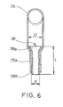
- FIG. 6 is a cross-sectional view taken along line VI-VI of FIG. 4.
- each of the second nozzles 78 is attached by clinching it to a lower end portion 75a of the downwardly bent free end of the associated air-guide pipe 75.
- the lower end portion 75a of the air-guide pipe 75 is squeezed to reduce its diameter with the second nozzle 78 held therein.
- the second nozzle 78 is a bell-mouth nozzle made, for example, of brass or copper.
- a flared upper end 78a of the bell-mouth nozzle 78 has a maximum outside diameter D greater than that d of a lower end 78b of the second nozzle 78.
- the length L and outside diameter d of the second nozzle 78 are designed to satisfy a condition expressed by the inequality L ⁇ 3x d . If L ⁇ 3x d , compressor air emitted from the second nozzle 78 tends to spread out and thus makes it difficult to achieve an accurate blasting of the compressor air onto the desired region of the small-thickness glass. In other words, by the second nozzles 78 designed to satisfy the inequality L ⁇ 3xd, blasts of compressor air issued from the nozzles 78 can be accurately directed onto the desired region of the small-thickness glass sheet.
- the outside diameter d of the second nozzle 78 as measured at the lower end 78b of the second nozzle 78 is in the range of 1.0 to 2.0 mm. This diameter is much smaller than the inside diameter D of the air-guide pipe 75.
- the air-guide pipe 75 owing to its inside diameter much larger than that of the second nozzle 78, can serve also as an air chamber, so that compressor air is issued from the second nozzles 78 at a high pressure.
- the high-pressure compressor air now possess a large cooling capacity which is sufficient to quench the desired region of the small-thickness glass sheet efficiently with minimum use of compressor air without affecting the quality of another region of the small-thickness glass sheet.
- the glass quenching apparatus 10 of the foregoing construction operates as follows.
- the drive motor 52 of the nozzle moving device 42 is driven to rotate the drive gear 51.
- Rotation of the drive gear 51 is transmitted via the driven gear 50 and the nut 46 (FIGS. 3 and 4) of the ball screw to the screw shaft 47 of the ball screw.
- the screw shaft 47 moves in an axial direction to thereby raise or lower the lift plate 48 for moving the air-guide pipes 75 in a vertical direction as indicated by the arrow 1 in a circle.
- the second nozzles 78 (FIGS. 4 and 5) can be set in a desired vertical position or level.
- the drive motor 64 (FIG. 4) of the adjusting device 60 is driven to rotate the drive gear 63a.
- Rotation of the drive gear 63a is transmitted via the driven gear 63 to the rotary shaft 61.
- the swing plate 62 turns about the axis of the rotary shaft 61 in unison with the rotary shaft 61, so that the air-guide pipes 75 cause to swing in a horizontal plane, as indicated by the arrow 2 in a circle shown in FIG. 7A.
- the air-guide pipes 75 are adjusted in position relative to the upper first nozzles 37a of the first quench unit 20 such that the air-guide pipes 75 are arranged in parallel with rows of diagonally aligned with first nozzles 37a. With this positional adjustment, the air-guide pipes 75 can be inserted into spaces between adjacent rows of diagonally aligned upper first nozzles 37a without interference with the upper first nozzles 37a, as described below.
- the rodless cylinders 43, 43 of the moving device 42 are operated to move the respective moving members 44, 44 and the cross member 45 in a direction indicated by the arrow 3 in a circle shown in FIG. 7B.
- the air-guide pipes 75 are inserted into spaces defined between the adjacent rows of diagonally aligned upper first nozzles 37a of the first quench unit 20 until the second nozzle group 79 is located in a desired position shown in FIG. 8A.
- blower air is blasted upward from the lower first nozzle group 27 of the floating bed 23 so that a small-thickness glass sheet 12 is raised in a floating condition above the floating bed 23 by the pressure of blower air.
- the floating small-thickness glass sheet 12 is urged rightward in FIG. 8A by the pressure of blower air in such a manner that the right edge 13 of the small-thickness glass sheet 12 comes into abutment with the edge support members 82a (FIGS. 2 and 5) of the support arms 82.
- the right edge 13 of the small-thickness glass sheet 12 is thus supported by the support arms 82.
- the second nozzle group 79 is disposed above a central region of the small-thickness glass sheet 12.
- the upper nozzles 37a of the upper first nozzle group 37 also jet blower air downward onto the upper surface of the small-thickness glass sheet 12.
- the drive motor 68 (FIG. 4) of the adjusting device 60 is driven to rotate the drive gear 67a.
- Rotation of the drive gear 67a is transmitted via the worm gear 67 to the pin 65.
- the tilt plate 66 turns about the axis of the pins 65 to thereby swing the air-guide pipes 75 in a vertical plane, as indicated by the arrow 4 in a circle shown in FIG. 8A.
- the distance between the second nozzle group 79 and the small-thickness glass sheet 12 i.e., nozzle distance: ND
- compressor air is blasted from the second nozzle group 78 onto the central region of the upper surface of the small-thickness glass sheet 12, as shown in FIB. 8B.
- the conveyor unit 80 shown in FIG. 9 is driven so that the drive chain 85 travels along a closed loop-like path to move the small-thickness glass sheet 12 in the direction of the profiled arrow via the movement of the support arms 82 and the pusher arm 84 of the conveyor unit 80 in the same direction.
- the central region E of the glass sheet 12 is quenched at the same degree as the other region of the glass sheet 12.
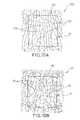
- a small-thickness glass sheet 130 quenched by a conventional quenching apparatus and a small-thickness glass sheet 12 quenched by the inventive glass quenching apparatus were tested for broken structure with the results shown in FIGS. 10A and 10B, respectively.
- a square area P bounded by phantom lines corresponds to the position P shown in FIG. 9.
- the conventional glass quenching apparatus is unable to quench the central region of the small-thickness glass sheet 130 at the same degree as the peripheral edge portion. Accordingly, the conventionally quenched glass sheet 130 when broken is likely to form elongated broken pieces (called "splines") 132, as shown in FIG. 10A, and thus fails to satisfy the standardized requirements specified for the tempered glass sheets.
- splines elongated broken pieces
- the inventive glass quenching apparatus is able to quench the central region 15 of the small-thickness glass sheet 12 at the same degree as the peripheral edge portion of the glass sheet.
- the quenched glass sheet 12 when broken forms finely broken pieces 16, as shown in FIG. 10B, and thus is able to satisfy the standardized requirement specified for the tempered glass sheets.
- the second nozzles 78 of the second quench section 70 are moved to a position located directly above a path of movement of the central region 15 of the small-thickness glass sheet 12 so that the small-thickness glass sheet 12 is quenched uniformly over the entire area thereof.
- the second nozzles 78 may be displaced to a position located above a path of movement of the right edge 13 (FIG. 5) and a portion of the rear edge 14 (FIG. 5) located close to the right edge 13.
- the edge portions 13, 14 can be quenched by compressor air in the same manner as another part of the small-thickness glass sheet 12.
- This arrangement is particularly advantageous because the right edge 13 and the rear edge portion 14, which are held in direct contact with the metal arms 82, 84 during conveyance of the glass sheet 12, are unlikely to become cool due to heat transmitted from the metal arms 82, 84.
- FIGS. 11A and 11B show a modified form of the second quench section according to the present invention.
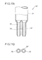
- the modified second quench section 90 includes air-guide pipes (one being shown) 91 having a larger diameter than the air-guide pipes 75 of the first embodiment shown in FIG. 6 so that two nozzles 78 can be attached by clenching to the free end of each air-guide pipe 91.
- the modified second quench section 90 (FIG. 12) is able to blast more amount of compressor air than as blasted from the second quench section 70 shown in FIGS. 1-9, so that the upper surface of the central region 15 of the small-thickness glass sheet 12 shown in FIG. 12 is quenched with improved efficiency. With this highly efficient quenching, the resulting tempered glass sheet has improved qualities.
- FIG. 13 shows in diagrammatical plan view a glass quenching apparatus 95 according to a second embodiment of the present invention.
- the glass quenching apparatus 95 differs from the apparatus 10 of the first embodiment shown in FIGS. 1-9 in that the second quench unit 40 is disposed on both left and right sides of the first quench unit 20.
- the glass quenching apparatuses of the present invention are used in the manufacture of a curved tempered glass sheet for quenching a curved small-thickness glass sheet 12 to temper the same.
- the glass quenching apparatus of the present invention can be also used for adjusting the curvature of the curved small-thickness glass sheet.
- the electromagnetic valves 76 (FIGS. 3-5) of the second quench section 70 are operated to change the cooling capacity of the quenching apparatus in such a manner that due to a difference in cooling capacity between an upper unit and a lower unit of the quenching apparatus, there arises a temperature difference between the upper and lower surfaces of the curved small-thickness glass sheet 12 being quenched.
- the widthwise curvature of the small-thickness glass sheet 12 can be adjusted.
- the glass quenching apparatus can exhibit a high operation rate and an increased rate of production of the tempered glass sheets.
- the glass quenching apparatus is used for quenching small-thickness glass sheets having a thickness in the range of 1.5 mm to 3.0 mm, the apparatus is effectively operative when used with glass sheets of a different thickness.
- the small-thickness glass sheets include float glass sheets, polished glass sheets and figured glass sheets.
- the second nozzles 78 are attached by clenching to the respective free ends of the air-guide pipes 75.
- the second nozzles 78 may be omitted in which instance the free ends of the air-guide pipes 75 are drawn or squeezed to form nozzles of a reduced diameter.
- the electromagnetic valves 76 attached to the air-guide pipes 75 of the second quench section 70 may be omitted.
- the nozzles are movable left and right and up and down by means of the nozzle moving device 42, and the nozzles are also movable to swing in both horizontal and vertical directions by means of the adjusting device 60.
- Another arrangement may be employed to achieve the foregoing movements of the nozzles.
- the glass quenching apparatus of the present invention includes a second nozzle group comprised of movable nozzles which can be positioned accurately with respect to the desired region (hard-to-cool portion) of any of the glass sheets of different sizes.
- a second nozzle group comprised of movable nozzles which can be positioned accurately with respect to the desired region (hard-to-cool portion) of any of the glass sheets of different sizes.
- the overall equipment cost of the glass quenching apparatus is relatively low and does not increase the manufacturing cost of the tempered glass sheets.
- the glass sheet while being held in a floating condition is fed along a conveyance path by means of arms of the conveyor unit. Since the second nozzle group is positioned accurately with respect to a desired region (hard-to-cool portion) of the small-thickness glass sheet, jets of compressor air issued from the second nozzle group will trace the desired region of the glass sheet as the glass sheet is conveyed by the conveyor unit. Thus the hard-to-cool portion of the glass sheet is quenched efficiently with no substantial wastage of compressor air incurred.
- the second nozzle group may be displaced to a position aligned with a path of movement of the glass sheet edge portions, so that the glass sheet edge portions are quenched by compressor air issued from the second nozzle group.
- the glass sheet is quenched uniformly over the entire area thereof and hence is able to possess improved qualities.
Landscapes
- Chemical & Material Sciences (AREA)
- Physics & Mathematics (AREA)
- Thermal Sciences (AREA)
- Engineering & Computer Science (AREA)
- Materials Engineering (AREA)
- Organic Chemistry (AREA)
- Mathematical Physics (AREA)
- Re-Forming, After-Treatment, Cutting And Transporting Of Glass Products (AREA)
- Details Or Accessories Of Spraying Plant Or Apparatus (AREA)
- Nozzles (AREA)
Applications Claiming Priority (2)
| Application Number | Priority Date | Filing Date | Title |
|---|---|---|---|
| JP11199623A JP2001026434A (ja) | 1999-07-13 | 1999-07-13 | ガラス急冷装置 |
| JP19962399 | 1999-07-13 |
Publications (2)
| Publication Number | Publication Date |
|---|---|
| EP1069085A2 true EP1069085A2 (de) | 2001-01-17 |
| EP1069085A3 EP1069085A3 (de) | 2001-09-12 |
Family
ID=16410938
Family Applications (1)
| Application Number | Title | Priority Date | Filing Date |
|---|---|---|---|
| EP00305961A Withdrawn EP1069085A3 (de) | 1999-07-13 | 2000-07-13 | Vorrichtung zum Härten von Glas |
Country Status (3)
| Country | Link |
|---|---|
| US (1) | US6412309B1 (de) |
| EP (1) | EP1069085A3 (de) |
| JP (1) | JP2001026434A (de) |
Cited By (4)
| Publication number | Priority date | Publication date | Assignee | Title |
|---|---|---|---|---|
| WO2004026777A1 (ja) * | 2002-09-04 | 2004-04-01 | Central Glass Company, Limited | 熱強化ガラス、及びその製造方法と装置 |
| RU2237621C1 (ru) * | 2003-01-27 | 2004-10-10 | Белгородская государственная технологическая академия строительных материалов | Способ закалки стекла |
| CN115745427A (zh) * | 2022-11-30 | 2023-03-07 | 东海县晶瑞达石英制品有限公司 | 一种半导体石英玻璃制品的真空脱羟炉 |
| CN116574983A (zh) * | 2023-05-18 | 2023-08-11 | 浙江缘旺门窗有限公司 | 一种铝型材的风冷淬火设备 |
Families Citing this family (29)
| Publication number | Priority date | Publication date | Assignee | Title |
|---|---|---|---|---|
| CN1212281C (zh) * | 1999-06-17 | 2005-07-27 | 旭硝子株式会社 | 玻璃板的风冷强化装置及风冷强化方法 |
| EP1380550B1 (de) | 2002-07-10 | 2011-09-21 | Asahi Glass Co., Ltd. | Vorspannende Glasscheibe mit einer zentralen Zone auf höherer Druckspannung, Verfahren und Vorrichtung seiner Herstellung |
| US20060150683A1 (en) * | 2005-01-11 | 2006-07-13 | Glasstech, Inc. | Apparatus and method for glass sheet quenching |
| US8074473B2 (en) * | 2006-12-01 | 2011-12-13 | Glasstech, Inc. | Method for quenching formed glass sheets |
| US8534096B2 (en) * | 2007-03-28 | 2013-09-17 | Glasstech, Inc. | Quench station and method for formed glass sheet quenching |
| KR100920616B1 (ko) | 2009-06-02 | 2009-10-08 | 이정호 | 곡면 강화 유리 제조를 위한 냉각 강화 장치 |
| JP5379073B2 (ja) * | 2009-06-09 | 2013-12-25 | 三星ダイヤモンド工業株式会社 | 冷却ノズル及びそれを用いた冷却方法並びに脆性材料基板の割断方法 |
| CN102459105B (zh) | 2009-06-15 | 2015-02-04 | 皮尔金顿集团有限公司 | 改进的玻璃回火方法和设备 |
| CN102471001B (zh) * | 2009-07-15 | 2015-04-22 | 东洋钢钣株式会社 | 膜漂浮搬送装置及其制造方法 |
| JP2011026169A (ja) * | 2009-07-24 | 2011-02-10 | Nippon Sheet Glass Co Ltd | 単一方向曲げガラスの製造装置、単一方向曲げガラス及び単一方向曲げガラスの製造方法 |
| FI20105257A7 (fi) * | 2010-03-15 | 2011-09-16 | Glaston Services Ltd Oy | Laite lasilevyjen lämmittämiseksi karkaisua varten |
| JP5024487B1 (ja) * | 2011-02-01 | 2012-09-12 | 旭硝子株式会社 | 磁気ディスク用ガラス基板の製造方法 |
| US11097974B2 (en) | 2014-07-31 | 2021-08-24 | Corning Incorporated | Thermally strengthened consumer electronic glass and related systems and methods |
| CA2956929A1 (en) | 2014-07-31 | 2016-02-04 | Corning Incorporated | Thermally tempered glass and methods and apparatuses for thermal tempering of glass |
| US10611664B2 (en) | 2014-07-31 | 2020-04-07 | Corning Incorporated | Thermally strengthened architectural glass and related systems and methods |
| US12338159B2 (en) | 2015-07-30 | 2025-06-24 | Corning Incorporated | Thermally strengthened consumer electronic glass and related systems and methods |
| KR102492060B1 (ko) | 2016-01-12 | 2023-01-26 | 코닝 인코포레이티드 | 얇은, 열적 및 화학적으로 강화된 유리-계 제품 |
| US11795102B2 (en) | 2016-01-26 | 2023-10-24 | Corning Incorporated | Non-contact coated glass and related coating system and method |
| WO2017173080A1 (en) | 2016-03-31 | 2017-10-05 | Dow Global Technologies Llc | Olefin polymerization catalyst systems and methods of use thereof |
| US10435779B2 (en) * | 2017-03-14 | 2019-10-08 | Ford Motor Company | Precision air flow routing devices and method for thermal spray coating applications |
| FR3068349B1 (fr) * | 2017-06-29 | 2021-10-29 | Saint Gobain | Bombage de feuilles de verre comprenant un refroidissement localise |
| WO2019040818A2 (en) | 2017-08-24 | 2019-02-28 | Corning Incorporated | GLASSES HAVING ENHANCED TEMPERATURE CAPABILITIES |
| CN107570369B (zh) * | 2017-09-08 | 2022-10-14 | 安徽省振华科技工业有限公司 | 一种达克罗涂覆的三工位加工装置 |
| TWI785156B (zh) | 2017-11-30 | 2022-12-01 | 美商康寧公司 | 具有高熱膨脹係數及對於熱回火之優先破裂行為的非離子交換玻璃 |
| CN108793702B (zh) * | 2018-07-08 | 2021-11-02 | 威海烟华安全玻璃有限公司 | 一种玻璃生产用风冷型淬火装置 |
| CN113727954A (zh) | 2019-04-23 | 2021-11-30 | 康宁股份有限公司 | 具有确定的应力分布曲线的玻璃层叠物及其制作方法 |
| US11697617B2 (en) | 2019-08-06 | 2023-07-11 | Corning Incorporated | Glass laminate with buried stress spikes to arrest cracks and methods of making the same |
| CN111499170A (zh) * | 2020-04-15 | 2020-08-07 | 福耀玻璃(苏州)有限公司 | 一种钢化bt辅助风嘴自动化机构 |
| JP7161242B1 (ja) * | 2021-04-07 | 2022-10-26 | 株式会社ヒートエナジーテック | 乾燥装置 |
Family Cites Families (13)
| Publication number | Priority date | Publication date | Assignee | Title |
|---|---|---|---|---|
| FR1205715A (fr) * | 1958-08-08 | 1960-02-04 | Saint Gobain | Procédé et dispositif pour la fabrication des feuilles de verre trempées comportant des hublots de visibilité |
| GB1212208A (en) * | 1967-07-10 | 1970-11-11 | Triplex Safety Glass Co | Method of and apparatus for differentially toughening glass sheets |
| US3665730A (en) * | 1970-06-11 | 1972-05-30 | Frederick D Linzer | Apparatus for simultaneously supporting, cooling and shaping glass sheet and the like |
| US4046543A (en) * | 1976-04-23 | 1977-09-06 | Ppg Industries, Inc. | Method and apparatus for tempering moving glass sheets |
| IE47521B1 (en) * | 1977-06-23 | 1984-04-18 | Triplex Safety Glass Co | Improvements in or relating to toughening galss sheets |
| IE47501B1 (en) * | 1977-06-23 | 1984-04-04 | Triplex Safety Glass Co | Method for thermally toughening glass sheets,in particular to be used as motor vehicle side or rear windows |
| US4402723A (en) * | 1982-01-28 | 1983-09-06 | Ppg Industries, Inc. | Nozzle arrangement for pass-through glass sheet tempering apparatus |
| US4444579A (en) * | 1982-11-10 | 1984-04-24 | Ppg Industries, Inc. | Apparatus for tempering glass sheets of different sizes and shapes |
| US4711655A (en) * | 1986-06-09 | 1987-12-08 | Ppg Industries, Inc. | Adjustable quench for tempering a glass sheet |
| JPH0624995B2 (ja) | 1990-03-19 | 1994-04-06 | セントラル硝子株式会社 | 強化ガラスの製造法 |
| FI90046C (fi) * | 1992-02-12 | 1993-12-27 | Tamglass Eng Oy | Munstycksarrangemang foer en haerdningsugn foer planglas |
| JP3271128B2 (ja) | 1993-09-20 | 2002-04-02 | ソニー株式会社 | チューナケース |
| FI945082A0 (fi) * | 1994-10-28 | 1994-10-28 | Risto Nikander | Foerfarande och anordning foer justering av glashaerdningshuvudet |
-
1999
- 1999-07-13 JP JP11199623A patent/JP2001026434A/ja active Pending
-
2000
- 2000-07-12 US US09/614,275 patent/US6412309B1/en not_active Expired - Fee Related
- 2000-07-13 EP EP00305961A patent/EP1069085A3/de not_active Withdrawn
Cited By (5)
| Publication number | Priority date | Publication date | Assignee | Title |
|---|---|---|---|---|
| WO2004026777A1 (ja) * | 2002-09-04 | 2004-04-01 | Central Glass Company, Limited | 熱強化ガラス、及びその製造方法と装置 |
| RU2237621C1 (ru) * | 2003-01-27 | 2004-10-10 | Белгородская государственная технологическая академия строительных материалов | Способ закалки стекла |
| CN115745427A (zh) * | 2022-11-30 | 2023-03-07 | 东海县晶瑞达石英制品有限公司 | 一种半导体石英玻璃制品的真空脱羟炉 |
| CN115745427B (zh) * | 2022-11-30 | 2023-10-20 | 东海县晶瑞达石英制品有限公司 | 一种半导体石英玻璃制品的真空脱羟炉 |
| CN116574983A (zh) * | 2023-05-18 | 2023-08-11 | 浙江缘旺门窗有限公司 | 一种铝型材的风冷淬火设备 |
Also Published As
| Publication number | Publication date |
|---|---|
| JP2001026434A (ja) | 2001-01-30 |
| US6412309B1 (en) | 2002-07-02 |
| EP1069085A3 (de) | 2001-09-12 |
Similar Documents
| Publication | Publication Date | Title |
|---|---|---|
| US6412309B1 (en) | Glass quenching apparatus | |
| US4204853A (en) | Glass sheet alignment means and method of using | |
| US5833729A (en) | Method and apparatus for bending glass sheets | |
| CA1112454A (en) | Method and apparatus for shaping glass sheets by roll forming | |
| EP2351713B1 (de) | Luftkühlintensivierungsvorrichtung für glasplatte und luftkühlintensivierungsverfahren | |
| KR900005385B1 (ko) | 상측 이송장치를 가진 글라스시이트 처리 시스템 (glass sheet processing system) | |
| US4300937A (en) | Quench devices, glass tempering furnaces, and methods of utilizing same | |
| US4314836A (en) | Glass sheet tempering apparatus with nozzle arrangement providing fluid escape paths and method of tempering glass sheets | |
| CN1648083B (zh) | 弯曲玻璃板的方法和设备 | |
| US5118334A (en) | Apparatus for bending glass | |
| RU2083512C1 (ru) | Устройство для формования и отпуска стеклянных листов | |
| US11852413B2 (en) | Tempering furnace for glass sheets | |
| JPS58223626A (ja) | 板ガラス支持方法及び装置 | |
| US20040244424A1 (en) | Bending system, bending method and curved roller for a glass sheet | |
| US5411128A (en) | Heated glass sheet positioning on roll conveyor | |
| US4298368A (en) | Delivering and aligning glass sheets in a bending station | |
| US4323385A (en) | Nozzle arrangement for glass sheet tempering apparatus | |
| EP1473282B1 (de) | Vorrichtung und Verfahren zum Vorspannen einer Glasscheibe | |
| CA1206336A (en) | Apparatus for tempering glass sheets of different sizes and shapes | |
| US20240239700A1 (en) | Apparatus and Method for Eliminating Stress Spots on a Surface of Glass | |
| US4830649A (en) | Method & apparatus for bending glass sheets | |
| US20060150683A1 (en) | Apparatus and method for glass sheet quenching | |
| US4402723A (en) | Nozzle arrangement for pass-through glass sheet tempering apparatus | |
| CN102007078A (zh) | 用于淬火成形的玻璃板的淬火台和方法 | |
| US4074995A (en) | Method of shaping glass sheets by the roll forming method |
Legal Events
| Date | Code | Title | Description |
|---|---|---|---|
| PUAI | Public reference made under article 153(3) epc to a published international application that has entered the european phase |
Free format text: ORIGINAL CODE: 0009012 |
|
| AK | Designated contracting states |
Kind code of ref document: A2 Designated state(s): AT BE CH CY DE DK ES FI FR GB GR IE IT LI LU MC NL PT SE Kind code of ref document: A2 Designated state(s): BE DE FR GB SE |
|
| AX | Request for extension of the european patent |
Free format text: AL;LT;LV;MK;RO;SI |
|
| PUAL | Search report despatched |
Free format text: ORIGINAL CODE: 0009013 |
|
| AK | Designated contracting states |
Kind code of ref document: A3 Designated state(s): AT BE CH CY DE DK ES FI FR GB GR IE IT LI LU MC NL PT SE |
|
| AX | Request for extension of the european patent |
Free format text: AL;LT;LV;MK;RO;SI |
|
| 17P | Request for examination filed |
Effective date: 20011116 |
|
| AKX | Designation fees paid |
Free format text: BE DE FR GB SE |
|
| 17Q | First examination report despatched |
Effective date: 20040419 |
|
| STAA | Information on the status of an ep patent application or granted ep patent |
Free format text: STATUS: THE APPLICATION IS DEEMED TO BE WITHDRAWN |
|
| 18D | Application deemed to be withdrawn |
Effective date: 20041101 |