EP1070488A1 - Verfahren zur Herstellung einer Oberflächenstruktur, insbesondere auf einem chirurgischen Implantat - Google Patents
Verfahren zur Herstellung einer Oberflächenstruktur, insbesondere auf einem chirurgischen Implantat Download PDFInfo
- Publication number
- EP1070488A1 EP1070488A1 EP00810539A EP00810539A EP1070488A1 EP 1070488 A1 EP1070488 A1 EP 1070488A1 EP 00810539 A EP00810539 A EP 00810539A EP 00810539 A EP00810539 A EP 00810539A EP 1070488 A1 EP1070488 A1 EP 1070488A1
- Authority
- EP
- European Patent Office
- Prior art keywords
- nozzle
- liquid
- bar
- jet
- high pressure
- Prior art date
- Legal status (The legal status is an assumption and is not a legal conclusion. Google has not performed a legal analysis and makes no representation as to the accuracy of the status listed.)
- Withdrawn
Links
- 239000007943 implant Substances 0.000 title claims abstract description 9
- 238000004519 manufacturing process Methods 0.000 title claims abstract description 7
- 238000000034 method Methods 0.000 title claims description 35
- 239000007788 liquid Substances 0.000 claims abstract description 31
- 239000000463 material Substances 0.000 claims abstract description 19
- 239000000758 substrate Substances 0.000 claims abstract description 18
- 239000002245 particle Substances 0.000 claims description 10
- 239000007787 solid Substances 0.000 claims description 5
- 230000008468 bone growth Effects 0.000 claims description 4
- 230000000694 effects Effects 0.000 claims description 4
- XLYOFNOQVPJJNP-UHFFFAOYSA-N water Substances O XLYOFNOQVPJJNP-UHFFFAOYSA-N 0.000 claims description 4
- 230000002328 demineralizing effect Effects 0.000 claims description 3
- 238000001914 filtration Methods 0.000 claims description 3
- 238000004381 surface treatment Methods 0.000 claims description 3
- 210000001519 tissue Anatomy 0.000 claims description 3
- -1 calcium-phosphorus compound Chemical class 0.000 claims description 2
- 238000000576 coating method Methods 0.000 claims description 2
- 239000004053 dental implant Substances 0.000 claims description 2
- 230000003628 erosive effect Effects 0.000 claims description 2
- 238000002513 implantation Methods 0.000 claims description 2
- 238000005488 sandblasting Methods 0.000 claims description 2
- 238000012546 transfer Methods 0.000 claims description 2
- 238000005299 abrasion Methods 0.000 claims 1
- 238000002679 ablation Methods 0.000 abstract description 4
- 239000010936 titanium Substances 0.000 description 4
- 210000000988 bone and bone Anatomy 0.000 description 3
- 238000010586 diagram Methods 0.000 description 3
- RTAQQCXQSZGOHL-UHFFFAOYSA-N Titanium Chemical compound [Ti] RTAQQCXQSZGOHL-UHFFFAOYSA-N 0.000 description 2
- 238000004873 anchoring Methods 0.000 description 2
- 230000000975 bioactive effect Effects 0.000 description 2
- 239000004568 cement Substances 0.000 description 2
- 238000011109 contamination Methods 0.000 description 2
- 238000003754 machining Methods 0.000 description 2
- 230000035790 physiological processes and functions Effects 0.000 description 2
- 238000012545 processing Methods 0.000 description 2
- 229910052719 titanium Inorganic materials 0.000 description 2
- 241001620634 Roger Species 0.000 description 1
- 229910001069 Ti alloy Inorganic materials 0.000 description 1
- 229910000883 Ti6Al4V Inorganic materials 0.000 description 1
- 230000001154 acute effect Effects 0.000 description 1
- 239000000654 additive Substances 0.000 description 1
- XAGFODPZIPBFFR-UHFFFAOYSA-N aluminium Chemical compound [Al] XAGFODPZIPBFFR-UHFFFAOYSA-N 0.000 description 1
- 229910052782 aluminium Inorganic materials 0.000 description 1
- 230000015572 biosynthetic process Effects 0.000 description 1
- 210000001520 comb Anatomy 0.000 description 1
- 230000003247 decreasing effect Effects 0.000 description 1
- 238000005115 demineralization Methods 0.000 description 1
- 230000001419 dependent effect Effects 0.000 description 1
- 230000012010 growth Effects 0.000 description 1
- 229910052588 hydroxylapatite Inorganic materials 0.000 description 1
- 238000007373 indentation Methods 0.000 description 1
- 238000005259 measurement Methods 0.000 description 1
- 229910001092 metal group alloy Inorganic materials 0.000 description 1
- SHTFHLQXZIRZIM-UHFFFAOYSA-K pentacalcium phosphate Chemical compound [Ca+2].[Ca+2].[Ca+2].[Ca+2].[Ca+2].[O-]P([O-])([O-])=O SHTFHLQXZIRZIM-UHFFFAOYSA-K 0.000 description 1
- XYJRXVWERLGGKC-UHFFFAOYSA-D pentacalcium;hydroxide;triphosphate Chemical compound [OH-].[Ca+2].[Ca+2].[Ca+2].[Ca+2].[Ca+2].[O-]P([O-])([O-])=O.[O-]P([O-])([O-])=O.[O-]P([O-])([O-])=O XYJRXVWERLGGKC-UHFFFAOYSA-D 0.000 description 1
- 238000002360 preparation method Methods 0.000 description 1
- 239000004576 sand Substances 0.000 description 1
- 238000001878 scanning electron micrograph Methods 0.000 description 1
- 210000002023 somite Anatomy 0.000 description 1
- 239000000126 substance Substances 0.000 description 1
- 238000012360 testing method Methods 0.000 description 1
- 238000012876 topography Methods 0.000 description 1
- GPPXJZIENCGNKB-UHFFFAOYSA-N vanadium Chemical compound [V]#[V] GPPXJZIENCGNKB-UHFFFAOYSA-N 0.000 description 1
- 229910052720 vanadium Inorganic materials 0.000 description 1
Images


Classifications
-
- B—PERFORMING OPERATIONS; TRANSPORTING
- B24—GRINDING; POLISHING
- B24C—ABRASIVE OR RELATED BLASTING WITH PARTICULATE MATERIAL
- B24C1/00—Methods for use of abrasive blasting for producing particular effects; Use of auxiliary equipment in connection with such methods
- B24C1/04—Methods for use of abrasive blasting for producing particular effects; Use of auxiliary equipment in connection with such methods for treating only selected parts of a surface, e.g. for carving stone or glass
- B24C1/045—Methods for use of abrasive blasting for producing particular effects; Use of auxiliary equipment in connection with such methods for treating only selected parts of a surface, e.g. for carving stone or glass for cutting
-
- A—HUMAN NECESSITIES
- A61—MEDICAL OR VETERINARY SCIENCE; HYGIENE
- A61F—FILTERS IMPLANTABLE INTO BLOOD VESSELS; PROSTHESES; DEVICES PROVIDING PATENCY TO, OR PREVENTING COLLAPSING OF, TUBULAR STRUCTURES OF THE BODY, e.g. STENTS; ORTHOPAEDIC, NURSING OR CONTRACEPTIVE DEVICES; FOMENTATION; TREATMENT OR PROTECTION OF EYES OR EARS; BANDAGES, DRESSINGS OR ABSORBENT PADS; FIRST-AID KITS
- A61F2/00—Filters implantable into blood vessels; Prostheses, i.e. artificial substitutes or replacements for parts of the body; Appliances for connecting them with the body; Devices providing patency to, or preventing collapsing of, tubular structures of the body, e.g. stents
- A61F2/02—Prostheses implantable into the body
- A61F2/30—Joints
- A61F2/30767—Special external or bone-contacting surface, e.g. coating for improving bone ingrowth
- A61F2/30771—Special external or bone-contacting surface, e.g. coating for improving bone ingrowth applied in original prostheses, e.g. holes or grooves
-
- B—PERFORMING OPERATIONS; TRANSPORTING
- B24—GRINDING; POLISHING
- B24C—ABRASIVE OR RELATED BLASTING WITH PARTICULATE MATERIAL
- B24C1/00—Methods for use of abrasive blasting for producing particular effects; Use of auxiliary equipment in connection with such methods
-
- B—PERFORMING OPERATIONS; TRANSPORTING
- B24—GRINDING; POLISHING
- B24C—ABRASIVE OR RELATED BLASTING WITH PARTICULATE MATERIAL
- B24C1/00—Methods for use of abrasive blasting for producing particular effects; Use of auxiliary equipment in connection with such methods
- B24C1/06—Methods for use of abrasive blasting for producing particular effects; Use of auxiliary equipment in connection with such methods for producing matt surfaces, e.g. on plastic materials, on glass
-
- B—PERFORMING OPERATIONS; TRANSPORTING
- B26—HAND CUTTING TOOLS; CUTTING; SEVERING
- B26F—PERFORATING; PUNCHING; CUTTING-OUT; STAMPING-OUT; SEVERING BY MEANS OTHER THAN CUTTING
- B26F3/00—Severing by means other than cutting; Apparatus therefor
- B26F3/004—Severing by means other than cutting; Apparatus therefor by means of a fluid jet
-
- A—HUMAN NECESSITIES
- A61—MEDICAL OR VETERINARY SCIENCE; HYGIENE
- A61C—DENTISTRY; APPARATUS OR METHODS FOR ORAL OR DENTAL HYGIENE
- A61C8/00—Means to be fixed to the jaw-bone for consolidating natural teeth or for fixing dental prostheses thereon; Dental implants; Implanting tools
- A61C8/0012—Means to be fixed to the jaw-bone for consolidating natural teeth or for fixing dental prostheses thereon; Dental implants; Implanting tools characterised by the material or composition, e.g. ceramics, surface layer, metal alloy
-
- A—HUMAN NECESSITIES
- A61—MEDICAL OR VETERINARY SCIENCE; HYGIENE
- A61F—FILTERS IMPLANTABLE INTO BLOOD VESSELS; PROSTHESES; DEVICES PROVIDING PATENCY TO, OR PREVENTING COLLAPSING OF, TUBULAR STRUCTURES OF THE BODY, e.g. STENTS; ORTHOPAEDIC, NURSING OR CONTRACEPTIVE DEVICES; FOMENTATION; TREATMENT OR PROTECTION OF EYES OR EARS; BANDAGES, DRESSINGS OR ABSORBENT PADS; FIRST-AID KITS
- A61F2/00—Filters implantable into blood vessels; Prostheses, i.e. artificial substitutes or replacements for parts of the body; Appliances for connecting them with the body; Devices providing patency to, or preventing collapsing of, tubular structures of the body, e.g. stents
- A61F2/02—Prostheses implantable into the body
- A61F2/30—Joints
- A61F2/30767—Special external or bone-contacting surface, e.g. coating for improving bone ingrowth
-
- A—HUMAN NECESSITIES
- A61—MEDICAL OR VETERINARY SCIENCE; HYGIENE
- A61F—FILTERS IMPLANTABLE INTO BLOOD VESSELS; PROSTHESES; DEVICES PROVIDING PATENCY TO, OR PREVENTING COLLAPSING OF, TUBULAR STRUCTURES OF THE BODY, e.g. STENTS; ORTHOPAEDIC, NURSING OR CONTRACEPTIVE DEVICES; FOMENTATION; TREATMENT OR PROTECTION OF EYES OR EARS; BANDAGES, DRESSINGS OR ABSORBENT PADS; FIRST-AID KITS
- A61F2/00—Filters implantable into blood vessels; Prostheses, i.e. artificial substitutes or replacements for parts of the body; Appliances for connecting them with the body; Devices providing patency to, or preventing collapsing of, tubular structures of the body, e.g. stents
- A61F2/02—Prostheses implantable into the body
- A61F2/30—Joints
- A61F2/3094—Designing or manufacturing processes
-
- A—HUMAN NECESSITIES
- A61—MEDICAL OR VETERINARY SCIENCE; HYGIENE
- A61F—FILTERS IMPLANTABLE INTO BLOOD VESSELS; PROSTHESES; DEVICES PROVIDING PATENCY TO, OR PREVENTING COLLAPSING OF, TUBULAR STRUCTURES OF THE BODY, e.g. STENTS; ORTHOPAEDIC, NURSING OR CONTRACEPTIVE DEVICES; FOMENTATION; TREATMENT OR PROTECTION OF EYES OR EARS; BANDAGES, DRESSINGS OR ABSORBENT PADS; FIRST-AID KITS
- A61F2/00—Filters implantable into blood vessels; Prostheses, i.e. artificial substitutes or replacements for parts of the body; Appliances for connecting them with the body; Devices providing patency to, or preventing collapsing of, tubular structures of the body, e.g. stents
- A61F2/02—Prostheses implantable into the body
- A61F2/30—Joints
- A61F2/32—Joints for the hip
- A61F2/36—Femoral heads ; Femoral endoprostheses
-
- A—HUMAN NECESSITIES
- A61—MEDICAL OR VETERINARY SCIENCE; HYGIENE
- A61F—FILTERS IMPLANTABLE INTO BLOOD VESSELS; PROSTHESES; DEVICES PROVIDING PATENCY TO, OR PREVENTING COLLAPSING OF, TUBULAR STRUCTURES OF THE BODY, e.g. STENTS; ORTHOPAEDIC, NURSING OR CONTRACEPTIVE DEVICES; FOMENTATION; TREATMENT OR PROTECTION OF EYES OR EARS; BANDAGES, DRESSINGS OR ABSORBENT PADS; FIRST-AID KITS
- A61F2/00—Filters implantable into blood vessels; Prostheses, i.e. artificial substitutes or replacements for parts of the body; Appliances for connecting them with the body; Devices providing patency to, or preventing collapsing of, tubular structures of the body, e.g. stents
- A61F2/02—Prostheses implantable into the body
- A61F2/30—Joints
- A61F2/32—Joints for the hip
- A61F2/36—Femoral heads ; Femoral endoprostheses
- A61F2/3662—Femoral shafts
-
- A—HUMAN NECESSITIES
- A61—MEDICAL OR VETERINARY SCIENCE; HYGIENE
- A61F—FILTERS IMPLANTABLE INTO BLOOD VESSELS; PROSTHESES; DEVICES PROVIDING PATENCY TO, OR PREVENTING COLLAPSING OF, TUBULAR STRUCTURES OF THE BODY, e.g. STENTS; ORTHOPAEDIC, NURSING OR CONTRACEPTIVE DEVICES; FOMENTATION; TREATMENT OR PROTECTION OF EYES OR EARS; BANDAGES, DRESSINGS OR ABSORBENT PADS; FIRST-AID KITS
- A61F2/00—Filters implantable into blood vessels; Prostheses, i.e. artificial substitutes or replacements for parts of the body; Appliances for connecting them with the body; Devices providing patency to, or preventing collapsing of, tubular structures of the body, e.g. stents
- A61F2/02—Prostheses implantable into the body
- A61F2/30—Joints
- A61F2/30767—Special external or bone-contacting surface, e.g. coating for improving bone ingrowth
- A61F2/30771—Special external or bone-contacting surface, e.g. coating for improving bone ingrowth applied in original prostheses, e.g. holes or grooves
- A61F2002/30795—Blind bores, e.g. of circular cross-section
- A61F2002/30807—Plurality of blind bores
- A61F2002/30808—Plurality of blind bores parallel
-
- A—HUMAN NECESSITIES
- A61—MEDICAL OR VETERINARY SCIENCE; HYGIENE
- A61F—FILTERS IMPLANTABLE INTO BLOOD VESSELS; PROSTHESES; DEVICES PROVIDING PATENCY TO, OR PREVENTING COLLAPSING OF, TUBULAR STRUCTURES OF THE BODY, e.g. STENTS; ORTHOPAEDIC, NURSING OR CONTRACEPTIVE DEVICES; FOMENTATION; TREATMENT OR PROTECTION OF EYES OR EARS; BANDAGES, DRESSINGS OR ABSORBENT PADS; FIRST-AID KITS
- A61F2/00—Filters implantable into blood vessels; Prostheses, i.e. artificial substitutes or replacements for parts of the body; Appliances for connecting them with the body; Devices providing patency to, or preventing collapsing of, tubular structures of the body, e.g. stents
- A61F2/02—Prostheses implantable into the body
- A61F2/30—Joints
- A61F2/30767—Special external or bone-contacting surface, e.g. coating for improving bone ingrowth
- A61F2/30771—Special external or bone-contacting surface, e.g. coating for improving bone ingrowth applied in original prostheses, e.g. holes or grooves
- A61F2002/3082—Grooves
- A61F2002/30827—Plurality of grooves
- A61F2002/30828—Plurality of grooves parallel
-
- A—HUMAN NECESSITIES
- A61—MEDICAL OR VETERINARY SCIENCE; HYGIENE
- A61F—FILTERS IMPLANTABLE INTO BLOOD VESSELS; PROSTHESES; DEVICES PROVIDING PATENCY TO, OR PREVENTING COLLAPSING OF, TUBULAR STRUCTURES OF THE BODY, e.g. STENTS; ORTHOPAEDIC, NURSING OR CONTRACEPTIVE DEVICES; FOMENTATION; TREATMENT OR PROTECTION OF EYES OR EARS; BANDAGES, DRESSINGS OR ABSORBENT PADS; FIRST-AID KITS
- A61F2/00—Filters implantable into blood vessels; Prostheses, i.e. artificial substitutes or replacements for parts of the body; Appliances for connecting them with the body; Devices providing patency to, or preventing collapsing of, tubular structures of the body, e.g. stents
- A61F2/02—Prostheses implantable into the body
- A61F2/30—Joints
- A61F2/30767—Special external or bone-contacting surface, e.g. coating for improving bone ingrowth
- A61F2/30771—Special external or bone-contacting surface, e.g. coating for improving bone ingrowth applied in original prostheses, e.g. holes or grooves
- A61F2002/3082—Grooves
- A61F2002/30827—Plurality of grooves
- A61F2002/30831—Plurality of grooves perpendicular with respect to each other
-
- A—HUMAN NECESSITIES
- A61—MEDICAL OR VETERINARY SCIENCE; HYGIENE
- A61F—FILTERS IMPLANTABLE INTO BLOOD VESSELS; PROSTHESES; DEVICES PROVIDING PATENCY TO, OR PREVENTING COLLAPSING OF, TUBULAR STRUCTURES OF THE BODY, e.g. STENTS; ORTHOPAEDIC, NURSING OR CONTRACEPTIVE DEVICES; FOMENTATION; TREATMENT OR PROTECTION OF EYES OR EARS; BANDAGES, DRESSINGS OR ABSORBENT PADS; FIRST-AID KITS
- A61F2/00—Filters implantable into blood vessels; Prostheses, i.e. artificial substitutes or replacements for parts of the body; Appliances for connecting them with the body; Devices providing patency to, or preventing collapsing of, tubular structures of the body, e.g. stents
- A61F2/02—Prostheses implantable into the body
- A61F2/30—Joints
- A61F2/30767—Special external or bone-contacting surface, e.g. coating for improving bone ingrowth
- A61F2002/30906—Special external or bone-contacting surface, e.g. coating for improving bone ingrowth shot- sand- or grit-blasted
-
- A—HUMAN NECESSITIES
- A61—MEDICAL OR VETERINARY SCIENCE; HYGIENE
- A61F—FILTERS IMPLANTABLE INTO BLOOD VESSELS; PROSTHESES; DEVICES PROVIDING PATENCY TO, OR PREVENTING COLLAPSING OF, TUBULAR STRUCTURES OF THE BODY, e.g. STENTS; ORTHOPAEDIC, NURSING OR CONTRACEPTIVE DEVICES; FOMENTATION; TREATMENT OR PROTECTION OF EYES OR EARS; BANDAGES, DRESSINGS OR ABSORBENT PADS; FIRST-AID KITS
- A61F2/00—Filters implantable into blood vessels; Prostheses, i.e. artificial substitutes or replacements for parts of the body; Appliances for connecting them with the body; Devices providing patency to, or preventing collapsing of, tubular structures of the body, e.g. stents
- A61F2/02—Prostheses implantable into the body
- A61F2/30—Joints
- A61F2/3094—Designing or manufacturing processes
- A61F2002/30976—Designing or manufacturing processes using hydrojet
-
- A—HUMAN NECESSITIES
- A61—MEDICAL OR VETERINARY SCIENCE; HYGIENE
- A61F—FILTERS IMPLANTABLE INTO BLOOD VESSELS; PROSTHESES; DEVICES PROVIDING PATENCY TO, OR PREVENTING COLLAPSING OF, TUBULAR STRUCTURES OF THE BODY, e.g. STENTS; ORTHOPAEDIC, NURSING OR CONTRACEPTIVE DEVICES; FOMENTATION; TREATMENT OR PROTECTION OF EYES OR EARS; BANDAGES, DRESSINGS OR ABSORBENT PADS; FIRST-AID KITS
- A61F2/00—Filters implantable into blood vessels; Prostheses, i.e. artificial substitutes or replacements for parts of the body; Appliances for connecting them with the body; Devices providing patency to, or preventing collapsing of, tubular structures of the body, e.g. stents
- A61F2/02—Prostheses implantable into the body
- A61F2/30—Joints
- A61F2/32—Joints for the hip
- A61F2/36—Femoral heads ; Femoral endoprostheses
- A61F2/3609—Femoral heads or necks; Connections of endoprosthetic heads or necks to endoprosthetic femoral shafts
- A61F2002/3625—Necks
- A61F2002/3631—Necks with an integral complete or partial peripheral collar or bearing shoulder at its base
-
- A—HUMAN NECESSITIES
- A61—MEDICAL OR VETERINARY SCIENCE; HYGIENE
- A61F—FILTERS IMPLANTABLE INTO BLOOD VESSELS; PROSTHESES; DEVICES PROVIDING PATENCY TO, OR PREVENTING COLLAPSING OF, TUBULAR STRUCTURES OF THE BODY, e.g. STENTS; ORTHOPAEDIC, NURSING OR CONTRACEPTIVE DEVICES; FOMENTATION; TREATMENT OR PROTECTION OF EYES OR EARS; BANDAGES, DRESSINGS OR ABSORBENT PADS; FIRST-AID KITS
- A61F2310/00—Prostheses classified in A61F2/28 or A61F2/30 - A61F2/44 being constructed from or coated with a particular material
- A61F2310/00005—The prosthesis being constructed from a particular material
- A61F2310/00011—Metals or alloys
- A61F2310/00023—Titanium or titanium-based alloys, e.g. Ti-Ni alloys
-
- A—HUMAN NECESSITIES
- A61—MEDICAL OR VETERINARY SCIENCE; HYGIENE
- A61F—FILTERS IMPLANTABLE INTO BLOOD VESSELS; PROSTHESES; DEVICES PROVIDING PATENCY TO, OR PREVENTING COLLAPSING OF, TUBULAR STRUCTURES OF THE BODY, e.g. STENTS; ORTHOPAEDIC, NURSING OR CONTRACEPTIVE DEVICES; FOMENTATION; TREATMENT OR PROTECTION OF EYES OR EARS; BANDAGES, DRESSINGS OR ABSORBENT PADS; FIRST-AID KITS
- A61F2310/00—Prostheses classified in A61F2/28 or A61F2/30 - A61F2/44 being constructed from or coated with a particular material
- A61F2310/00389—The prosthesis being coated or covered with a particular material
- A61F2310/00592—Coating or prosthesis-covering structure made of ceramics or of ceramic-like compounds
- A61F2310/00796—Coating or prosthesis-covering structure made of a phosphorus-containing compound, e.g. hydroxy(l)apatite
Definitions
- the invention relates to a method for producing a surface structure, in particular on a surgical implant, according to the preamble of Claim 1 and a system for performing the method and Applications of the procedure.
- the anchorage area is manufactured using a process in which geometric Space shapes created using a high pressure liquid jet become.
- Abrasive particles are added to the liquid. These particles, the traces left in the indentations created must be used for be tolerable to the human body.
- a high pressure jet that is linear over a Substrate is guided, a groove-shaped removal track is formed in the substrate, whose width is largely the same as the beam diameter or The diameter of the nozzle used is.
- the object of the invention is a method for producing a Surface structure due to material removal by means of a liquid jet create, in which a removal track arises, which is due to the generated Microstructure or microtopography particularly advantageous in terms is physiological processes. Under such physiological processes for example, the growth and ingrowth of bone tissue a hip prosthesis or an electrophysiological impact on a tissue to be stimulated, for example by means of a pacemaker electrode Roger that.
- This object is defined by what is defined in claim 1 Procedure solved.
- the dependent claims 2 to 6 relate to advantageous Embodiments of the method according to the invention.
- Subject of Claims 7 and 8 is a plant for performing the method.
- the Claims 9 to 11 relate to applications of the method.
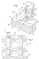
- rectilinear, groove-shaped wear marks 2 are shown a substrate 20 generated.
- the jet 1 emerges from an outlet opening 11 a nozzle 10, which at a speed v in the direction of generating track 2a is moved. It hits in an impact zone 3 (Removal site) on the surface 20a of the substrate 20.
- dash-dotted lines 2b are outlines of wear marks given subsequently arise when the removal process is continued.
- the angle ⁇ is different when machining metallic alloys with advantage around 30 °; the material removal is for this angle particularly effective.
- the outlet opening 11 of the nozzle 10 has a diameter d; it is at a distance a from the Action zone 3.
- the diameter d namely the nozzle diameter, is in essentially also the diameter of the emerging jet 1.
- Water is advantageously used as the liquid for the high-pressure jet, this is particularly true in the manufacture of surface structures surgical implants should be prepared, one preparation Filtering, demineralizing and adding additives can include. But it is also possible to use a liquid that is corrosive to the Acts on substrate. One can also find solid particles in the liquid suspend the abrasive effect when it hits impact zone 3 unfold. In the case of surgical implants, it can be advantageous without them Solid particles work so that there is no contamination of the machining surface arises from residues of the solid particles. However, biocompatible solid particles can be used that are inert, are bioactive or degradable. One example is a bioactive substance Pentacalcium phosphate (hydroxyapatite) or another calcium phosphorus compound, which promotes bone growth.
- Pentacalcium phosphate hydroxyapatite
- another calcium phosphorus compound which promotes bone growth.
- the jet 1 strikes particles from the surface 20a in the action zone 3 washed away to the side.
- the laterally flowing liquid 12 is removed with the participation of the released particles further material from the Substrate 20.
- the surface 21 thus exposed the groove 2 has a jagged microtopography, which is called "quasi-fractal” can be referred to (see the following explanations on fractal analyzes in connection with Figures 3 to 5).
- Are the straight lines 30 and 31 with the vector of the velocity v in a common plane a shape of the groove 2, the cross section of which is symmetrical.
- the high-pressure jet 1 is generally continuously applied to the substrate 20 sprayed on. However, it is also possible to use a pulsed beam 1 use.
- a macrotopography is created that is formed by parallel, rectilinear wear marks 2. Between A neighboring ridge 22 is left standing.
- the single ones Tracks 2 can also be arranged very close to each other, see above that practically no burrs 22 can be seen anymore: one is created Largely flat surface with quasi-fractal microtopography.
- the result 2 'of a macrotopography generated in this way is shown in FIG. 2 shown (drawn from a SEM image).
- the created relief structure 2 ' is checkered.
- the individual fields are troughs 23, which are formed by combs 22 'are delimited from each other.
- In the corner points of these fields are Islands 24 with remnants of the original surface 20a of the substrate 20 visible.
- the processed material is a titanium alloy (Ti-6Al-4V: titanium with 6% by weight aluminum and 4% by weight vanadium).
- the distance between the Corner points is 1 mm.
- a raster structure as shown in Fig. 2, can also be more rational with a multiple nozzle, with a number of Nozzle openings arranged on a series of equidistant points are, a family of parallel tracks 2 can be generated simultaneously.
- FIG. 3 shows the profile of a cross section through the relief structure 2 ′ shown in FIG. 2.
- the profile is shown as curve 4 over an x-axis.
- the lengths of the lines A 0 , A 1 , ... or A 0 ', A 1 ' , ... determined and compared.
- a graphic comparison is given in FIG. 4.
- the total distance 5 represents the length on the x-axis; the total distances 6 and 6 'the lengths of the lines A 0 , A 1 , ... and A 0 ', A 1 ', ... Obviously, these lengths are greater, the finer the division ⁇ x of the x-axis is.
- this length gives a measure of the fractality of the profile 4. If this function increases continuously with decreasing ⁇ x, and to a minimum ⁇ x, which cannot be undercut due to metrological reasons, the measured value is used here for the microtopography Profiles the term "quasi-fractal" used. In a common fractal analysis, the procedure is somewhat different: the route sections between adjacent points A i are specified as constant variables (so that the intervals ⁇ x are variable).
- FIG. 5 shows results of a corresponding fractal analysis for three samples made of pure titanium cpTi (commercial pure Ti). In this analysis, instead of increasing lengths, the enlargement of a surface F whose surface elements are triangles was determined. The results for F - based on the base area F 0 - are entered in the diagram.
- the distance a between the outlet opening 11 of the nozzle 10 and the Action zone 3 can be between about 0.1 - 20 mm.
- the collimator tube 13 shields the beam 1 from the surroundings, so that the distance a between outlet opening 11 and exposure zone 3 can be greater than the stated distance of 20 mm, without significantly affecting the quality of the beam 1 is coming.
- a connecting pipe 14 is additionally shown through which High pressure liquid is fed into the nozzle 10.
- the removal track 2 does not have to be as in the examples in FIGS. 1 and 2 be straightforward.
- - as shown in FIG. 8 - are guided along a meandering curve 8.
- Is curve 8 the Center line of a sufficiently wide removal track 2 so that there are no burrs form between adjacent curve sections, it results from the Meander a relatively wide streak with a single pass.
- each ablation track can be done by a single or multiple Repeat the ablation process to be deepened. If, however, at in a first pass, the surface to be machined is largely intact remains, further runs usually do not lead to the formation of one usable removal track. However, at a first Passage along the removal curve of individual crater-like depressions arise. These recesses can then be seen in further runs enlarge and finally lead to a fully excavated groove.
- Fig. 2 While a macrotopography is shown in Fig. 2, that with two shares 9 is made of intersecting, straight-line tracks corresponding pattern of wear marks, in which the Surface structuring with three panels 9, 9 'and 9 "is formed. There are only the center lines to the wear marks are shown. With small circles 25 the places are marked where island-like surveys - corresponding to the islands 24 in Fig. 2- can remain.
- the method according to the invention can also be used with other methods can be combined: in a first or second step, another Process for a surface treatment, for example a sandblast or a coating process.
- another Process for a surface treatment for example a sandblast or a coating process.
- Sandblasting is preferably done in the first step applied to the second step using a particle-free liquid any contamination caused by sand particles to be able to eliminate.
- a particularly advantageous application of the method according to the invention is the surface structuring of a joint prosthesis that is suitable for a cementless implantation is provided.
- the Shaft surface can be structured in a suitable way so that bone growth is promoted.
- the described quasi-fractal microtopography is included particularly suitable.
- a macro topography as shown in FIG. 2 additionally enables good anchoring during the initial phase, during the connection between the bone and prosthesis still very much is weakly trained.
- a corresponding application is also at Dental implants are advantageous where the implant is in a jaw a bone growth must gain a stable hold.
- the method according to the invention can be applied to zones of the Roughen the surface on which the cement must adhere.
- Electrophysiological electrodes for example in Pacemakers or defibrillators.
- poles are structured on their surfaces in order to - thanks to a large specific surface - an effective energy transfer from the To get pole on a tissue to be influenced physiologically.
- Tension measurements are quasi-fractal microtopography also particularly suitable here.
- Fig. 10 is a system for performing the represented method according to the invention. It includes the following: Means for generating a relative speed between the processing body 200 (here a hip prosthesis) and the Abtragstelle 3 on the body, namely a device 100 for controlled movement of the nozzle 10 and a device 102 with a controlled movable bracket 201 for the body 200; furthermore a electronic programmable controller 102 for the devices 100 and 202.
- the nozzle 10 or the body 200 can also each in one be held in a fixed position.
- the nozzle 10 (with the collimator tube 13) is connected to a subsystem via a flexible pressure line 14 includes or may include: a high pressure pump 101 for the Generation of the liquid jet, not shown, and a device 103 for processing the liquid, in particular for filtration and / or demineralization of the liquid. It can also be a reservoir for the liquid should be provided in a suitably prepared form (not shown).
Landscapes
- Engineering & Computer Science (AREA)
- Mechanical Engineering (AREA)
- Health & Medical Sciences (AREA)
- Life Sciences & Earth Sciences (AREA)
- Heart & Thoracic Surgery (AREA)
- Oral & Maxillofacial Surgery (AREA)
- Transplantation (AREA)
- Biomedical Technology (AREA)
- Cardiology (AREA)
- Vascular Medicine (AREA)
- Orthopedic Medicine & Surgery (AREA)
- Animal Behavior & Ethology (AREA)
- General Health & Medical Sciences (AREA)
- Public Health (AREA)
- Veterinary Medicine (AREA)
- Forests & Forestry (AREA)
- Prostheses (AREA)
Abstract
Description
- Fig. 1
- einen Materialabtrag in Form von geradlinigen Abtragsspuren, welcher mit dem erfindungsgemässen Verfahren mittels eines Hochdruck-Flüssigkeitsstrahls durchgeführt wird,
- Fig. 2
- ein Ergebnis des erfindungsgemässen Verfahrens,
- Fig. 3
- ein Profil einer erfindungsgemäss bearbeiteten Oberfläche,
- Fig. 4
- Teilergebnisse einer Fraktalanalyse zum Profil der Fig. 3,
- Fig. 5
- Diagramme zu Fraktalanalysen,
- Fig. 6
- einen Düsenkopf mit Kollimatorrohr,
- Fig. 7
- ein Profil einer asymmetrischen Abtragsspur,
- Fig. 8
- eine Mittellinie zu einer mäandrischen Abtragsspur,
- Fig. 9
- Mittellinien zu Abtragsspuren, die mit drei Scharen von sich kreuzenden, geradlinigen Spuren hergestellt sind, und
- Fig. 10
- eine Anlage zum Durchführen des erfindungsgemässen Verfahrens.
Claims (11)
- Verfahren zur Herstellung einer Oberflächenstruktur, insbesondere auf einem chirurgischen Implantat, durch Materialabtrag mittels eines Flüssigkeitsstrahls (1), der aus einer Düse (10) unter hohem Druck (p) abgegeben wird, wobei eine Abtragsstelle (3) auf einer zu strukturierenden Oberfläche (20a) eines Substrats (20) unter Erzeugung einer vorgegebenen Makrotopographie (2') oder einer weitgehend planen Oberfläche gesteuert bewegt wird, nämlich durch Bewegen der Düse und/oder des Substrats,
dadurch gekennzeichnet, dass die Flüssigkeit des Hochdruckstrahls (1) bei einem vorgegebenen Durchmesser d der Düse mit einem genügend hohen Druck p abgegeben wird, so dass durch den Materialabtrag eine lineare Spur (2) mit quasi-fraktaler Mikrotopographie (4) erzeugt wird, wobei die Spurbreite D mindestens doppelt so gross ist wie d und wobei für p und d Werte in folgenden Bereichen vorgesehen sind:100 bar < p < 3000 bar und 0.1 mm < d < 10 mm;oder p > 3000 bar und d > 0.03 mm. - Verfahren nach Anspruch 1, dadurch gekennzeichnet, dass als Flüssigkeit (1) ein Medium verwendet wird, das weitgehend frei von Feststoffpartikeln ist, und dass diese Flüssigkeit insbesondere Wasser ist, vorzugsweise geeignet aufbereitetes Wasser.
- Verfahren nach Anspruch 1 oder 2, dadurch gekennzeichnet, dass eine Schar von Abtragsspuren (2) erzeugt wird, die lokal weitgehend parallel sind, wobei zwischen benachbarten Spuren jeweils ein gut erkennbarer Grat (22) oder ein praktisch nicht erkennbarer Grat sichtbar ist, oder dass eine nichtlineare Abtragsspur (8) erzeugt wird, deren Verlauf insbesondere mäanderförmig ist.
- Verfahren nach Anspruch 3, dadurch gekennzeichnet, dass zwei oder mehr Scharen (29, 29', 29") von Spuren (2) in einer kreuzweisen Anordnung übereinander aufgebracht werden.
- Verfahren nach einem der Ansprüche 1 bis 4, dadurch gekennzeichnet, dass der Abstand (a) zwischen einer Austrittsöffnung (11) der Düse (10) und der zu bearbeitenden Oberfläche (20a) rund 0.1 - 20 mm beträgt und dass der Winkel (β = 90° - α) zwischen dem Flüssigkeitsstrahl (1) und der erzeugten Abtragsspur (2) 90° oder vorzugsweise kleiner als 90° ist.
- Verfahren nach einem der Ansprüche 1 bis 5, dadurch gekennzeichnet, dass in einem ersten oder zweiten Schritt ein weiteres Verfahren zu einer Oberflächenbehandlung, beispielsweise ein Sandstrahl- oder ein Beschichtungsverfahren, angewendet wird, wobei das Sandstrahlverfahren vorzugsweise in dem ersten Schritt angewendet wird.
- Anlage zum Durchführen des Verfahrens gemäss einem der Ansprüche 1 bis 6, folgende Komponenten umfassend: Mittel (100, 202) zum Erzeugen einer Relativgeschwindigkeit (v) zwischen dem zu bearbeitenden Körper (200) und der Abtragsstelle, nämlich eine gesteuert bewegbare Halterung (100) für die Düse (10) und/oder eine gesteuert bewegbare Halterung (201) für den Körper, wobei entweder die Düse oder der Körper in einer raumfesten Position gehalten werden kann,
ferner eine elektronische, programmierbare Steuereinrichtung (102) für die Mittel (100, 202) zum Erzeugen der Relativgeschwindigkeit und eine Hochdruckpumpe (101) für eine Erzeugung des Flüssigkeitsstrahls (1). - Anlage nach Anspruch 7, dadurch gekennzeichnet, dass eine Einrichtung (103) zum Aufbereiten der Flüssigkeit, insbesondere zu einer Filtrierung und/oder Entmineralisierung der Flüssigkeit, vorgesehen ist oder dass ein Reservoir für die Flüssigkeit in geeignet aufbereiteter Form vorgesehen ist.
- Anwendung des Verfahrens gemäss einem der Ansprüche 1 bis 5, dadurch gekennzeichnet, dass Schaftoberflächen von Gelenkprothesen, die vorzugsweise für eine zementlose Implantation vorgesehen sind, oder Oberflächen von Dentalimplantaten strukturiert werden, wobei die zu strukturierenden Oberflächen in einer Vor- oder Nachbehandlung mit einem das Knochenwachstum fördernden Material, insbesondere einer Calcium-Phosphor-Verbindung, beschichtet werden.
- Anwendung des Verfahrens gemäss einem der Ansprüche 1 bis 5, dadurch gekennzeichnet, dass bei einer elektrophysiologischen Elektrode ein Pol an dessen Oberfläche strukturiert wird, um - dank einer grossen spezifischen Oberfläche - eine wirkungsvolle Energieübertragung von dem Pol auf ein physiologisch zu beeinflussendes Gewebe zu erhalten, wobei die Elektrode insbesondere Teil eines Herzschrittmachers oder eines Defibrillators ist.
- Anwendung des Verfahrens gemäss einem der Ansprüche 1 bis 5, dadurch gekennzeichnet, dass Werkstoffe bearbeitet werden, nämlich zurErzeugung von Strukturen an homogenen, quasiisotropen Werkstoffen, um beispielsweise eine Welligkeit oder einen Orangenhauteffekt zu erzielen, oderStrukturierung von inhomogenen Werkstoffen, wobei unterschiedliches Verhalten bezüglich Löslichkeit oder Erosion genutzt werden.
Priority Applications (1)
| Application Number | Priority Date | Filing Date | Title |
|---|---|---|---|
| EP00810539A EP1070488A1 (de) | 1999-07-19 | 2000-06-20 | Verfahren zur Herstellung einer Oberflächenstruktur, insbesondere auf einem chirurgischen Implantat |
Applications Claiming Priority (3)
| Application Number | Priority Date | Filing Date | Title |
|---|---|---|---|
| EP99810651 | 1999-07-19 | ||
| EP99810651 | 1999-07-19 | ||
| EP00810539A EP1070488A1 (de) | 1999-07-19 | 2000-06-20 | Verfahren zur Herstellung einer Oberflächenstruktur, insbesondere auf einem chirurgischen Implantat |
Publications (1)
| Publication Number | Publication Date |
|---|---|
| EP1070488A1 true EP1070488A1 (de) | 2001-01-24 |
Family
ID=26073922
Family Applications (1)
| Application Number | Title | Priority Date | Filing Date |
|---|---|---|---|
| EP00810539A Withdrawn EP1070488A1 (de) | 1999-07-19 | 2000-06-20 | Verfahren zur Herstellung einer Oberflächenstruktur, insbesondere auf einem chirurgischen Implantat |
Country Status (1)
| Country | Link |
|---|---|
| EP (1) | EP1070488A1 (de) |
Cited By (4)
| Publication number | Priority date | Publication date | Assignee | Title |
|---|---|---|---|---|
| EP1304395A1 (de) * | 2001-10-19 | 2003-04-23 | Sulzer Markets and Technology AG | Verfahren zum Herstellen einer thermischen Spritzschicht |
| DE102005061401A1 (de) * | 2005-12-22 | 2007-06-28 | Robert Bosch Gmbh | Verfahren zur Mikrostrukturierung einer Oberfläche eines Werkstücks |
| DE102013211324A1 (de) * | 2013-06-17 | 2014-12-18 | Dürr Ecoclean GmbH | Verfahren und Anlage zum Vorbereiten und Beschichten einer Werkstückoberfläche |
| WO2021115704A1 (de) * | 2019-12-10 | 2021-06-17 | Robert Bosch Gmbh | Verfahren zur oberflächenbehandlung eines implantats |
Citations (2)
| Publication number | Priority date | Publication date | Assignee | Title |
|---|---|---|---|---|
| EP0417034A1 (de) * | 1989-09-06 | 1991-03-13 | SULZER Medizinaltechnik AG | Implantat mit Verankerungsflächen für Knochengewebe |
| US5681616A (en) * | 1994-12-28 | 1997-10-28 | General Electric Company | Thick thermal barrier coating having grooves for enhanced strain tolerance |
-
2000
- 2000-06-20 EP EP00810539A patent/EP1070488A1/de not_active Withdrawn
Patent Citations (2)
| Publication number | Priority date | Publication date | Assignee | Title |
|---|---|---|---|---|
| EP0417034A1 (de) * | 1989-09-06 | 1991-03-13 | SULZER Medizinaltechnik AG | Implantat mit Verankerungsflächen für Knochengewebe |
| US5681616A (en) * | 1994-12-28 | 1997-10-28 | General Electric Company | Thick thermal barrier coating having grooves for enhanced strain tolerance |
Non-Patent Citations (4)
| Title |
|---|
| HOCHENG H ET AL: "FEASIBILITY STUDY OF ABRASIVE-WATERJET MILLING OF FIBER-REINFORCED PLASTICS", TRANSACTIONS OF THE AMERICAN SOCIETY OF MECHANICAL ENGINEERS, SERIES B: JOURNAL OF ENGINEERING FOR INDUSTRY,US,ASME. NEW YORK, vol. 119, no. 2, pages 133-142, XP000696386, ISSN: 0022-0817 * |
| KNAUPP M: "PROZESSKONTROLLE BEIM HOCHDRUCKWASSER- UND WASSERABRASIVSTRAHLSCHNEIDEN", VDI Z,DE,VDI VERLAG GMBH. DUSSELDORF, vol. 135, pages 6-11, XP000402850, ISSN: 0042-1766 * |
| MOMBER A: "AKTUELLE PROBLEME DER ABRASIV-WASSERSTRAHL-BEARBEITUNG", WERKSTATTSTECHNIK,DE,SPRINGER VERLAG. BERLIN, vol. 81, no. 7, pages 437-441, XP000287302, ISSN: 0340-4544 * |
| WULF, CH.: "Qualitätsbestimmende Einflussgrössen beim Wasserstrahlschneiden", INDUSTRIE ANZEIGER,DE,KONRADIN VERLAG, LEINFELDEN, vol. 105, no. 70, 2 September 1983 (1983-09-02), pages 101 - 102, XP002128571 * |
Cited By (4)
| Publication number | Priority date | Publication date | Assignee | Title |
|---|---|---|---|---|
| EP1304395A1 (de) * | 2001-10-19 | 2003-04-23 | Sulzer Markets and Technology AG | Verfahren zum Herstellen einer thermischen Spritzschicht |
| DE102005061401A1 (de) * | 2005-12-22 | 2007-06-28 | Robert Bosch Gmbh | Verfahren zur Mikrostrukturierung einer Oberfläche eines Werkstücks |
| DE102013211324A1 (de) * | 2013-06-17 | 2014-12-18 | Dürr Ecoclean GmbH | Verfahren und Anlage zum Vorbereiten und Beschichten einer Werkstückoberfläche |
| WO2021115704A1 (de) * | 2019-12-10 | 2021-06-17 | Robert Bosch Gmbh | Verfahren zur oberflächenbehandlung eines implantats |
Similar Documents
| Publication | Publication Date | Title |
|---|---|---|
| DE69421821T2 (de) | Implantat | |
| DE69432184T2 (de) | Chirurgisch implantierbare prothesenteile | |
| EP1982007B1 (de) | Verfahren zur herstellung eines metallkörpers sowie metallkörper | |
| DE69012832T2 (de) | Herstellung von prothesen. | |
| DE69533448T2 (de) | Preparierung einer implantatoberfläche | |
| EP1440669B1 (de) | Knochenimplantat und Verfahren zu seiner Herstellung | |
| DE102004044738A1 (de) | Verfahren zur Erzeugung einer Strukturierung von Metalloberflächen sowie nach diesem Verfahren hergestellte Bauteile | |
| WO2001012259A1 (de) | Elektrodenkatheter mit reduzierter störaktivität sowie diesbezügliches behandlungsverfahren der elektrodenoberfläche | |
| DE69201850T2 (de) | Vorrichtung zur durchführung einer iontophoretischen behandlung bei einem patienten. | |
| DE19537872C2 (de) | Aufweitbare Gefäßstütze und Verfahren zu ihrer Herstellung | |
| DE60224278T2 (de) | Implantat, beispielsweise zahnimplantat | |
| EP1039991A2 (de) | Verfahren zur trennenden und/oder abtragenden bearbeitung von vorgefertigten kunststoff-folien | |
| EP1978887A1 (de) | Implantat und verfahren zur herstellung eines implantats | |
| EP0417034A1 (de) | Implantat mit Verankerungsflächen für Knochengewebe | |
| US6482076B1 (en) | Method for producing a surface structure, in particular on a surgical implant | |
| EP1070488A1 (de) | Verfahren zur Herstellung einer Oberflächenstruktur, insbesondere auf einem chirurgischen Implantat | |
| EP0841877B1 (de) | Im mund zu tragende zahntechnische vorrichtung, insbesondere in form eines brackets | |
| EP0951260A1 (de) | Vorrichtung und verfahren zur formgebung von oberflächen | |
| EP1475053B1 (de) | Verfahren zur Herstellung eines medizinischen Implantates | |
| DE4102258A1 (de) | Verfahren zur herstellung einer negativform | |
| DE29810818U1 (de) | Zementfrei implantierbare Endoprothese aus Metall | |
| EP4267212B1 (de) | Verfahren zur herstellung eines oberflächenmodifizierten metallimplantats | |
| DE19518994C1 (de) | Formkörper aus Verbundwerkstoff, insbesondere Implantat und Verfahren zu dessen Herstellung | |
| DE4417643A1 (de) | Im Mund zu tragende zahntechnische Vorrichtung, insbesondere in Form eines Brackets | |
| WO2021115704A1 (de) | Verfahren zur oberflächenbehandlung eines implantats |
Legal Events
| Date | Code | Title | Description |
|---|---|---|---|
| PUAI | Public reference made under article 153(3) epc to a published international application that has entered the european phase |
Free format text: ORIGINAL CODE: 0009012 |
|
| AK | Designated contracting states |
Kind code of ref document: A1 Designated state(s): AT BE CH CY DE DK ES FI FR GB GR IE IT LI LU MC NL PT SE |
|
| AX | Request for extension of the european patent |
Free format text: AL;LT;LV;MK;RO;SI |
|
| RAP1 | Party data changed (applicant data changed or rights of an application transferred) |
Owner name: SULZER MARKETS AND TECHNOLOGY AG |
|
| 17P | Request for examination filed |
Effective date: 20010626 |
|
| AKX | Designation fees paid |
Free format text: AT BE CH CY DE DK ES FI FR GB GR IE IT LI LU MC NL PT SE |
|
| RAP1 | Party data changed (applicant data changed or rights of an application transferred) |
Owner name: ZIMMER GMBH |
|
| 17Q | First examination report despatched |
Effective date: 20071108 |
|
| STAA | Information on the status of an ep patent application or granted ep patent |
Free format text: STATUS: THE APPLICATION IS DEEMED TO BE WITHDRAWN |
|
| 18D | Application deemed to be withdrawn |
Effective date: 20080520 |