EP1070545A2 - Procédé et appareil de fabrication d'éléments bicolores - Google Patents
Procédé et appareil de fabrication d'éléments bicolores Download PDFInfo
- Publication number
- EP1070545A2 EP1070545A2 EP00115328A EP00115328A EP1070545A2 EP 1070545 A2 EP1070545 A2 EP 1070545A2 EP 00115328 A EP00115328 A EP 00115328A EP 00115328 A EP00115328 A EP 00115328A EP 1070545 A2 EP1070545 A2 EP 1070545A2
- Authority
- EP
- European Patent Office
- Prior art keywords
- separator member
- edge region
- reservoir
- liquids
- liquid
- Prior art date
- Legal status (The legal status is an assumption and is not a legal conclusion. Google has not performed a legal analysis and makes no representation as to the accuracy of the status listed.)
- Withdrawn
Links
Images


Classifications
-
- B—PERFORMING OPERATIONS; TRANSPORTING
- B05—SPRAYING OR ATOMISING IN GENERAL; APPLYING FLUENT MATERIALS TO SURFACES, IN GENERAL
- B05B—SPRAYING APPARATUS; ATOMISING APPARATUS; NOZZLES
- B05B3/00—Spraying or sprinkling apparatus with moving outlet elements or moving deflecting elements
- B05B3/001—Spraying or sprinkling apparatus with moving outlet elements or moving deflecting elements incorporating means for heating or cooling, e.g. the material to be sprayed
-
- B—PERFORMING OPERATIONS; TRANSPORTING
- B01—PHYSICAL OR CHEMICAL PROCESSES OR APPARATUS IN GENERAL
- B01J—CHEMICAL OR PHYSICAL PROCESSES, e.g. CATALYSIS OR COLLOID CHEMISTRY; THEIR RELEVANT APPARATUS
- B01J2/00—Processes or devices for granulating materials, e.g. fertilisers in general; Rendering particulate materials free flowing in general, e.g. making them hydrophobic
- B01J2/02—Processes or devices for granulating materials, e.g. fertilisers in general; Rendering particulate materials free flowing in general, e.g. making them hydrophobic by dividing the liquid material into drops, e.g. by spraying, and solidifying the drops
-
- B—PERFORMING OPERATIONS; TRANSPORTING
- B05—SPRAYING OR ATOMISING IN GENERAL; APPLYING FLUENT MATERIALS TO SURFACES, IN GENERAL
- B05B—SPRAYING APPARATUS; ATOMISING APPARATUS; NOZZLES
- B05B3/00—Spraying or sprinkling apparatus with moving outlet elements or moving deflecting elements
- B05B3/02—Spraying or sprinkling apparatus with moving outlet elements or moving deflecting elements with rotating elements
- B05B3/10—Spraying or sprinkling apparatus with moving outlet elements or moving deflecting elements with rotating elements discharging over substantially the whole periphery of the rotating member
-
- B—PERFORMING OPERATIONS; TRANSPORTING
- B05—SPRAYING OR ATOMISING IN GENERAL; APPLYING FLUENT MATERIALS TO SURFACES, IN GENERAL
- B05B—SPRAYING APPARATUS; ATOMISING APPARATUS; NOZZLES
- B05B3/00—Spraying or sprinkling apparatus with moving outlet elements or moving deflecting elements
- B05B3/02—Spraying or sprinkling apparatus with moving outlet elements or moving deflecting elements with rotating elements
- B05B3/10—Spraying or sprinkling apparatus with moving outlet elements or moving deflecting elements with rotating elements discharging over substantially the whole periphery of the rotating member
- B05B3/1057—Spraying or sprinkling apparatus with moving outlet elements or moving deflecting elements with rotating elements discharging over substantially the whole periphery of the rotating member with at least two outlets, other than gas and cleaning fluid outlets, for discharging, selectively or not, different or identical liquids or other fluent materials on the rotating element
-
- G—PHYSICS
- G02—OPTICS
- G02B—OPTICAL ELEMENTS, SYSTEMS OR APPARATUS
- G02B26/00—Optical devices or arrangements for the control of light using movable or deformable optical elements
- G02B26/02—Optical devices or arrangements for the control of light using movable or deformable optical elements for controlling the intensity of light
- G02B26/026—Optical devices or arrangements for the control of light using movable or deformable optical elements for controlling the intensity of light based on the rotation of particles under the influence of an external field, e.g. gyricons, twisting ball displays
Definitions
- This invention relates generally to forming bichromal elements to be used in a gyricon display, and more specifically provides a new method and apparatus for supplying hardenable liquid to the surfaces of a spinning disk configuration used to fabricate the bichromal elements.
- Gyricon sheet material also known as electric paper
- U.S. Patent No. 4,126,854 describes how to make and use gyricon sheet material containing bichromal spherical elements.
- U.S. Patent No. 4,126,854 describes a thin transparent sheet having many of the attributes of paper. That is, the sheet is lightweight, flexible, can be easily read in ambient light, and retains displayed information for long periods of time with needing to refresh the displayed information.
- the sheet comprises an elastomeric host material which is heavily loaded with substantially hemispherically colored bichromal spherical elements.
- Each hemisphere is differently colored, such as black and white, red and white or any other combination of colors desired.
- Each element is further contained within its own substantially spherical cavity in a dielectric liquid. When an electric field is placed across the sheet material the elements rotate such that they line up with the electric field. The elements can therefore be rotated to display either colored hemisphere or even to display a portion of both hemispheres.
- U.S. Patent No. 5,825,529 describes another embodiment of gyricon material. As described in U.S. Patent No. 5,825,529, the spherical elements are closely packed in a stable arrangement, such as a hexagonally packed monolayer directly in the dielectric liquid. The elements in the dielectric fluid are then sandwiched between two retaining members and sealed in. In operation, this embodiment works as described above.
- EP 0942405 describes yet another embodiment of gyricon sheet material.
- a sheet material is described similar in nature to the sheet material described in U.S. Patent No. 4,126,854.
- EP 0942405 several different populations of bichromal elements are used to implement grey scale, highlight color and additive full color. The different populations of the bichromal elements are disposed in addressable subpixel areas.
- U.S. Patent No. 6055091 describes yet another embodiment of a display utilizing rotating bichromal elements.
- a display is described which uses substantially cylindrical elements.
- the cylinders reside in a dielectric liquid and their orientation can be changed by applying an electric field.
- U.S. Patent No. 5,262,098 describes a feed mechanism which uses a rotatable dispensing assembly with two liquid metering members with the rotatable disk supported therebetween.
- the lower metering member includes a spindle portion, mountable upon and rotatable by a motor, a coupling extension having a central bore for receiving liquid, a number of radially extending, upwardly angled liquid supply ports, a circular reservoir, and a circular metering lip for delivering a thin layer of liquid to the lower surface of the spinning disk.
- the upper metering member encircles the coupling extension and is secured in place by a locking nut.
- the upper metering member contains an inner groove communicating with a number of radially extending, downwardly angled liquid supply ports which in turn, communicate with a circular reservoir and a circular metering lip for delivering a thin layer of liquid to the upper surface of the disk.
- a stationary liquid delivery assembly is seated upon the rotatable dispensing assembly for delivering the two liquids to their respective surfaces of the disk.
- the present invention provides an improved apparatus and method of use which exhibits reduced clogging when used for extended periods of time.
- an apparatus for fabricating bichromal elements which has a separator member having a central rotating point comprising first and second spaced apart, opposed surfaces with an edge region in contact with both of the opposed surfaces.
- the apparatus further includes an apparatus for dispensing first and second differently colored hardenable liquids substantially at the central rotating point of the first and second surfaces, respectively, and an apparatus for substantially uniformly spreading the liquid material over the first and second surfaces toward said edge region to form a reservoir of liquid material outboard of said edge region which is comprised of side-by-side regions of the first and second differently colored hardenable liquids, and for forming ligaments from the reservoir.
- the heat source comprises a radiant shroud heater.
- the heat source comprises a clam-shell heater.
- the apparatus for dispensing first and second differently colored hardenable liquids substantially at the central rotating point of the first and second surfaces respectively includes controlling the dispensing rate of each stream.
- the apparatus for substantially uniformly spreading the liquid material over the first and second surfaces toward said edge region to form a reservoir of liquid material outboard of said edge region, and for forming ligaments from said reservoir includes forming a reservoir of liquid material outboard of said edge region which is comprised of side-by-side regions of substantially equal portions of said first and second differently colored hardenable liquids.
- a separator member 14 is attached to a hollow rotating shaft 12.
- the rotating shaft 12 can be either driven directly by any suitable hollow drive motor or indirectly by using any suitable motor in conjunction with a belt (not shown).
- the separator member 14 is symmetric.
- the thickness of the separator member 14 is shown as separator member thickness t.
- the separator member 14 has two opposed surfaces 34, 36 both in contact with an edge region 38 and a separator member 14. Attached to separator member 14 via rotating shroud support members 26 are two rotating shrouds 24, one adjacent to but separated from each of the surfaces 34, 36. Outside of each of the stationary shrouds 22 are two heat sources.
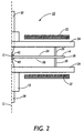
- Figures 2 and 3 show only one half of the spinner 10, as cut through the rotating shaft 12 and the liquid feed nozzles 28, 30 on centerline C.
- Figures 2 and 3 illustrate the operating characteristics of the spinner 10.
- Two streams of a hardenable liquid material 40, 42 are dispensed through liquid feed nozzles 28, 30 whose ends direct the hardenable liquid material 40, 42 to the separator member center Sc on each of the surfaces 34, 36 as shown in Figure 2.
- the hardenable liquid material 40, 42 then begins to flow out onto the surfaces 34, 36 of the separator member 14.
- the hardenable liquid material 40, 42 then flows to the ends of the surfaces 34, 36 and over the edge 38 where they form an outboard reservoir of liquid material.
- By controlling the dispensing rate of each it is possible to substantially equalize the flow rate at which the hardenable liquid materials 40, 42 reach the edge region 38, thus enabling the reservoir to include substantially equal amounts of each of the hardenable liquid materials 40, 42.
- the hardenable liquid materials 40, 42 adhere to each other but do not intermix, so that the reservoir includes side-by-side portions of each hardenable liquid material 40, 42. If the flow rates of the of the hardenable liquid materials 40, 42 are not substantially equal then although a reservoir will still be formed it will not include substantially equal amounts of each of the hardenable liquid materials 40, 42. The resulting bichromal elements will not have roughly hemispheric portions of each of the hardenable materials but one material will comprise a portion larger than hemispheric while the other material will comprise a portion smaller than hemispheric. When the rate of flow of the liquids away from the edge 38, into the host fluid (air is shown), is great enough, free jets 44 are formed as shown in Figure 3. However, we want the flow rates to be substantially equal.
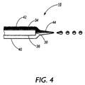
- Each jet 44 comprises a ligament of liquid fed by the reservoir at its originating end and breaking up into side-by-side substantially bichromal spheres at its distal end as shown in Figure 4. As the substantially bichromal spheres continue in their flight, they harden and drop under the influence of gravity, and are finally collected.
- liquid feed nozzles 28, 30 supply the hardenable liquid materials 42, 44 at greater distances from the separator member center Sc then the surfaces 34, 36 will not wet uniformly but will show a spiral pattern from the separator member center Sc outward which will interfere with proper substantially bichromal sphere production.
- Liquid flowing over the edge of the separator member 14 tends to form an outboard reservoir in the form of a ring of non-uniform diameter.
- This ring moves at the same speed as the separator member 14 and has circumferential protrusions, known as "Taylor instabilities", caused by the centrifugal force acting against surface tension.
- Tylor instabilities caused by the centrifugal force acting against surface tension.
- the protrusions or ligaments are formed.
- each ligament starts to peak, and finally will release a large droplet of the liquid which is attached to the ligament. Finally, the large drop breaks away followed by smaller droplets.
- a relatively stable steady state condition then exists, with liquid being fed into the reservoir and into the ligaments, and substantially uniform droplets being ejected into the host fluid from the distal ends of the ligaments.
- This inertial structure of spinning ligaments trailing the separator member 14 is held together by surface tension, which also causes their distal ends to be unstable and to break up into droplets. It is not necessary that the circumference of the separator member 14 be regular. In fact, a circumferential toothed structure will cause the "Taylor instabilities" and the resultant ligaments to be located coincident with each tooth. This allows a tailoring of the ligament structure and some added control over the size of the substantially bichromal spheres.
- the hardenable liquids 42, 44 are first deposited at the separator member center Sc associated with each surface 34, 36.
- the separator member 14 has a separator member thickness t which is small enough to ensure combining of the two streams of the hardenable liquid materials 34, 36 into a reservoir. If the separator member thickness t is too large, the hardenable liquid materials 40, 42 will not combine at the edge region 38 and only monochromal spheres will be produced. For example, a 3 inch diameter disk shaped separator member 14 rotated at about 2600 to 3000 rpm, a separator member thickness t of approximately less than 30 mils is desired. If the separator member is rotated at faster speeds, then a separator member thickness t of less is desired while if the separator member 14 is rotated at slower speeds than a separator member thickness t which is greater may be tolerated.
- the hardenable liquids may be delivered to separator members in a heated, molten state.
- the waxes should be delivered at a temperature of about 110 degrees C. This is so that the hardenable liquids may flow freely and do not harden prematurely, i.e. long enough to prevent the ligaments from freezing.
- four heating sources 32 are placed in proximity to the separator member 14. Several types of heating sources 32 are suitable, for example, an induction heater, a radiant shroud heater, or a clam-shell type heating structure surrounding the separator member 14 may all be used. While heating the separator member 14 is important to prevent premature hardening of the hardenable liquids, it must be noted that the heating should be confined to the area immediately surrounding the separator member 14 or hardening of the spheres may be delayed or prevented.
- a significant decrease in yield of substantially hemispherical bichromal spheres can be caused due to a spiraling of the ligaments. This problem is attributed to air turbulence and differential air flow caused by the effects of wind resistance at the edge of the disk, because the air adjacent to the disk is moving at a different velocity than the ligaments. Furthermore the air can be turbulent in this region.
- the rotating shrouds 24 prevent this problem, resulting in a greatly increased yield.
- the rotating shrouds 24 are mounted to the separator member 14 by rotating shroud support members 26, so that they are closely spaced from the surfaces of the separator member 14 and extend radially outwardly of the separator member 14.
- the substantially bichromal spheres should solidify as soon as possible after formation. Cooling may be accelerated by having the substantially bichromal spheres pass through a cooling zone. This has been accomplished experimentally by placing trays containing liquid nitrogen, beneath the spinning separator member 14 so that the substantially bichromal spheres move through the cold liquid nitrogen vapors shortly after being formed. This ensures hardening at the appropriate location.
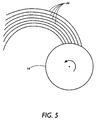
- high-viscosity hardenable liquids are used to create bichromal cylinders, If high-viscosity hardenable liquids are used the result is achieved as shown in Figure 5.
- the ligaments 44 formed by high-viscosity hardenable liquids do not break up into droplets but harden in place to form fine substantially cylindrical bichromal filaments. The filaments can then be aligned and separated into substantially bichromal cylinders.
Landscapes
- Physics & Mathematics (AREA)
- Chemical & Material Sciences (AREA)
- Health & Medical Sciences (AREA)
- Life Sciences & Earth Sciences (AREA)
- Molecular Biology (AREA)
- General Physics & Mathematics (AREA)
- Optics & Photonics (AREA)
- Organic Chemistry (AREA)
- Chemical Kinetics & Catalysis (AREA)
- Electrochromic Elements, Electrophoresis, Or Variable Reflection Or Absorption Elements (AREA)
- Treatment Of Fiber Materials (AREA)
Applications Claiming Priority (2)
| Application Number | Priority Date | Filing Date | Title |
|---|---|---|---|
| US36005299A | 1999-07-23 | 1999-07-23 | |
| US360052 | 1999-07-23 |
Publications (2)
| Publication Number | Publication Date |
|---|---|
| EP1070545A2 true EP1070545A2 (fr) | 2001-01-24 |
| EP1070545A3 EP1070545A3 (fr) | 2003-06-04 |
Family
ID=23416399
Family Applications (1)
| Application Number | Title | Priority Date | Filing Date |
|---|---|---|---|
| EP00115328A Withdrawn EP1070545A3 (fr) | 1999-07-23 | 2000-07-14 | Procédé et appareil de fabrication d'éléments bicolores |
Country Status (2)
| Country | Link |
|---|---|
| EP (1) | EP1070545A3 (fr) |
| JP (1) | JP2001066643A (fr) |
Cited By (1)
| Publication number | Priority date | Publication date | Assignee | Title |
|---|---|---|---|---|
| US7523546B2 (en) | 2005-05-04 | 2009-04-28 | Nokia Corporation | Method for manufacturing a composite layer for an electronic device |
Family Cites Families (4)
| Publication number | Priority date | Publication date | Assignee | Title |
|---|---|---|---|---|
| US5262098A (en) * | 1992-12-23 | 1993-11-16 | Xerox Corporation | Method and apparatus for fabricating bichromal balls for a twisting ball display |
| US5717514A (en) * | 1995-12-15 | 1998-02-10 | Xerox Corporation | Polychromal segmented balls for a twisting ball display |
| US5976428A (en) * | 1998-01-09 | 1999-11-02 | Xerox Corporation | Method and apparatus for controlling formation of two-color balls for a twisting ball display |
| US5900192A (en) * | 1998-01-09 | 1999-05-04 | Xerox Corporation | Method and apparatus for fabricating very small two-color balls for a twisting ball display |
-
2000
- 2000-07-14 JP JP2000214072A patent/JP2001066643A/ja not_active Withdrawn
- 2000-07-14 EP EP00115328A patent/EP1070545A3/fr not_active Withdrawn
Cited By (2)
| Publication number | Priority date | Publication date | Assignee | Title |
|---|---|---|---|---|
| US7523546B2 (en) | 2005-05-04 | 2009-04-28 | Nokia Corporation | Method for manufacturing a composite layer for an electronic device |
| US7881068B2 (en) | 2005-05-04 | 2011-02-01 | Nokia Corporation | Composite layer for an electronic device |
Also Published As
| Publication number | Publication date |
|---|---|
| JP2001066643A (ja) | 2001-03-16 |
| EP1070545A3 (fr) | 2003-06-04 |
Similar Documents
| Publication | Publication Date | Title |
|---|---|---|
| EP0604098B1 (fr) | Procédé et appareil pour la fabrication de boules bicolores pour un dispositif d'affichage par rotation de boules | |
| US5900192A (en) | Method and apparatus for fabricating very small two-color balls for a twisting ball display | |
| US6485280B1 (en) | Methods and apparatus for fabricating bichromal elements | |
| US4668267A (en) | Apparatus for the formation of mineral fibers by means of centrifuging wheels | |
| CA2257756C (fr) | Methode et appareil pour commander la formation de billes bicolores pour feuille d'affichage a billes orientables | |
| US5460498A (en) | Centrifugal spinning | |
| US5492463A (en) | Extrusion apparatus having a nozzle-headed drum | |
| SE441898B (sv) | Forfarande och anordning for elektrostatisk finfordelning av en vetska | |
| WO2004071614A2 (fr) | Procede et appareil de production de particules par traitement par fluide supercritique | |
| EP1070545A2 (fr) | Procédé et appareil de fabrication d'éléments bicolores | |
| US9056453B2 (en) | Droplet break-up device | |
| US4572100A (en) | Apparatus for moistening loose material | |
| US7232533B2 (en) | Bichromal element spinner | |
| JP4014239B2 (ja) | 微粉体の作製法 | |
| JP2003518431A (ja) | 回転ディスク上に均一厚さの液体又は溶融体の密着層を形成する方法及び装置 | |
| US2234521A (en) | Method and apparatus for producing glass filaments | |
| US7374797B2 (en) | Continuous combined pigmented wax compounding and bichromal sphere fabrication process | |
| CN1092077C (zh) | 差动双速旋转造粒机及造粒方法 | |
| KR20030031271A (ko) | 극세 금속섬유 제조장치 및 그 제조방법 | |
| JPS602095B2 (ja) | 熱軟化性物質のビ−ズの製造方法 | |
| JPS59123519A (ja) | 乳化液の製造装置 | |
| JPH0380957A (ja) | 回転霧化装置 | |
| JPS63169228A (ja) | 金属繊維の製造方法 | |
| JPH11290727A (ja) | 回転静電塗装機の塗料供給方法 |
Legal Events
| Date | Code | Title | Description |
|---|---|---|---|
| PUAI | Public reference made under article 153(3) epc to a published international application that has entered the european phase |
Free format text: ORIGINAL CODE: 0009012 |
|
| AK | Designated contracting states |
Kind code of ref document: A2 Designated state(s): AT BE CH CY DE DK ES FI FR GB GR IE IT LI LU MC NL PT SE |
|
| AX | Request for extension of the european patent |
Free format text: AL;LT;LV;MK;RO;SI |
|
| PUAL | Search report despatched |
Free format text: ORIGINAL CODE: 0009013 |
|
| AK | Designated contracting states |
Designated state(s): AT BE CH CY DE DK ES FI FR GB GR IE IT LI LU MC NL PT SE |
|
| AX | Request for extension of the european patent |
Extension state: AL LT LV MK RO SI |
|
| RIC1 | Information provided on ipc code assigned before grant |
Ipc: 7B 29B 9/10 B Ipc: 7B 01J 2/02 B Ipc: 7B 05B 3/10 A |
|
| STAA | Information on the status of an ep patent application or granted ep patent |
Free format text: STATUS: THE APPLICATION IS DEEMED TO BE WITHDRAWN |
|
| 18D | Application deemed to be withdrawn |
Effective date: 20030201 |