EP1070582B1 - Cylindre guide-feuilles pour une machine rotative - Google Patents
Cylindre guide-feuilles pour une machine rotative Download PDFInfo
- Publication number
- EP1070582B1 EP1070582B1 EP00114813A EP00114813A EP1070582B1 EP 1070582 B1 EP1070582 B1 EP 1070582B1 EP 00114813 A EP00114813 A EP 00114813A EP 00114813 A EP00114813 A EP 00114813A EP 1070582 B1 EP1070582 B1 EP 1070582B1
- Authority
- EP
- European Patent Office
- Prior art keywords
- cylinder
- sheet
- base body
- holding system
- gripper
- Prior art date
- Legal status (The legal status is an assumption and is not a legal conclusion. Google has not performed a legal analysis and makes no representation as to the accuracy of the status listed.)
- Expired - Lifetime
Links
- 238000012549 training Methods 0.000 description 5
- 238000012546 transfer Methods 0.000 description 4
- 230000013011 mating Effects 0.000 description 3
- 238000012545 processing Methods 0.000 description 2
- 238000010276 construction Methods 0.000 description 1
- 230000008878 coupling Effects 0.000 description 1
- 238000010168 coupling process Methods 0.000 description 1
- 238000005859 coupling reaction Methods 0.000 description 1
- 238000013461 design Methods 0.000 description 1
- 238000011161 development Methods 0.000 description 1
- 238000005461 lubrication Methods 0.000 description 1
- 238000012423 maintenance Methods 0.000 description 1
- 230000014759 maintenance of location Effects 0.000 description 1
- 238000004519 manufacturing process Methods 0.000 description 1
- 230000000149 penetrating effect Effects 0.000 description 1
- 238000000926 separation method Methods 0.000 description 1
- 238000011144 upstream manufacturing Methods 0.000 description 1
Images

Classifications
-
- B—PERFORMING OPERATIONS; TRANSPORTING
- B41—PRINTING; LINING MACHINES; TYPEWRITERS; STAMPS
- B41F—PRINTING MACHINES OR PRESSES
- B41F21/00—Devices for conveying sheets through printing apparatus or machines
- B41F21/10—Combinations of transfer drums and grippers
Definitions
- the invention relates to a sheet guide cylinder for a Rotary printing machine with at least one arranged on the circumference Sheet holding system for a sheet-shaped printing material.
- a sheet guide cylinder of this type is known from DD 53711, which is an interchangeable one, as a bow holding system trained closed unit as a gripper device having.
- the gripper device is on a carrier angled profile arranged directly in the cylinder channel.
- the angled girders form a structural unit with the gripper device, which with the cylinder channel wall by means of fastening screws is connected and to the cylinder channel pit with Set screws and pressure plate is adjustable.
- the turning drum consists of a body with trunnions at the ends and each an adjoining full cylindrical flange.
- a gripper device supports the sheet holding system Bearings on the base body and penetrates the end full cylindrical flanges.
- the turning drum has a drum surface, which as a removable Sheath element is formed.
- the sheet guide cylinder according to DD 53711 is a single-sized sheet guide cylinder, which can only be used on a single faceplate Gripper bridge limited. Furthermore, by inserting the gripper bridge into the cylinder channel the necessary Space for assembly and disassembly work restricted.
- the sheet guide cylinder according to DE 36 14 565 A1 shows the Flanges penetrating gripper shaft ends, so that the Assembly or disassembly of the sheet holding systems is complex.
- a sheet guide cylinder as Turning drum formed which two diametrically on the circumference has opposite sheet holding systems.
- Any bow holding system is by a suction system and two on top of each other swinging gripper systems formed.
- the bow holding systems are arranged directly on the base body and are with a corresponding control for the movement sequences in operative connection.
- a gripper shaft is for operation with a gripper system with grippers and an elevator tension shaft in bearings at the end.
- the bearings are detachably connected to the trapezoidal cutout by means of screws.
- a sheet transfer drum designed as a supporting body is included several gripper rows arranged symmetrically on the circumference are known.
- the rows of grabs are stored in bearing bodies and by means of these with the support body by means of screws connected.
- the invention is based on the object of a sheet guiding cylinder to create the type described above, the avoids mentioned disadvantages of a simple Assembly or disassembly of at least one of the sheet guide cylinders assigned bow holding system allowed and one improved access allowed.
- the task is based on the training features of the main claim solved. Further training results from the subclaims.
- a first advantage is due to the fact that a bow holding system is mountable on a board and that the board detachable with a cylinder base body having a surface connected is. This makes the board with the bow holding system as a unit easily assembled or disassembled and Adjustment and maintenance work are significantly reduced Effort realizable.
- the on a board Bow holding system with at least one cam roller depending on Requirement as gripping device or suction device or in Combination can be arranged and with at least one on the machine frame and / or the sheet guiding cylinder Control cam (cam gear) is in functional connection.
- gripping or suction devices are on one and the same Can be arranged so that it can be used for face printing or can be used for perfecting. So that's a thus designed sheet guide cylinder universal, for Example as a system drum, transfer cylinder, impression cylinder or can also be used as a turning unit.
- the sheet guiding cylinder as a single-size (single-turn) as well as a multi-size sheet-guiding cylinder (1/2-turn, 1/3-turn, 1/4-turn) - based on a single-size plate cylinder or forme cylinder - with the corresponding Number of boards with sheet holding systems is executable.
- a single circuit board with a bow holding system is arranged on a cylinder base body, or several boards with bow holding systems are arranged symmetrically on the circumference on a cylinder base body.
- each circuit board has at least one surface for receiving at least one sheet holding system on the top and at least one surface on the underside, which is functionally connected by means of at least one surface arranged on the basic cylinder body. These surfaces can be designed as a full surface or at least a partial surface in one plane or in different planes on the cylinder base body or to match the circuit board.
- the sheet guiding cylinder has a basic cylinder body with a cylinder axis. Symmetrical to The cylinder axis is at least one plane-parallel surface / partial surface on the cylinder body in at least one plane arranged.
- This surface / partial surface is an arch support system having circuit board with at least one on the underside arranged area / sub-area assigned, the Detachable with the cylinder body inside the Cylinder circumference is connected and the circuit board with it arranged bow support system at the mating point of Cam roller (with roller lever) and assigned control cam is separable from a cylinder body.
- a sheet-fed offset rotary printing press in Series construction is a sheet guiding cylinder between two printing units 4 arranged as a turning device.
- the first printing unit is arranged upstream a printing cylinder 1 as a sheet guide cylinder, a blanket cylinder 2 and a plate cylinder 3 formed.
- Analogous is the sheet guide cylinder 4 in the direction of sheet travel downstream second printing unit by a printing cylinder 1 as a sheet guide cylinder, a blanket cylinder 2 and a plate cylinder 3 is formed.
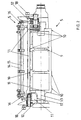
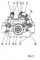
- a sheet guide cylinder 4 acc. Fig. 2 consists of a a cylinder axis 13 symmetrical cylinder body 9, which is preferred as a one-piece drum body with journal is executed.
- Within the drum circumference of the sheet guide cylinder 4 are several in relation to the cylinder axis 13 plane-parallel partial surfaces 10 as a support in one plane arranged for each a board 11 described in more detail.
- the partial areas 10 can be replaced by a full one Surface 10 can be formed as a support. 2 are about Width of the basic cylinder body 9 distributed four Subareas 10 shown.
- the cylinder body 9 likewise with only one appropriately dimensioned Partial surface 10 may be formed per board 11.
- partial surfaces 10 are symmetrical on the circumference each half of the sheet guide cylinder 4 by 180 ° staggered. With multiple arrangement of the sub-areas 10 align these plane-parallel to the cylinder axis 13 in each Half (with double-sized training) in at least one Level. 2 and 3 is for reasons of clarity only one arranged on the cylinder body 9 Board 11 shown with a sheet holding system 5.
- the sheet guide cylinder 4 as a turning device supports on the circumference on each half two diametrically offset 180 ° arranged sheet holding systems 5.
- a sheet holding system 5 consists in the present example of a suction system 8 with swiveling suction tube, a first gripper system 6 (counter pressure gripper) and a second gripper system 7 (fine-pressure gripper) with corresponding gripper shafts 14 with roller levers and cam rollers 18 and gripper pads and associated Control curves for the gripper shaft control.
- Any bow holding system 5 also has pivot shafts 15 with control cams for the corresponding swivel shaft control of the gripper systems 6, 7 and a movement mechanism, e.g. on Cam or coupling gear, for the suction system 8 to the transfer of the sheets between the sheet-guiding cylinders as well as the inner sheet transfers on the sheet guide cylinder 4 to realize yourself.
- Each sheet holding system 5 is completely based on that already mentioned Board 11 arranged in bearings 16 so that this Combination represents an assembly.
- Each board 11 is with the underside releasably with the partial surfaces 10 connected to the cylinder base body 9 and carries on both sides (in Axis direction of the sheet holding systems 5) at each end Side part 12, which is fixed to the circuit board 11 and at least partially the bearing points of the roller levers Pick up cam roller 18.
- the ones that carry the gripper systems 6,7 Swivel shafts 15 are rotatably received in the bearings 16, which is arranged on the top of the circuit board 11 are.
- the side parts 12 are either not detachable Example cast or welded, or preferably detachable, for example screwed, connected to the circuit board 11 and carry the control of the gripper systems 6, 7 and Suction system 8 and the swivel shafts 15, inclusive Cam rollers 18, which are then in a known manner via control curves (Cam mechanism) are controllable.
- At least one is preferred on the underside of the circuit board 11 are arranged several sub-areas 10, which on Cylinder base 9 arranged partial areas 10 adjacent assigned. Depending on the training, there is also a combination of full area 10 and partial areas 10 or of two full areas Surfaces 10 on the cylinder base body 9 or circuit board 11 can be realized.
- the partial surfaces 10 of the basic cylinder body 9 and Bottom of the board 11 are at least in one plane arranged.
- the circuit board 11 and / or the corresponding side part 12 in another Can be stored on the cylinder base 9. This also applies plane-parallel to the cylinder axis 13 one or more additional surfaces 17 can be arranged (Fig. 2).
- the additional surface 17 is there on the cylinder base body 9 and on the adjacent associated
- the underside of the circuit board 11 or the side part 12 is arranged.
- the board 11 is always within the cylinder circumference arranged and supported on the additional surfaces 17 if necessary from.
- the design described is not a double size Sheet guiding cylinder 4 with two circumferentially arranged Boards 11 with sheet holding systems 5 limited.
- this solution is also suitable for a cylinder base body 9, for example a single-sized sheet guiding cylinder 4, with only one plate 11 and one sheet holding system 5 on the circumference.
- triple or quadruple-sized sheet guiding cylinders 4 with a corresponding number of plates 11 arranged symmetrically on the circumference can also be designed with sheet holding systems 5.
- a sheet guiding cylinder 4 with a board 11 with sheet holding system 5 at least one surface or partial surface 10 is arranged on the cylinder base body 9, so that the circuit board 11 with the underside (surface or partial surface 10) is detachably fixed within the drum circumference.
- a plurality of surfaces or partial surfaces 10 are arranged symmetrically on the cylinder base body 9 by 120 ° (with three plates 11) or by 90 ° (with four plates 11) on the circumference, so that the Boards 11 with the underside (surface or partial surface 10) are releasably fixable on the cylinder base body 9 within the drum circumference.
- only one gripper system 7, for example as a straight-pressure gripper, with a mounted gripper shaft 14 and at least one cam roller 18 can be arranged on a circuit board 11.
- a first and a second gripper system 6, 7, each with gripper shaft 14 and associated cam rollers 18 with swivel shafts 15 (or a comparable swivel mechanism) and associated cam rollers 18 can be arranged on a circuit board 11.
- at least one stored suction system 8 with a corresponding movement mechanism and associated cam roller 18 can be arranged.
- the cam rollers 18 are in turn functionally connected to control cams.
- the sheet holding system 5 is formed at least by a gripper system 6 and / or 7, at least one gripper system 6, 7 being separable from the cylinder base body 9 at the mating point of the associated cam roller 18 and associated control cam.
- this sheet holding system 5 has at least one suction system 8, the suction systems 8 being separable from the cylinder base body 9 at the mating points of the cam roller 18 and the associated control cam.
Landscapes
- Feeding Of Articles By Means Other Than Belts Or Rollers (AREA)
- Supply, Installation And Extraction Of Printed Sheets Or Plates (AREA)
- Registering, Tensioning, Guiding Webs, And Rollers Therefor (AREA)
- Rotary Presses (AREA)
Claims (6)
- Cylindre de guidage de feuilles (4) pour une machine d'impression rotative, comportant un système de maintien de feuilles (5) agencé à la périphérie de façon échangeable ayant un galet de came (18) et une came de commande associée pour les déplacements, le cylindre de guidage de feuilles (4) présentant un corps de base de cylindre (9) ayant un axe de cylindre (13) et, par rapport à l'axe de cylindre (13), une surface/surface partielle (10) agencée dans un plan, parallèle et plane, un flan (11) présentant sur le dessus au moins un système de maintien de feuilles (5) étant agencé de façon amovible sur cette surface/surface partielle (10) avec le dessous à l'intérieur de la périphérie du cylindre et chaque système de maintien de feuilles (5) pouvant être séparé du corps de base du cylindre (9) à l'endroit d'appariement du galet de came (18) et de la came de commande associée.
- Cylindre de guidage de feuilles selon la revendication 1,
caractérisé en ce que le corps de base du cylindre (9) présente, de façon périphérique, symétriquement par rapport à l'axe du cylindre (13), plusieurs surfaces/surfaces partielles (10) planes et parallèles, et en ce que, sur chaque surface/surface partielle (10), il est agencé, à chaque fois, de façon amovible, un flan (11) présentant au moins un système de maintien de feuilles (5) avec le dessous à l'intérieur de la périphérie du cylindre. - Cylindre de guidage de feuilles selon la revendication 1,
caractérisé en ce que le système de maintien de feuilles (5) présente au moins un système de pinces (6, 7), les systèmes de pinces (6, 7) pouvant être séparés du corps de base du cylindre (9), à chaque fois, au niveau d'un endroit d'appariement du galet de came (18) et de la came de commande associée. - Cylindre de guidage de feuilles selon la revendication 1,
caractérisé en ce que le système de maintien de feuilles (5) présente au moins un système d'aspiration (8), les systèmes d'aspiration (8) pouvant être séparés du corps de base du cylindre (9), à chaque fois, au niveau d'un endroit d'appariement du galet de came (18) et de la came de commande associée. - Cylindre de guidage de feuilles selon au moins la revendication 1,
caractérisé en ce que, sur le flan (11), des parties latérales (12) sont agencées des deux côtés en direction axiale des systèmes de maintien de feuilles à chaque fois du côté d'extrémité, lesquelles reçoivent les points d'appui des leviers à galet de came (18). - Cylindre de guidage de feuilles selon au moins les revendications 1 et 5,
caractérisé en ce que le corps de base du cylindre (9) présente au moins une surface supplémentaire (17) agencée de façon parallèle et plane par rapport à l'axe du cylindre (13), sur laquelle le dessous du flan (11) et/ou de la partie latérale (12) peut s'appuyer de façon supplémentaire à l'intérieur de la périphérie du cylindre.
Applications Claiming Priority (2)
| Application Number | Priority Date | Filing Date | Title |
|---|---|---|---|
| DE19934526 | 1999-07-22 | ||
| DE19934526A DE19934526A1 (de) | 1999-07-22 | 1999-07-22 | Bogenführungszylinder für eine Rotationsdruckmaschine |
Publications (2)
| Publication Number | Publication Date |
|---|---|
| EP1070582A1 EP1070582A1 (fr) | 2001-01-24 |
| EP1070582B1 true EP1070582B1 (fr) | 2003-05-21 |
Family
ID=7915763
Family Applications (1)
| Application Number | Title | Priority Date | Filing Date |
|---|---|---|---|
| EP00114813A Expired - Lifetime EP1070582B1 (fr) | 1999-07-22 | 2000-07-11 | Cylindre guide-feuilles pour une machine rotative |
Country Status (4)
| Country | Link |
|---|---|
| EP (1) | EP1070582B1 (fr) |
| JP (1) | JP3410066B2 (fr) |
| AT (1) | ATE240836T1 (fr) |
| DE (2) | DE19934526A1 (fr) |
Family Cites Families (8)
| Publication number | Priority date | Publication date | Assignee | Title |
|---|---|---|---|---|
| DD53711A (fr) * | ||||
| DE191658C (fr) * | ||||
| DD110452A1 (fr) * | 1974-03-21 | 1974-12-20 | ||
| DE3267440D1 (en) * | 1981-09-04 | 1985-12-19 | Motter Printing Press Co | Gripper for sheet handling equipment |
| DE3428668A1 (de) * | 1984-08-03 | 1986-02-13 | Heidelberger Druckmaschinen Ag, 6900 Heidelberg | Umfuehrtrommel fuer bogendruckmaschinen, insbesondere kartonmaschinen |
| DE3602084A1 (de) * | 1986-01-24 | 1987-07-30 | Heidelberger Druckmasch Ag | Bogenueberfuehrtrommel zwischen den druckwerken von rotationsdruckmaschinen |
| DE3614565A1 (de) * | 1986-04-29 | 1987-11-05 | Roland Man Druckmasch | Wendetrommel in bogenrotationsdruckmaschinen |
| DE19650012A1 (de) * | 1996-12-03 | 1998-06-04 | Kba Planeta Ag | Greiferbetätigungssystem |
-
1999
- 1999-07-22 DE DE19934526A patent/DE19934526A1/de not_active Ceased
-
2000
- 2000-07-11 EP EP00114813A patent/EP1070582B1/fr not_active Expired - Lifetime
- 2000-07-11 AT AT00114813T patent/ATE240836T1/de not_active IP Right Cessation
- 2000-07-11 DE DE50002241T patent/DE50002241D1/de not_active Expired - Lifetime
- 2000-07-21 JP JP2000221417A patent/JP3410066B2/ja not_active Expired - Fee Related
Also Published As
| Publication number | Publication date |
|---|---|
| EP1070582A1 (fr) | 2001-01-24 |
| ATE240836T1 (de) | 2003-06-15 |
| JP2001063000A (ja) | 2001-03-13 |
| DE50002241D1 (de) | 2003-06-26 |
| JP3410066B2 (ja) | 2003-05-26 |
| DE19934526A1 (de) | 2001-02-08 |
Similar Documents
| Publication | Publication Date | Title |
|---|---|---|
| EP3043994B1 (fr) | Machine à imprimer pour impression de papiers-valeur et procédé pour remplacer une forme imprimante et pour démarrage de la presse | |
| DE10156800B4 (de) | Druckwerk | |
| EP3043997B1 (fr) | Procédé et dispositif pour régler des corps rotatifs de transport d'encre d'une machine à imprimer | |
| EP0290853A2 (fr) | Palier pour cylindre de groupe d'impression | |
| DE9116367U1 (de) | Zylinder für die Papierführung an Bogenrotationsdruckmaschinen | |
| EP1511631B1 (fr) | Systeme d'encrage pour des presses flexographiques | |
| DE102013214784B4 (de) | Vorrichtung zum Korrigieren trapezartiger Passerabweichungen | |
| EP0924069B1 (fr) | Dispositif de guidage de feuilles dans une machine à imprimer | |
| EP1070582B1 (fr) | Cylindre guide-feuilles pour une machine rotative | |
| EP0243737A2 (fr) | Cylindre de retournement pour machine rotative à imprimer des feuilles | |
| EP0085752B1 (fr) | Groupe imprimant pour rotative offset | |
| DE10035354B4 (de) | Offsetdruckmaschine | |
| DE3880697T2 (de) | Farbvorrichtung fuer druckmaschine. | |
| DE19954390C1 (de) | Pneumatische Bogenführungseinrichtung in einer Druckmaschine | |
| DE4433999C2 (de) | Bogenführende Trommel für Rotationsdruckmaschinen | |
| EP1710081A2 (fr) | Machine d'impression, en particulier machine d'impression de feuilles | |
| DE2926765A1 (de) | Vorrichtung zur unterdrueckung von biegeschwingungen in rotations-offsetdruckmaschinen | |
| DE2945192C2 (de) | Offsetdruckmaschine | |
| DE19854053A1 (de) | Bogenführungseinrichtung für eine Druckmaschine | |
| DE10119140A1 (de) | Bedruckstoffbögen verarbeitende Maschine | |
| EP1732760B1 (fr) | Groupe d'impression de machine a imprimer, muni d'un rouleau presseur | |
| DE19941633A1 (de) | Verfahren und Einrichtung zum Einstellen und Wechseln von Saugringen | |
| DE10347153B4 (de) | Verfahren zum Umstellen der Bewegung eines Bogenhaltesystems in einer Verarbeitungsmaschine | |
| DE1159471B (de) | Vorrichtung zum Einstellen auf unterschiedliche Bogenstaerken bei einer Rotationsbogendruckmaschine fuer Mehrfarbendruck | |
| EP1005982A1 (fr) | Dispositif pour échanger des rouleaux ou cylindres dans une machine à imprimer |
Legal Events
| Date | Code | Title | Description |
|---|---|---|---|
| PUAI | Public reference made under article 153(3) epc to a published international application that has entered the european phase |
Free format text: ORIGINAL CODE: 0009012 |
|
| AK | Designated contracting states |
Kind code of ref document: A1 Designated state(s): AT BE CH CY DE DK ES FI FR GB GR IE IT LI LU MC NL PT SE |
|
| AX | Request for extension of the european patent |
Free format text: AL;LT;LV;MK;RO;SI |
|
| 17P | Request for examination filed |
Effective date: 20001206 |
|
| 17Q | First examination report despatched |
Effective date: 20010802 |
|
| AKX | Designation fees paid |
Free format text: AT BE CH CY DE DK ES FI FR GB GR IE IT LI LU MC NL PT SE |
|
| GRAH | Despatch of communication of intention to grant a patent |
Free format text: ORIGINAL CODE: EPIDOS IGRA |
|
| GRAH | Despatch of communication of intention to grant a patent |
Free format text: ORIGINAL CODE: EPIDOS IGRA |
|
| GRAA | (expected) grant |
Free format text: ORIGINAL CODE: 0009210 |
|
| AK | Designated contracting states |
Designated state(s): AT BE CH CY DE DK ES FI FR GB GR IE IT LI LU MC NL PT SE |
|
| PG25 | Lapsed in a contracting state [announced via postgrant information from national office to epo] |
Ref country code: IT Free format text: LAPSE BECAUSE OF FAILURE TO SUBMIT A TRANSLATION OF THE DESCRIPTION OR TO PAY THE FEE WITHIN THE PRESCRIBED TIME-LIMIT;WARNING: LAPSES OF ITALIAN PATENTS WITH EFFECTIVE DATE BEFORE 2007 MAY HAVE OCCURRED AT ANY TIME BEFORE 2007. THE CORRECT EFFECTIVE DATE MAY BE DIFFERENT FROM THE ONE RECORDED. Effective date: 20030521 Ref country code: IE Free format text: LAPSE BECAUSE OF NON-PAYMENT OF DUE FEES Effective date: 20030521 Ref country code: NL Free format text: LAPSE BECAUSE OF FAILURE TO SUBMIT A TRANSLATION OF THE DESCRIPTION OR TO PAY THE FEE WITHIN THE PRESCRIBED TIME-LIMIT Effective date: 20030521 Ref country code: FI Free format text: LAPSE BECAUSE OF FAILURE TO SUBMIT A TRANSLATION OF THE DESCRIPTION OR TO PAY THE FEE WITHIN THE PRESCRIBED TIME-LIMIT Effective date: 20030521 Ref country code: FR Free format text: LAPSE BECAUSE OF NON-PAYMENT OF DUE FEES Effective date: 20030521 |
|
| REG | Reference to a national code |
Ref country code: GB Ref legal event code: FG4D Free format text: NOT ENGLISH |
|
| REG | Reference to a national code |
Ref country code: CH Ref legal event code: EP |
|
| GBT | Gb: translation of ep patent filed (gb section 77(6)(a)/1977) |
Effective date: 20030521 |
|
| REG | Reference to a national code |
Ref country code: IE Ref legal event code: FG4D Free format text: GERMAN |
|
| REF | Corresponds to: |
Ref document number: 50002241 Country of ref document: DE Date of ref document: 20030626 Kind code of ref document: P |
|
| PG25 | Lapsed in a contracting state [announced via postgrant information from national office to epo] |
Ref country code: LU Free format text: LAPSE BECAUSE OF NON-PAYMENT OF DUE FEES Effective date: 20030711 Ref country code: CY Free format text: LAPSE BECAUSE OF FAILURE TO SUBMIT A TRANSLATION OF THE DESCRIPTION OR TO PAY THE FEE WITHIN THE PRESCRIBED TIME-LIMIT Effective date: 20030711 |
|
| PG25 | Lapsed in a contracting state [announced via postgrant information from national office to epo] |
Ref country code: BE Free format text: LAPSE BECAUSE OF NON-PAYMENT OF DUE FEES Effective date: 20030731 Ref country code: MC Free format text: LAPSE BECAUSE OF NON-PAYMENT OF DUE FEES Effective date: 20030731 |
|
| PG25 | Lapsed in a contracting state [announced via postgrant information from national office to epo] |
Ref country code: DK Free format text: LAPSE BECAUSE OF FAILURE TO SUBMIT A TRANSLATION OF THE DESCRIPTION OR TO PAY THE FEE WITHIN THE PRESCRIBED TIME-LIMIT Effective date: 20030821 Ref country code: SE Free format text: LAPSE BECAUSE OF FAILURE TO SUBMIT A TRANSLATION OF THE DESCRIPTION OR TO PAY THE FEE WITHIN THE PRESCRIBED TIME-LIMIT Effective date: 20030821 Ref country code: PT Free format text: LAPSE BECAUSE OF FAILURE TO SUBMIT A TRANSLATION OF THE DESCRIPTION OR TO PAY THE FEE WITHIN THE PRESCRIBED TIME-LIMIT Effective date: 20030821 Ref country code: GR Free format text: LAPSE BECAUSE OF FAILURE TO SUBMIT A TRANSLATION OF THE DESCRIPTION OR TO PAY THE FEE WITHIN THE PRESCRIBED TIME-LIMIT Effective date: 20030821 |
|
| PG25 | Lapsed in a contracting state [announced via postgrant information from national office to epo] |
Ref country code: ES Free format text: LAPSE BECAUSE OF FAILURE TO SUBMIT A TRANSLATION OF THE DESCRIPTION OR TO PAY THE FEE WITHIN THE PRESCRIBED TIME-LIMIT Effective date: 20030901 |
|
| NLV1 | Nl: lapsed or annulled due to failure to fulfill the requirements of art. 29p and 29m of the patents act | ||
| REG | Reference to a national code |
Ref country code: IE Ref legal event code: FD4D Ref document number: 1070582E Country of ref document: IE |
|
| BERE | Be: lapsed |
Owner name: *MAN ROLAND DRUCKMASCHINEN A.G. Effective date: 20030731 |
|
| PLBE | No opposition filed within time limit |
Free format text: ORIGINAL CODE: 0009261 |
|
| STAA | Information on the status of an ep patent application or granted ep patent |
Free format text: STATUS: NO OPPOSITION FILED WITHIN TIME LIMIT |
|
| 26N | No opposition filed |
Effective date: 20040224 |
|
| EN | Fr: translation not filed | ||
| PG25 | Lapsed in a contracting state [announced via postgrant information from national office to epo] |
Ref country code: GB Free format text: LAPSE BECAUSE OF NON-PAYMENT OF DUE FEES Effective date: 20040711 |
|
| PG25 | Lapsed in a contracting state [announced via postgrant information from national office to epo] |
Ref country code: CH Free format text: LAPSE BECAUSE OF NON-PAYMENT OF DUE FEES Effective date: 20040731 Ref country code: LI Free format text: LAPSE BECAUSE OF NON-PAYMENT OF DUE FEES Effective date: 20040731 |
|
| GBPC | Gb: european patent ceased through non-payment of renewal fee |
Effective date: 20040711 |
|
| REG | Reference to a national code |
Ref country code: CH Ref legal event code: PL |
|
| PGFP | Annual fee paid to national office [announced via postgrant information from national office to epo] |
Ref country code: AT Payment date: 20080715 Year of fee payment: 9 |
|
| PG25 | Lapsed in a contracting state [announced via postgrant information from national office to epo] |
Ref country code: AT Free format text: LAPSE BECAUSE OF NON-PAYMENT OF DUE FEES Effective date: 20090711 |
|
| PGFP | Annual fee paid to national office [announced via postgrant information from national office to epo] |
Ref country code: DE Payment date: 20110722 Year of fee payment: 12 |
|
| REG | Reference to a national code |
Ref country code: DE Ref legal event code: R081 Ref document number: 50002241 Country of ref document: DE Owner name: MANROLAND SHEETFED GMBH, DE Free format text: FORMER OWNER: MANROLAND AG, 63075 OFFENBACH, DE Effective date: 20120509 |
|
| PG25 | Lapsed in a contracting state [announced via postgrant information from national office to epo] |
Ref country code: DE Free format text: LAPSE BECAUSE OF NON-PAYMENT OF DUE FEES Effective date: 20130201 |
|
| REG | Reference to a national code |
Ref country code: DE Ref legal event code: R119 Ref document number: 50002241 Country of ref document: DE Effective date: 20130201 |