EP1070603A2 - Assemblage de retenue pour moyeu d'essieu et ensemble palier - Google Patents
Assemblage de retenue pour moyeu d'essieu et ensemble palier Download PDFInfo
- Publication number
- EP1070603A2 EP1070603A2 EP00114983A EP00114983A EP1070603A2 EP 1070603 A2 EP1070603 A2 EP 1070603A2 EP 00114983 A EP00114983 A EP 00114983A EP 00114983 A EP00114983 A EP 00114983A EP 1070603 A2 EP1070603 A2 EP 1070603A2
- Authority
- EP
- European Patent Office
- Prior art keywords
- washer
- assembly
- spindle
- end nut
- set forth
- Prior art date
- Legal status (The legal status is an assumption and is not a legal conclusion. Google has not performed a legal analysis and makes no representation as to the accuracy of the status listed.)
- Withdrawn
Links
- 230000000712 assembly Effects 0.000 description 4
- 238000000429 assembly Methods 0.000 description 4
- 230000004048 modification Effects 0.000 description 1
- 238000012986 modification Methods 0.000 description 1
- 230000000149 penetrating effect Effects 0.000 description 1
Images


Classifications
-
- B—PERFORMING OPERATIONS; TRANSPORTING
- B60—VEHICLES IN GENERAL
- B60B—VEHICLE WHEELS; CASTORS; AXLES FOR WHEELS OR CASTORS; INCREASING WHEEL ADHESION
- B60B27/00—Hubs
- B60B27/02—Hubs adapted to be rotatably arranged on axle
-
- F—MECHANICAL ENGINEERING; LIGHTING; HEATING; WEAPONS; BLASTING
- F16—ENGINEERING ELEMENTS AND UNITS; GENERAL MEASURES FOR PRODUCING AND MAINTAINING EFFECTIVE FUNCTIONING OF MACHINES OR INSTALLATIONS; THERMAL INSULATION IN GENERAL
- F16C—SHAFTS; FLEXIBLE SHAFTS; ELEMENTS OR CRANKSHAFT MECHANISMS; ROTARY BODIES OTHER THAN GEARING ELEMENTS; BEARINGS
- F16C25/00—Bearings for exclusively rotary movement adjustable for wear or play
- F16C25/06—Ball or roller bearings
-
- F—MECHANICAL ENGINEERING; LIGHTING; HEATING; WEAPONS; BLASTING
- F16—ENGINEERING ELEMENTS AND UNITS; GENERAL MEASURES FOR PRODUCING AND MAINTAINING EFFECTIVE FUNCTIONING OF MACHINES OR INSTALLATIONS; THERMAL INSULATION IN GENERAL
- F16C—SHAFTS; FLEXIBLE SHAFTS; ELEMENTS OR CRANKSHAFT MECHANISMS; ROTARY BODIES OTHER THAN GEARING ELEMENTS; BEARINGS
- F16C35/00—Rigid support of bearing units; Housings, e.g. caps, covers
- F16C35/04—Rigid support of bearing units; Housings, e.g. caps, covers in the case of ball or roller bearings
- F16C35/06—Mounting or dismounting of ball or roller bearings; Fixing them onto shaft or in housing
- F16C35/067—Fixing them in a housing
-
- F—MECHANICAL ENGINEERING; LIGHTING; HEATING; WEAPONS; BLASTING
- F16—ENGINEERING ELEMENTS AND UNITS; GENERAL MEASURES FOR PRODUCING AND MAINTAINING EFFECTIVE FUNCTIONING OF MACHINES OR INSTALLATIONS; THERMAL INSULATION IN GENERAL
- F16C—SHAFTS; FLEXIBLE SHAFTS; ELEMENTS OR CRANKSHAFT MECHANISMS; ROTARY BODIES OTHER THAN GEARING ELEMENTS; BEARINGS
- F16C19/00—Bearings with rolling contact, for exclusively rotary movement
- F16C19/22—Bearings with rolling contact, for exclusively rotary movement with bearing rollers essentially of the same size in one or more circular rows, e.g. needle bearings
- F16C19/34—Bearings with rolling contact, for exclusively rotary movement with bearing rollers essentially of the same size in one or more circular rows, e.g. needle bearings for both radial and axial load
- F16C19/38—Bearings with rolling contact, for exclusively rotary movement with bearing rollers essentially of the same size in one or more circular rows, e.g. needle bearings for both radial and axial load with two or more rows of rollers
- F16C19/383—Bearings with rolling contact, for exclusively rotary movement with bearing rollers essentially of the same size in one or more circular rows, e.g. needle bearings for both radial and axial load with two or more rows of rollers with tapered rollers, i.e. rollers having essentially the shape of a truncated cone
- F16C19/385—Bearings with rolling contact, for exclusively rotary movement with bearing rollers essentially of the same size in one or more circular rows, e.g. needle bearings for both radial and axial load with two or more rows of rollers with tapered rollers, i.e. rollers having essentially the shape of a truncated cone with two rows, i.e. double-row tapered roller bearings
- F16C19/386—Bearings with rolling contact, for exclusively rotary movement with bearing rollers essentially of the same size in one or more circular rows, e.g. needle bearings for both radial and axial load with two or more rows of rollers with tapered rollers, i.e. rollers having essentially the shape of a truncated cone with two rows, i.e. double-row tapered roller bearings in O-arrangement
-
- F—MECHANICAL ENGINEERING; LIGHTING; HEATING; WEAPONS; BLASTING
- F16—ENGINEERING ELEMENTS AND UNITS; GENERAL MEASURES FOR PRODUCING AND MAINTAINING EFFECTIVE FUNCTIONING OF MACHINES OR INSTALLATIONS; THERMAL INSULATION IN GENERAL
- F16C—SHAFTS; FLEXIBLE SHAFTS; ELEMENTS OR CRANKSHAFT MECHANISMS; ROTARY BODIES OTHER THAN GEARING ELEMENTS; BEARINGS
- F16C2326/00—Articles relating to transporting
- F16C2326/01—Parts of vehicles in general
- F16C2326/02—Wheel hubs or castors
-
- F—MECHANICAL ENGINEERING; LIGHTING; HEATING; WEAPONS; BLASTING
- F16—ENGINEERING ELEMENTS AND UNITS; GENERAL MEASURES FOR PRODUCING AND MAINTAINING EFFECTIVE FUNCTIONING OF MACHINES OR INSTALLATIONS; THERMAL INSULATION IN GENERAL
- F16C—SHAFTS; FLEXIBLE SHAFTS; ELEMENTS OR CRANKSHAFT MECHANISMS; ROTARY BODIES OTHER THAN GEARING ELEMENTS; BEARINGS
- F16C35/00—Rigid support of bearing units; Housings, e.g. caps, covers
- F16C35/04—Rigid support of bearing units; Housings, e.g. caps, covers in the case of ball or roller bearings
- F16C35/06—Mounting or dismounting of ball or roller bearings; Fixing them onto shaft or in housing
- F16C35/063—Fixing them on the shaft
Definitions
- This invention relates to an axle assembly for supporting wheels and, more specifically, to a retaining assembly used to retain a hub assembly and bearing assembly onto a spindle of the axle assembly.
- Axle assemblies support wheels on their distal ends, or spindles. Hub assemblies, which carry the wheels, are supported on the spindles by bearing assemblies. Typically, end nuts are fastened to the spindles to secure the bearing and hub assemblies to the spindle.
- An additional retaining device is usually employed to ensure that the end nut does not come unfastened from the spindle.
- a split pin may be installed in a hole transverse to the spindle axis and adjacent to the end nut. However, if the hole and pin are not precisely placed relative to the location of the installed end nut, the pin will be difficult to install or will allow the nut to loosen until it contacts the pin. Therefore, what is needed is a retaining device that prevents the end nut from loosening from its originally installed location.
- the present invention provides an axle assembly for supporting wheels that has a spindle defining an axis of rotation with a threaded end portion.
- a hub assembly is supported by the spindle and is adapted to support the wheels.
- a bearing assembly is arranged adjacent to the threaded end portion and is interposed between the spindle and the hub assembly for permitting low friction rotation of the hub assembly relative to the spindle about the axis.
- An end nut is secured to the threaded end portion of the spindle for retaining the bearing assembly and the hub assembly on the spindle.
- a washer is interposed between said bearing assembly and the end nut wherein the washer secures the end nut to the spindle for preventing rotation of the end nut about the axis.
- the above provides an improved mechanism for retaining the hub assembly and bearing assembly on the spindle of an axle assembly.
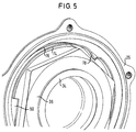
- an axle assembly 20 has an axle housing 22 with a spindle 24 at each of its distal ends.
- the spindle 24 defines an axis of rotation, A, about which a hub assembly 26 rotates.
- the hub assembly 26 is supported by the spindle 24 and is adapted to support the wheels 28.
- the hub assembly 26 also supports a brake drum 30, or a rotor for disc brakes (not shown).
- a bearing assembly 32 is arranged between the spindle 24 and hub assembly 26 to permit low friction rotation of the hub assembly 26 about the axis A.
- the spindle 24 has a threaded end portion 34 adjacent to the bearing assembly 32 with an end nut 38 fastened to the threaded end portion 34 for retaining the bearing assembly 32 and hub assembly 26 on the spindle 24.
- a hub cap 39 is secured to the hub assembly 26 to seal the bearing assembly 32 from the outside environment.
- a washer assembly 42 is arranged between the bearing assembly 32 and the end nut 38.
- the washer assembly 42 secures the end nut 38 to the spindle 24 for preventing rotation of the end nut 38 about the axis A, which is described in more detail below.
- the bearing assembly 32 or bearing cartridge, has a two piece cone 44 press fit onto the spindle 24 and a cup 46 press fit into an interior surface 47 of the hub assembly 26.
- Roller bearings 48 are arranged radially between the cone 44 and cup 46 and are located relative to one another by a cage 50.
- Seals 52 are arranged between the cone 44 and cup 46 at the outer ends of the bearing assembly 32 to prevent debris from penetrating the bearing assembly 32.
- the hub assembly 32 has a groove 54 on the interior surface 47 adjacent to the cup 46.
- a C-shaped retaining clip 56 is seated in the groove 54 to retain the bearing assembly 32 in the hub assembly 26 and prevent movement of the bearing assembly 32 along the axis A.
- the retaining clip 56 which has a circular cross-section, is larger than the groove 54 so that the retaining clip 56 must be compressed to insert the clip 56 into the groove 54.
- the end nut 38 is prevented from loosening by rotating about the axis A.
- the washer assembly 42 is secured to the spindle 24 and the end nut 38.
- the washer assembly 42 includes a locating washer 62 and a staking washer 64 that are secured to one another.
- the locating washer 62 engages a groove 60 in the spindle 24 that is generally parallel with the axis A, and the staking washer 64 is deformed into engagement with the end nut 38.
- the locating washer 62 has a first inner diameter 65 with a tab 66 that extends radially inwardly from the first inner diameter 65 and engages the groove 60 thereby preventing the washer assembly 42 from rotating about the spindle 24.
- the staking washer 64 includes a second inner diameter 69 with at least one prong 70 extending transversely from the second inner diameter 69.
- the locating washer 62 has at least one notch 68 that receives a corresponding prong 70 for securing the locating 62 and staking 64 washers together.
- the prongs 70 may be bent outward from the inner diameter 69 to ensure that the washers 62, 64 are secured together.
- the staking washer 64 has an outer diameter 72 with an arcuate flange 74 extending transversely from the outer diameter 72, best shown in Figures 8 and 9.
- the end nut 38 has an outer perimeter 76 adjacent to the arcuate flange 74.
- the end nut 38 has at least one recess 80.
- a portion 78 of the flange 74 is deformed into engagement with the recess 80 of the end nut 38, preferably so that the portion 78 shears and the portion 78 abuts the recess 80 to ensure that the end nut 38 cannot rotate relative to the washer assembly 42.
- the end nut 38 has three recesses 80 disposed radially about the end nut 38 with the flange 74 deformed into engagement with only one recess 80.
Landscapes
- Engineering & Computer Science (AREA)
- General Engineering & Computer Science (AREA)
- Mechanical Engineering (AREA)
- Mounting Of Bearings Or Others (AREA)
- Rolling Contact Bearings (AREA)
Applications Claiming Priority (2)
| Application Number | Priority Date | Filing Date | Title |
|---|---|---|---|
| US359236 | 1989-05-31 | ||
| US09/359,236 US6224167B1 (en) | 1999-07-22 | 1999-07-22 | Retaining assembly for an axle hub and bearing assembly |
Publications (2)
| Publication Number | Publication Date |
|---|---|
| EP1070603A2 true EP1070603A2 (fr) | 2001-01-24 |
| EP1070603A3 EP1070603A3 (fr) | 2003-08-06 |
Family
ID=23412933
Family Applications (1)
| Application Number | Title | Priority Date | Filing Date |
|---|---|---|---|
| EP00114983A Withdrawn EP1070603A3 (fr) | 1999-07-22 | 2000-07-20 | Assemblage de retenue pour moyeu d'essieu et ensemble palier |
Country Status (3)
| Country | Link |
|---|---|
| US (1) | US6224167B1 (fr) |
| EP (1) | EP1070603A3 (fr) |
| BR (1) | BR0003417A (fr) |
Cited By (7)
| Publication number | Priority date | Publication date | Assignee | Title |
|---|---|---|---|---|
| WO2003070490A1 (fr) * | 2002-02-20 | 2003-08-28 | Meritor Heavy Vehicle Systems Cameri Spa | Ensemble moyeu de roue |
| WO2005012742A1 (fr) * | 2003-08-01 | 2005-02-10 | Dana Corporation | Ensemble combine rondelle de blocage, coussinet et tige poussoir |
| DE102009027078A1 (de) * | 2009-06-22 | 2010-12-30 | Saf-Holland Gmbh | Radlagerung für Fahrzeugachsen |
| FR3012997A1 (fr) * | 2013-11-13 | 2015-05-15 | Renault Sa | Train roulant avec element de retenue axiale de rotor sur stator |
| KR20200047105A (ko) * | 2018-10-26 | 2020-05-07 | 주식회사 일진글로벌 | 휠 베어링 조립체 |
| WO2021167148A1 (fr) * | 2020-02-21 | 2021-08-26 | 주식회사 일진글로벌 | Ensemble roulement de roue |
| CN113464569A (zh) * | 2021-08-20 | 2021-10-01 | 盐城支点机械制造有限公司 | 一种新结构轧钢机用四列圆锥滚子轴承用轴承座 |
Families Citing this family (13)
| Publication number | Priority date | Publication date | Assignee | Title |
|---|---|---|---|---|
| US6860688B2 (en) * | 2001-06-15 | 2005-03-01 | Danley Construction Products Pty Ltd | Lockable nut system |
| US6896463B2 (en) * | 2001-10-04 | 2005-05-24 | Dexter Axle Company | Spindle nut retainer |
| US6443054B1 (en) | 2002-01-25 | 2002-09-03 | Mccarney Kevin T. | Hands free tortilla forming machine |
| JP4077371B2 (ja) * | 2003-06-12 | 2008-04-16 | 本田技研工業株式会社 | スイングアーム支持用ピボット軸構造 |
| US7182562B2 (en) * | 2003-12-04 | 2007-02-27 | Daimlerchrysler Corporation | Gear bolt retention in an automatic transmission assembly subjected to thrust and bending loading |
| US8092132B2 (en) * | 2008-12-05 | 2012-01-10 | American Axle & Manufacturing, Inc. | Fastener with anti-rotation clip |
| US7927052B1 (en) * | 2009-10-26 | 2011-04-19 | Arnold Varden | Locking axle nut |
| US20110291467A1 (en) * | 2010-06-01 | 2011-12-01 | Consolidated Metco, Inc. | Wheel hub assembly |
| US8469460B2 (en) | 2010-06-29 | 2013-06-25 | Arvinmeritor Technology, Llc | Spindle nut assembly |
| US9149046B2 (en) | 2013-09-03 | 2015-10-06 | Kevin McCarney | Tortilla press assembly |
| CN109458402A (zh) * | 2018-11-30 | 2019-03-12 | 中钢集团西安重机有限公司 | 一种悬挂式揭盖机的行走车轮机构 |
| EP4097367B1 (fr) | 2020-01-27 | 2023-12-20 | Volvo Truck Corporation | Verrou rotationel sur la bague intérieure d'un palier externe pour éviter une rondelle d'arrêt |
| US11946509B2 (en) * | 2020-03-05 | 2024-04-02 | Johnny F Powell, JR. | Wheel hub to axle fastening arrangement |
Family Cites Families (13)
| Publication number | Priority date | Publication date | Assignee | Title |
|---|---|---|---|---|
| US2561224A (en) * | 1946-11-15 | 1951-07-17 | Pischek | Locking arrangement for screws |
| US2622934A (en) * | 1947-07-19 | 1952-12-23 | Phelps Ross William | Hub construction for wheels |
| US2698202A (en) * | 1952-05-15 | 1954-12-28 | Burt W Weisel | Wheel mounting structure |
| FR1467821A (fr) * | 1965-12-09 | 1967-02-03 | Citroen Sa Andre | Montage élastique de fusée de roue |
| US3701564A (en) * | 1970-07-28 | 1972-10-31 | Willow Hill Ind Inc | Vehicle axle spindle |
| SE445762B (sv) * | 1980-06-24 | 1986-07-14 | Volvo Ab | Anordning for att lasa ett mutterelement pa en axeltapp |
| DE3232150A1 (de) * | 1982-08-30 | 1984-03-01 | Ralph 4048 Grevenbroich Müllenberg | Sicherungsringpaar fuer schraubverbindungen |
| US4812094A (en) * | 1987-09-24 | 1989-03-14 | Maclean-Fogg Company | Locking fastener assembly for threaded joint |
| US5560687A (en) * | 1994-03-01 | 1996-10-01 | Hub Nut Corporation | Controlled position axle nut and method system to preload tapered roller bearings |
| US5533849A (en) * | 1994-07-15 | 1996-07-09 | Hi-Shear Corporation | Self-locking nut for a wheel bearing |
| US5618143A (en) * | 1994-11-02 | 1997-04-08 | Warn Industries, Inc. | Spindle nut and locking device |
| US5772373A (en) * | 1994-11-02 | 1998-06-30 | Warn Industries, Inc. | Nut and locking device |
| US5967722A (en) * | 1998-04-08 | 1999-10-19 | Dana Corporation | Locking washer arrangement |
-
1999
- 1999-07-22 US US09/359,236 patent/US6224167B1/en not_active Expired - Lifetime
-
2000
- 2000-07-20 EP EP00114983A patent/EP1070603A3/fr not_active Withdrawn
- 2000-07-24 BR BR0003417-7A patent/BR0003417A/pt not_active IP Right Cessation
Non-Patent Citations (1)
| Title |
|---|
| None |
Cited By (12)
| Publication number | Priority date | Publication date | Assignee | Title |
|---|---|---|---|---|
| WO2003070490A1 (fr) * | 2002-02-20 | 2003-08-28 | Meritor Heavy Vehicle Systems Cameri Spa | Ensemble moyeu de roue |
| US7413261B2 (en) | 2002-02-20 | 2008-08-19 | Meritor Heavy Vehicle Systems Cameri Spa | Wheel hub assembly |
| US8382213B2 (en) | 2002-02-20 | 2013-02-26 | Meritor Heavy Vehicle Systems Cameri Spa | Wheel hub assembly |
| WO2005012742A1 (fr) * | 2003-08-01 | 2005-02-10 | Dana Corporation | Ensemble combine rondelle de blocage, coussinet et tige poussoir |
| US6976816B2 (en) | 2003-08-01 | 2005-12-20 | Dana Corporation | Combination lock washer and spindle bearing assembly |
| DE102009027078A1 (de) * | 2009-06-22 | 2010-12-30 | Saf-Holland Gmbh | Radlagerung für Fahrzeugachsen |
| DE102009027078B4 (de) * | 2009-06-22 | 2015-07-16 | Saf-Holland Gmbh | Radlagerung für Fahrzeugachsen |
| FR3012997A1 (fr) * | 2013-11-13 | 2015-05-15 | Renault Sa | Train roulant avec element de retenue axiale de rotor sur stator |
| KR20200047105A (ko) * | 2018-10-26 | 2020-05-07 | 주식회사 일진글로벌 | 휠 베어링 조립체 |
| WO2021167148A1 (fr) * | 2020-02-21 | 2021-08-26 | 주식회사 일진글로벌 | Ensemble roulement de roue |
| CN113464569A (zh) * | 2021-08-20 | 2021-10-01 | 盐城支点机械制造有限公司 | 一种新结构轧钢机用四列圆锥滚子轴承用轴承座 |
| CN113464569B (zh) * | 2021-08-20 | 2022-05-17 | 盐城支点机械制造有限公司 | 一种新结构轧钢机用四列圆锥滚子轴承用轴承座 |
Also Published As
| Publication number | Publication date |
|---|---|
| EP1070603A3 (fr) | 2003-08-06 |
| BR0003417A (pt) | 2001-03-13 |
| US6224167B1 (en) | 2001-05-01 |
Similar Documents
| Publication | Publication Date | Title |
|---|---|---|
| US6224167B1 (en) | Retaining assembly for an axle hub and bearing assembly | |
| US5927867A (en) | Antifriction bearing fastening arrangement | |
| AU594918B2 (en) | Locking fastener assembly for threaded joint | |
| US6543858B1 (en) | Wheel end assembly | |
| US5494358A (en) | Package bearing | |
| JP4484132B2 (ja) | 振れを最小限に抑えたハブアセンブリとその製造方法 | |
| EP0905394A2 (fr) | Palier prêt à l'emploi avec dispositif de retenue | |
| EP2392478A2 (fr) | Ensemble formant moyeu de roue | |
| JP2004514844A (ja) | 取扱のためにユニット化された軸受 | |
| JP4911333B2 (ja) | 車輪用軸受装置における車輪取付け構造 | |
| EP1250603B1 (fr) | Dispositif de fixation de roue comportant un capteur monte sur essieu | |
| WO1995016143A1 (fr) | Ensemble palier a retenue axiale | |
| EP3372422B1 (fr) | Structure de montage de roue | |
| EP1006290A1 (fr) | Dispositif de palier de roue avec disque de frein | |
| US10752048B2 (en) | Wheel mounting structure | |
| US5746517A (en) | Retaining assembly for roller bearings | |
| US5398999A (en) | Vehicle brake assembly and method of installation | |
| WO1995013198A1 (fr) | Dispositifs de roulement de roues | |
| US20060233627A1 (en) | Seal washer | |
| CN116635640A (zh) | 车轮轴承组件和用于拆卸的方法 | |
| EP0568958A1 (fr) | Palier à roulement pour la suspension d'une roue d'un véhicule | |
| JP2529545B2 (ja) | シ―ルの保持及び回転防止用係止組立体 | |
| JP2005059832A (ja) | 車両用軸受装置 | |
| JP2005024019A (ja) | 車輪用円すいころ軸受装置、およびその組立方法 | |
| JP4134872B2 (ja) | 転がり軸受装置 |
Legal Events
| Date | Code | Title | Description |
|---|---|---|---|
| PUAI | Public reference made under article 153(3) epc to a published international application that has entered the european phase |
Free format text: ORIGINAL CODE: 0009012 |
|
| AK | Designated contracting states |
Kind code of ref document: A2 Designated state(s): AT BE CH CY DE DK ES FI FR GB GR IE IT LI LU MC NL PT SE |
|
| AX | Request for extension of the european patent |
Free format text: AL;LT;LV;MK;RO;SI |
|
| PUAL | Search report despatched |
Free format text: ORIGINAL CODE: 0009013 |
|
| AK | Designated contracting states |
Designated state(s): AT BE CH CY DE DK ES FI FR GB GR IE IT LI LU MC NL PT SE |
|
| AX | Request for extension of the european patent |
Extension state: AL LT LV MK RO SI |
|
| RIC1 | Information provided on ipc code assigned before grant |
Ipc: 7F 16B 39/10 B Ipc: 7B 60B 27/00 A |
|
| 17P | Request for examination filed |
Effective date: 20031111 |
|
| AKX | Designation fees paid |
Designated state(s): DE ES FR GB IT |
|
| 17Q | First examination report despatched |
Effective date: 20041008 |
|
| GRAP | Despatch of communication of intention to grant a patent |
Free format text: ORIGINAL CODE: EPIDOSNIGR1 |
|
| STAA | Information on the status of an ep patent application or granted ep patent |
Free format text: STATUS: THE APPLICATION IS DEEMED TO BE WITHDRAWN |
|
| 18D | Application deemed to be withdrawn |
Effective date: 20071218 |