EP1070657A1 - Structure de chassis de véhicule automobile - Google Patents
Structure de chassis de véhicule automobile Download PDFInfo
- Publication number
- EP1070657A1 EP1070657A1 EP00115671A EP00115671A EP1070657A1 EP 1070657 A1 EP1070657 A1 EP 1070657A1 EP 00115671 A EP00115671 A EP 00115671A EP 00115671 A EP00115671 A EP 00115671A EP 1070657 A1 EP1070657 A1 EP 1070657A1
- Authority
- EP
- European Patent Office
- Prior art keywords
- seat
- vehicle body
- crash
- vehicle
- body structure
- Prior art date
- Legal status (The legal status is an assumption and is not a legal conclusion. Google has not performed a legal analysis and makes no representation as to the accuracy of the status listed.)
- Granted
Links
- 230000007246 mechanism Effects 0.000 claims abstract description 15
- 230000000452 restraining effect Effects 0.000 claims description 6
- 239000000725 suspension Substances 0.000 claims description 3
- 230000002829 reductive effect Effects 0.000 description 7
- 230000001133 acceleration Effects 0.000 description 5
- 230000009467 reduction Effects 0.000 description 4
- 238000010586 diagram Methods 0.000 description 3
- 241001274197 Scatophagus argus Species 0.000 description 2
- 230000005484 gravity Effects 0.000 description 2
- 238000004519 manufacturing process Methods 0.000 description 2
- 238000000034 method Methods 0.000 description 2
- 230000008569 process Effects 0.000 description 2
- 230000009471 action Effects 0.000 description 1
- 230000004075 alteration Effects 0.000 description 1
- 238000013459 approach Methods 0.000 description 1
- 230000003247 decreasing effect Effects 0.000 description 1
- 230000000694 effects Effects 0.000 description 1
- 230000002708 enhancing effect Effects 0.000 description 1
- 230000000670 limiting effect Effects 0.000 description 1
- 230000004048 modification Effects 0.000 description 1
- 238000012986 modification Methods 0.000 description 1
- 230000002441 reversible effect Effects 0.000 description 1
- 230000000630 rising effect Effects 0.000 description 1
- 230000002123 temporal effect Effects 0.000 description 1
Images


Classifications
-
- B—PERFORMING OPERATIONS; TRANSPORTING
- B62—LAND VEHICLES FOR TRAVELLING OTHERWISE THAN ON RAILS
- B62D—MOTOR VEHICLES; TRAILERS
- B62D39/00—Vehicle bodies not otherwise provided for, e.g. safety vehicles
-
- B—PERFORMING OPERATIONS; TRANSPORTING
- B60—VEHICLES IN GENERAL
- B60N—SEATS SPECIALLY ADAPTED FOR VEHICLES; VEHICLE PASSENGER ACCOMMODATION NOT OTHERWISE PROVIDED FOR
- B60N2/00—Seats specially adapted for vehicles; Arrangement or mounting of seats in vehicles
- B60N2/24—Seats specially adapted for vehicles; Arrangement or mounting of seats in vehicles for particular purposes or particular vehicles
- B60N2/42—Seats specially adapted for vehicles; Arrangement or mounting of seats in vehicles for particular purposes or particular vehicles the seat constructed to protect the occupant from the effect of abnormal g-forces, e.g. crash or safety seats
- B60N2/4207—Seats specially adapted for vehicles; Arrangement or mounting of seats in vehicles for particular purposes or particular vehicles the seat constructed to protect the occupant from the effect of abnormal g-forces, e.g. crash or safety seats characterised by the direction of the g-forces
- B60N2/4214—Seats specially adapted for vehicles; Arrangement or mounting of seats in vehicles for particular purposes or particular vehicles the seat constructed to protect the occupant from the effect of abnormal g-forces, e.g. crash or safety seats characterised by the direction of the g-forces longitudinal
- B60N2/4221—Seats specially adapted for vehicles; Arrangement or mounting of seats in vehicles for particular purposes or particular vehicles the seat constructed to protect the occupant from the effect of abnormal g-forces, e.g. crash or safety seats characterised by the direction of the g-forces longitudinal due to impact coming from the front
-
- B—PERFORMING OPERATIONS; TRANSPORTING
- B60—VEHICLES IN GENERAL
- B60N—SEATS SPECIALLY ADAPTED FOR VEHICLES; VEHICLE PASSENGER ACCOMMODATION NOT OTHERWISE PROVIDED FOR
- B60N2/00—Seats specially adapted for vehicles; Arrangement or mounting of seats in vehicles
- B60N2/24—Seats specially adapted for vehicles; Arrangement or mounting of seats in vehicles for particular purposes or particular vehicles
- B60N2/42—Seats specially adapted for vehicles; Arrangement or mounting of seats in vehicles for particular purposes or particular vehicles the seat constructed to protect the occupant from the effect of abnormal g-forces, e.g. crash or safety seats
- B60N2/427—Seats or parts thereof displaced during a crash
- B60N2/42709—Seats or parts thereof displaced during a crash involving residual deformation or fracture of the structure
-
- B—PERFORMING OPERATIONS; TRANSPORTING
- B60—VEHICLES IN GENERAL
- B60N—SEATS SPECIALLY ADAPTED FOR VEHICLES; VEHICLE PASSENGER ACCOMMODATION NOT OTHERWISE PROVIDED FOR
- B60N2/00—Seats specially adapted for vehicles; Arrangement or mounting of seats in vehicles
- B60N2/24—Seats specially adapted for vehicles; Arrangement or mounting of seats in vehicles for particular purposes or particular vehicles
- B60N2/42—Seats specially adapted for vehicles; Arrangement or mounting of seats in vehicles for particular purposes or particular vehicles the seat constructed to protect the occupant from the effect of abnormal g-forces, e.g. crash or safety seats
- B60N2/427—Seats or parts thereof displaced during a crash
- B60N2/42727—Seats or parts thereof displaced during a crash involving substantially rigid displacement
- B60N2/42736—Seats or parts thereof displaced during a crash involving substantially rigid displacement of the whole seat
-
- B—PERFORMING OPERATIONS; TRANSPORTING
- B60—VEHICLES IN GENERAL
- B60N—SEATS SPECIALLY ADAPTED FOR VEHICLES; VEHICLE PASSENGER ACCOMMODATION NOT OTHERWISE PROVIDED FOR
- B60N2/00—Seats specially adapted for vehicles; Arrangement or mounting of seats in vehicles
- B60N2/24—Seats specially adapted for vehicles; Arrangement or mounting of seats in vehicles for particular purposes or particular vehicles
- B60N2/42—Seats specially adapted for vehicles; Arrangement or mounting of seats in vehicles for particular purposes or particular vehicles the seat constructed to protect the occupant from the effect of abnormal g-forces, e.g. crash or safety seats
- B60N2/427—Seats or parts thereof displaced during a crash
- B60N2/42772—Seats or parts thereof displaced during a crash characterised by the triggering system
- B60N2/42781—Seats or parts thereof displaced during a crash characterised by the triggering system mechanical triggering
Definitions
- the present invention relates to an improved automotive vehicle body structure for enhancing the protection of vehicle occupants at the time of a vehicle crash while minimizing the vehicle weight.
- the maximum deceleration level increases as the forward movement of the vehicle occupant with respect to the vehicle body under the inertial force increases, and is known to substantially exceed the average deceleration of the vehicle body. Therefore, in order to minimize the impact which the vehicle occupant receives at the time of a vehicle crash, it is necessary to minimize the time delay in the rise in the deceleration of the vehicle occupant with respect to the deceleration of the vehicle body and thereby reduce the forward movement of the vehicle occupant with respect to the vehicle body.
- the position of the seat is adjustable at usual times although the seat should be fixed to the seat carrying member at the time of a vehicle crash. It may be conceivable to provide the scat carrying member with a floor panel to mount a pair of guide rails thereon for slideably engaging slide shoes attached to the seat, and to provide a seat position adjustment mechanism to either one of the pair of guide rails. However, such a floor panel and a pair of guide rails provided to the seat carrying member would undesirably increase the weight of the seat carrying member.
- a primary object of the present invention is to provide an automotive vehicle body structure comprising a seat carrying member that is moveable relative to the main part of the vehicle body to effect a desirable deceleration pattern of the seat at the time of a vehicle crash wherein the weight of the seat carrying member is significantly reduced.
- a second object of the present invention is to provide such an automotive vehicle body structure wherein the strength required for the seat carrying member is significantly reduced.
- a third object of the present invention is to provide such an automotive vehicle body structure which has a seat position adjustment mechanism so as not to deteriorate the vehicle occupant's convenience at usual times and which can achieve a seat deceleration that is effective in reducing the peak deceleration of the vehicle occupant
- a fourth object of the present invention is to provide an automotive vehicle body structure which is simple in structure, and light in weight.
- an automotive vehicle body structure comprising: a seat (9) which is fitted with a seat belt (8) for restraining a vehicle occupant (P) in the seat; a first member (5) attached to the seat and supported on a vehicle body so as to be moveable in a direction of an input crash load resulting from a vehicle crash, the first member being adapted to deform under the crash load while supporting an inertial force of said seat upon occurrence of the vehicle crash; a second member (4) which is connected to a main part of the vehicle body and adapted to deform under the crash load while supporting an inertial force of the vehicle body; and force generating means (11) for applying a force opposing said crash load to said first member with a certain time delay after the occurrence of the vehicle crash, wherein said first member comprises an elongated member (6) extending substantially in a fore-and-aft direction of said vehicle body, said elongated member having a portion adapted to substantially deform only after
- the weight of the first member can be minimized.
- the portion adapted to substantially deform may typically comprise a front portion of the elongated member of the first member.
- said seat is connected to said elongated member of said first member at a point substantially beneath a widthwise center of said seat so that at the time of a vehicle crash, the inertial force of the seat and the vehicle occupant will act in the direction that the elongated member of the first member extends and substantially no horizontal moment will be applied on the first member to thereby achieve reduction in the strength required for the first member.
- a seat position adjustment mechanism (15, 16) is provided between said seat and said elongated member of said first member.
- said seat position adjustment mechanism comprises a latch finger (15) and a rack member (16).
- the seat position adjustment mechanism provided between the seat and the elongated member of the first member allows adjustment of the position of the seat at usual times and in case of a crash, functions to connect the first member and the seat integrally so that precise control of the scat deceleration can be achieved.
- a guide rail (12) for engaging a slide shoe (13) provided to the seat is secured on said second member so as to guide a position adjustment movement of said seat relative to said first member.
- said second member has a floor panel (3), and said seat is arranged on an upper side of said floor panel while said first member is arranged on an under side of said floor panel.
- the first member may constitute a sub-frame for a front wheel suspension system.
- FIG. 1 schematically illustrates a vehicle body structure to explain the principle of the present invention.
- the illustrated vehicle body structure is divided into a main frame 4, which comprises side frames 1 extending in the fore-and-aft direction of the vehicle body, a front dashboard 2 and a front floor (or floor panel) 3, and a control frame 5 which is disposed under the front floor 3 of the main frame 4 and is moveable with respect to the main frame 4 in the rearward direction over a certain stroke.
- the control frame 5 serves as a first member and the main frame 4 serves as a second member.
- control frame 5 is shown disposed over the front floor 3 in these diagrams in order to avoid overlap of the control frame 5 with the main frame 4 and show the control frame 5 clearly.
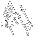
- the control frame 5 comprises a pair of substantially straight, elongated members 6 which are disposed beneath the widthwise (or lateral) centers of the driver's seat and the passenger seat, respectively, and extend in the fore-and-aft direction of the vehicle body.
- a front portion of each of the pair of elongated members 6 is adapted to be deformable so as to absorb an impact energy resulting from a vehicle crash and at the same time produce a temporal rearward movement of the control frame 5 relative to the main frame 4 upon occurrence of a vehicle crash.
- the pair of elongated members 6 are connected to each other by cross bars 20 to form the ladder-like control frame 5.
- control frame 5 a substantial part of the control frame 5 is constituted by the pair of elongated members 6 without a floor panel whereby the weight of the control frame 5 is significantly reduced.
- a stay 7 On a rear portion of each elongated member 6 is fixedly provided a stay 7 to which a seat 9 is connected (described in more detail later), with both ends of a seat belt 8 for restraining a vehicle occupant P is connected to the seat 9.
- the front ends of the left and right side frames 1 of the main frame 4 and those of the elongated members 6 of the control frame 5 are joined by a front member 10 extending in a lateral direction of the vehicle body.
- the front portions of the left and right side frames 1 of the main frame 4 as well as the front portions of the elongated members 6 of the control frame 5 undergo a compressive deformation under the crash load at the time of a vehicle crash, and thereby perform the function of reducing the deceleration acting on the passenger compartment of the vehicle and absorbing the impact energy before the deformation of the passenger compartment begins.
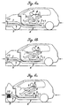
- the front portions of the elongated members 6 of the control frame 5 is adapted to be less deformable than those of the side frames 1 of the main frame 4 at the time of a vehicle crash so as to optimize the deceleration pattern of the control frame 5 and hence the seat 9, as described in detail with reference to Figures 4a-4c later.
- Part of the main frame 4 opposing the rear ends of the elongated members 6 of the control frame 5 is provided with a stopper 11 for limiting the rearward movement of the control frame 5 and acting as a force generating means for applying a forward force to the control frame 5.
- a front surface of the stopper 11 opposing the rear ends of the elongated members 6 is provided with a damper member D for appropriately adjusting the negative deceleration (acceleration) applied on the control frame 5.
- each seat 9 (the driver's seat and passenger seat) is moveable in the fore-and aft direction on the front floor 3 within a range defined by the guide rails 12.
- the stays 7 secured to the elongated members 6 are passed into the vehicle compartment through openings 14 formed in the front floor 3.
- a rack member 16 On top of each stay 7 is attached a rack member 16 that is engaged with a latch finger 15 pivotably connected to the seat 9 for securing the seat at an adjusted position.
- the seat position adjustment mechanism may not be limited to the combination of the latch finger 15 and the rack member 16, and any other seat position adjustment mechanism known in public may be adopted.
- each of the pair of longitudinally extending elongated members 6 passes just below the widthwise center or the center of gravity of the corresponding seat 9 and the seat position adjustment mechanism (latch finger 15, rack member 16) is provided between the seat 9 and the corresponding elongated member 6 of the control frame 5 so that the position of each seat 9 is made adjustable with respect to the control frame 5.
- the seat position adjustment mechanism latch finger 15, rack member 16
- the seat position adjustment mechanism provided between the seat 9 and the elongated member 6 of the control frame 5 allows adjustment of the position of the seat 9 at usual times and in case of a crash, functions to connect the control frame 5 and the seat 9 integrally so that precise control of the seat deceleration can be achieved. Since the control frame 5 does not need to be equipped with a floor panel and a pair of seat slide guide rails for the purpose of seat position adjustment, the weight of the control frame 5 is significantly reduced.
- control frame 5 may be preferably used as a sub-frame for a front wheel suspension system.
- the deformation of the vehicle body starts from the deformation of the front portions of the side frames 1 of the main frame 4 and the elongated members 6 of the control frame 5. Because the mass of the control frame 5 is substantially small as compared with the deformation stress that is produced in the front portion of the control frame 5, the seat 9 connected to the control frame 5 starts decelerating earlier at a deceleration level which builds up more rapidly and sharply than the main frame 4 (interval "a" of Figure 5). Thus, the seat 9 apparently moves rearward relative to the front floor 3 of the main frame 4 which continues to move forward due to the compressive deformation of the side frames 1 ( Figure 4a).
- the control frame 5 carrying the seat 9 comprises an elongated member 6 extending in the fore-and-aft direction of the vehicle body and having a portion adapted to be deformable at the time of a vehicle crash so that the mass of the control frame 5 is minimized.
- the minimized mass of the control frame 5 can in turn reduce the weight of the force generating means (stopper 11) for applying an acceleration to the seat 9 which is substantially integral with the control frame 5.
- the present invention is quite effective in decreasing the weight of the vehicle body and reducing the manufacturing cost of the same.
- control frame 5 need not have a floor panel and a pair of seat slide guide rails for seat position adjustment, allowing further reduction in the weight of the control frame 5.
- the seat carrying member comprises an elongated member extending in a fore-and-aft direction of the vehicle body and having a portion adapted to be deformable at the time of a vehicle crash.
- the seat is preferably connected to the elongated member of the seat carrying member at a widthwise center of the seat so that at the time of a vehicle crash, the inertial force of the seat and the vehicle occupant will act in the direction that the elongated member extends and substantially no horizontal moment will be applied on the seat carrying member.
- a seat position adjustment mechanism is preferably provided between the seat and the elongated member of the seat carrying member.
Landscapes
- Engineering & Computer Science (AREA)
- Transportation (AREA)
- Mechanical Engineering (AREA)
- Aviation & Aerospace Engineering (AREA)
- Chemical & Material Sciences (AREA)
- Combustion & Propulsion (AREA)
- Seats For Vehicles (AREA)
- Body Structure For Vehicles (AREA)
Applications Claiming Priority (4)
| Application Number | Priority Date | Filing Date | Title |
|---|---|---|---|
| JP20891099 | 1999-07-23 | ||
| JP20891099A JP4048004B2 (ja) | 1999-07-23 | 1999-07-23 | 自動車の車体構造 |
| JP20886599 | 1999-07-23 | ||
| JP11208865A JP2001030947A (ja) | 1999-07-23 | 1999-07-23 | 自動車の車体構造 |
Publications (2)
| Publication Number | Publication Date |
|---|---|
| EP1070657A1 true EP1070657A1 (fr) | 2001-01-24 |
| EP1070657B1 EP1070657B1 (fr) | 2003-08-13 |
Family
ID=26517089
Family Applications (1)
| Application Number | Title | Priority Date | Filing Date |
|---|---|---|---|
| EP00115671A Expired - Lifetime EP1070657B1 (fr) | 1999-07-23 | 2000-07-20 | Structure de chassis de véhicule automobile |
Country Status (3)
| Country | Link |
|---|---|
| US (1) | US6312038B1 (fr) |
| EP (1) | EP1070657B1 (fr) |
| DE (1) | DE60004447T2 (fr) |
Cited By (3)
| Publication number | Priority date | Publication date | Assignee | Title |
|---|---|---|---|---|
| EP1266804A3 (fr) * | 2001-06-12 | 2003-09-03 | Honda Giken Kogyo Kabushiki Kaisha | Système de protection des passagers d'un véhicule en cas de choc latéral |
| WO2003104055A1 (fr) * | 2002-01-20 | 2003-12-18 | Neelam Agarwal | Systeme composite de securite de passager et de protection de vehicule |
| DE10243354B4 (de) * | 2001-09-18 | 2005-11-24 | Honda Giken Kogyo K.K. | Kraftfahrzeug-Insassenschutzsystem |
Families Citing this family (15)
| Publication number | Priority date | Publication date | Assignee | Title |
|---|---|---|---|---|
| SE514294C2 (sv) * | 1998-09-30 | 2001-02-05 | Volvo Lastvagnar Ab | Anordning som möjliggör förskjutning av förarutrymmet hos ett fordon |
| WO2000031344A1 (fr) * | 1998-11-26 | 2000-06-02 | Lotus Cars Limited | Absorbeur d'energie prevu pour absorber l'energie lors d'un choc avec un objet mobile |
| JP2001163137A (ja) * | 1999-12-06 | 2001-06-19 | Honda Motor Co Ltd | 乗員保護装置 |
| JP3904384B2 (ja) * | 2000-10-31 | 2007-04-11 | 本田技研工業株式会社 | 乗員保護装置 |
| JP3725043B2 (ja) * | 2001-04-25 | 2005-12-07 | 株式会社日立製作所 | 軌条車両 |
| JP4006495B2 (ja) * | 2001-08-01 | 2007-11-14 | 日野自動車株式会社 | 車両用シート構造 |
| JP2004188998A (ja) * | 2002-12-06 | 2004-07-08 | Honda Motor Co Ltd | 車体フレーム |
| US6715593B1 (en) * | 2002-09-27 | 2004-04-06 | Ford Global Technologies, Llc | Crush tube assembly |
| DE102004029745B4 (de) * | 2004-06-19 | 2016-10-20 | Volkswagen Ag | Pralldämpfungsvorrichtung für ein Fahrzeug |
| US7380830B2 (en) * | 2005-02-03 | 2008-06-03 | Honda Motor Co., Ltd. | Vehicle front body structure |
| US7387327B2 (en) | 2005-06-24 | 2008-06-17 | University Of Washington | Structure and system for occupant protection in a side impact automobile collision and methods of use thereof |
| US7611197B2 (en) * | 2006-06-26 | 2009-11-03 | International Truck Intellectual Property Company, Llc | Occupant restraint passenger seat assembly with load-sensing energy absorption feature |
| DE102009034911A1 (de) * | 2009-07-28 | 2011-02-03 | GM Global Technology Operations, Inc., Detroit | Karosserie für ein Kraftfahrzeug |
| US8292357B2 (en) | 2009-12-03 | 2012-10-23 | Ford Global Technologies | Reinforced closed section assembly |
| US9365241B1 (en) * | 2015-03-04 | 2016-06-14 | Honda Motor Co., Ltd. | Vehicle crash management apparatus and methods of use and manufacture thereof |
Citations (9)
| Publication number | Priority date | Publication date | Assignee | Title |
|---|---|---|---|---|
| US3992046A (en) * | 1973-09-05 | 1976-11-16 | Dr. -Ing. H.C.F. Porsche Aktiengesellschaft | Safety installation for motor vehicles |
| DE4323543C1 (de) * | 1993-03-31 | 1994-10-06 | Mueller Franz Dipl Ing Fh | Sicherheitseinrichtung für Fahrzeuge |
| JPH07101354A (ja) | 1993-10-05 | 1995-04-18 | Isuzu Motors Ltd | 車両用サイドメンバ |
| US5409262A (en) * | 1993-08-31 | 1995-04-25 | Mclennan; Ronald A. | Vehicle safety system |
| US5626203A (en) * | 1995-11-01 | 1997-05-06 | Habib; Mostafa S. | Active control of a vehicle occupant's body in frontal collision |
| US5636424A (en) * | 1991-07-19 | 1997-06-10 | Massachusetts Institute Of Technology | Safety seat |
| DE19938940A1 (de) * | 1998-08-20 | 2000-03-02 | Honda Motor Co Ltd | Fahrzeuginsassen-Schutzsystem |
| US9377366B2 (en) | 2013-07-08 | 2016-06-28 | Pixart Imaging Inc. | Navigation device including thermal sensor |
| US9376888B2 (en) | 2013-08-08 | 2016-06-28 | Halliburton Energy Services, Inc. | Diverting resin for stabilizing particulate in a well |
Family Cites Families (4)
| Publication number | Priority date | Publication date | Assignee | Title |
|---|---|---|---|---|
| US3001815A (en) * | 1958-02-25 | 1961-09-26 | Robert C Weber | Bumper actuated vehicle safety seat |
| DE3424928A1 (de) * | 1984-07-06 | 1986-01-16 | Walter 8720 Schweinfurt Lindwurm | Schleudersitz - sicherheitsanlage fuer kraftfahrzeuge |
| US5947543A (en) * | 1997-04-03 | 1999-09-07 | Hubbard; Leo James | Vehicle safety system |
| US6092853A (en) * | 1997-04-03 | 2000-07-25 | Hubbard; Leo James | Vehicle safety system |
-
2000
- 2000-07-20 DE DE60004447T patent/DE60004447T2/de not_active Expired - Fee Related
- 2000-07-20 EP EP00115671A patent/EP1070657B1/fr not_active Expired - Lifetime
- 2000-07-21 US US09/621,336 patent/US6312038B1/en not_active Expired - Fee Related
Patent Citations (9)
| Publication number | Priority date | Publication date | Assignee | Title |
|---|---|---|---|---|
| US3992046A (en) * | 1973-09-05 | 1976-11-16 | Dr. -Ing. H.C.F. Porsche Aktiengesellschaft | Safety installation for motor vehicles |
| US5636424A (en) * | 1991-07-19 | 1997-06-10 | Massachusetts Institute Of Technology | Safety seat |
| DE4323543C1 (de) * | 1993-03-31 | 1994-10-06 | Mueller Franz Dipl Ing Fh | Sicherheitseinrichtung für Fahrzeuge |
| US5409262A (en) * | 1993-08-31 | 1995-04-25 | Mclennan; Ronald A. | Vehicle safety system |
| JPH07101354A (ja) | 1993-10-05 | 1995-04-18 | Isuzu Motors Ltd | 車両用サイドメンバ |
| US5626203A (en) * | 1995-11-01 | 1997-05-06 | Habib; Mostafa S. | Active control of a vehicle occupant's body in frontal collision |
| DE19938940A1 (de) * | 1998-08-20 | 2000-03-02 | Honda Motor Co Ltd | Fahrzeuginsassen-Schutzsystem |
| US9377366B2 (en) | 2013-07-08 | 2016-06-28 | Pixart Imaging Inc. | Navigation device including thermal sensor |
| US9376888B2 (en) | 2013-08-08 | 2016-06-28 | Halliburton Energy Services, Inc. | Diverting resin for stabilizing particulate in a well |
Cited By (3)
| Publication number | Priority date | Publication date | Assignee | Title |
|---|---|---|---|---|
| EP1266804A3 (fr) * | 2001-06-12 | 2003-09-03 | Honda Giken Kogyo Kabushiki Kaisha | Système de protection des passagers d'un véhicule en cas de choc latéral |
| DE10243354B4 (de) * | 2001-09-18 | 2005-11-24 | Honda Giken Kogyo K.K. | Kraftfahrzeug-Insassenschutzsystem |
| WO2003104055A1 (fr) * | 2002-01-20 | 2003-12-18 | Neelam Agarwal | Systeme composite de securite de passager et de protection de vehicule |
Also Published As
| Publication number | Publication date |
|---|---|
| US6312038B1 (en) | 2001-11-06 |
| DE60004447T2 (de) | 2004-03-25 |
| EP1070657B1 (fr) | 2003-08-13 |
| DE60004447D1 (de) | 2003-09-18 |
Similar Documents
| Publication | Publication Date | Title |
|---|---|---|
| US6312038B1 (en) | Automotive vehicle body structure | |
| US6186574B1 (en) | Vehicle occupant protection system | |
| EP1106479B1 (fr) | Structure de carrosserie automobile pour sécurité de collision amélioré | |
| EP1266804B1 (fr) | Système de protection des passagers d'un véhicule en cas de choc latéral | |
| US8240736B2 (en) | Deceleration responsive vehicle seat | |
| US6027167A (en) | Method to safely restrain occupants in a crashing vehicle and a seat constructed to perform said method | |
| JP2001163136A (ja) | 乗員保護装置 | |
| EP1067014A1 (fr) | Système de protection des passagers d'un véhicule | |
| EP1078812B1 (fr) | Système de protection des occupants d'un véhicule | |
| JP2001163137A (ja) | 乗員保護装置 | |
| JP2002046513A (ja) | 自動車用シート | |
| KR20200091753A (ko) | 자동차용 시트의 충격 방어 장치 | |
| JP4048004B2 (ja) | 自動車の車体構造 | |
| JP3016454B2 (ja) | 車両のパワーユニットマウント構造 | |
| WO2008116112A1 (fr) | Ensemble rail de siège à broches de charge | |
| JP2000016209A (ja) | 衝突エネルギー吸収車体 | |
| JPH05240283A (ja) | 車両のパワーユニット支持構造 | |
| WO2024102103A1 (fr) | Plateforme d'amortissement des chocs pour sièges de véhicule | |
| JP2001030947A (ja) | 自動車の車体構造 | |
| KR100483267B1 (ko) | 서브마린 방지 시트 | |
| JP2001163175A (ja) | 乗員保護装置 | |
| KR20030092950A (ko) | 서브마린 방지 시트 | |
| JP2001225764A (ja) | 自動車の車体構造 | |
| JPH0761273A (ja) | 車両用シート | |
| KR20030097224A (ko) | 목 부상 방지를 위한 자동차 시트 고정구조 |
Legal Events
| Date | Code | Title | Description |
|---|---|---|---|
| PUAI | Public reference made under article 153(3) epc to a published international application that has entered the european phase |
Free format text: ORIGINAL CODE: 0009012 |
|
| AK | Designated contracting states |
Kind code of ref document: A1 Designated state(s): DE FR GB |
|
| AX | Request for extension of the european patent |
Free format text: AL;LT;LV;MK;RO;SI |
|
| 17P | Request for examination filed |
Effective date: 20010205 |
|
| AKX | Designation fees paid |
Free format text: DE FR GB |
|
| 17Q | First examination report despatched |
Effective date: 20020828 |
|
| GRAH | Despatch of communication of intention to grant a patent |
Free format text: ORIGINAL CODE: EPIDOS IGRA |
|
| GRAH | Despatch of communication of intention to grant a patent |
Free format text: ORIGINAL CODE: EPIDOS IGRA |
|
| GRAA | (expected) grant |
Free format text: ORIGINAL CODE: 0009210 |
|
| AK | Designated contracting states |
Designated state(s): DE FR GB |
|
| REG | Reference to a national code |
Ref country code: GB Ref legal event code: FG4D |
|
| REF | Corresponds to: |
Ref document number: 60004447 Country of ref document: DE Date of ref document: 20030918 Kind code of ref document: P |
|
| ET | Fr: translation filed | ||
| PLBE | No opposition filed within time limit |
Free format text: ORIGINAL CODE: 0009261 |
|
| STAA | Information on the status of an ep patent application or granted ep patent |
Free format text: STATUS: NO OPPOSITION FILED WITHIN TIME LIMIT |
|
| PGFP | Annual fee paid to national office [announced via postgrant information from national office to epo] |
Ref country code: DE Payment date: 20040630 Year of fee payment: 5 |
|
| PGFP | Annual fee paid to national office [announced via postgrant information from national office to epo] |
Ref country code: GB Payment date: 20040715 Year of fee payment: 5 |
|
| PGFP | Annual fee paid to national office [announced via postgrant information from national office to epo] |
Ref country code: FR Payment date: 20040727 Year of fee payment: 5 |
|
| 26N | No opposition filed |
Effective date: 20040514 |
|
| PG25 | Lapsed in a contracting state [announced via postgrant information from national office to epo] |
Ref country code: GB Free format text: LAPSE BECAUSE OF NON-PAYMENT OF DUE FEES Effective date: 20050720 |
|
| PG25 | Lapsed in a contracting state [announced via postgrant information from national office to epo] |
Ref country code: DE Free format text: LAPSE BECAUSE OF NON-PAYMENT OF DUE FEES Effective date: 20060201 |
|
| GBPC | Gb: european patent ceased through non-payment of renewal fee |
Effective date: 20050720 |
|
| PG25 | Lapsed in a contracting state [announced via postgrant information from national office to epo] |
Ref country code: FR Free format text: LAPSE BECAUSE OF NON-PAYMENT OF DUE FEES Effective date: 20060331 |
|
| REG | Reference to a national code |
Ref country code: FR Ref legal event code: ST Effective date: 20060331 |