EP1070865A2 - Palier à roulement linéaire pour la transmission de couples - Google Patents
Palier à roulement linéaire pour la transmission de couples Download PDFInfo
- Publication number
- EP1070865A2 EP1070865A2 EP00113212A EP00113212A EP1070865A2 EP 1070865 A2 EP1070865 A2 EP 1070865A2 EP 00113212 A EP00113212 A EP 00113212A EP 00113212 A EP00113212 A EP 00113212A EP 1070865 A2 EP1070865 A2 EP 1070865A2
- Authority
- EP
- European Patent Office
- Prior art keywords
- section
- roller bearing
- profile element
- linear roller
- wall sections
- Prior art date
- Legal status (The legal status is an assumption and is not a legal conclusion. Google has not performed a legal analysis and makes no representation as to the accuracy of the status listed.)
- Ceased
Links
- 238000005096 rolling process Methods 0.000 title claims abstract description 73
- 230000005540 biological transmission Effects 0.000 title 1
- 230000004087 circulation Effects 0.000 claims description 22
- 230000036316 preload Effects 0.000 description 10
- 238000004519 manufacturing process Methods 0.000 description 8
- 239000002184 metal Substances 0.000 description 3
- 229910000639 Spring steel Inorganic materials 0.000 description 2
- 230000008901 benefit Effects 0.000 description 2
- 238000006073 displacement reaction Methods 0.000 description 2
- 238000004080 punching Methods 0.000 description 2
- 238000003860 storage Methods 0.000 description 2
- 241000143252 Idaea infirmaria Species 0.000 description 1
- 230000009471 action Effects 0.000 description 1
- 238000005452 bending Methods 0.000 description 1
- 230000008859 change Effects 0.000 description 1
- 230000006835 compression Effects 0.000 description 1
- 238000007906 compression Methods 0.000 description 1
- 238000009826 distribution Methods 0.000 description 1
- 230000000694 effects Effects 0.000 description 1
- 230000000763 evoking effect Effects 0.000 description 1
- 238000009434 installation Methods 0.000 description 1
- 239000000463 material Substances 0.000 description 1
- 238000011089 mechanical engineering Methods 0.000 description 1
- 238000000034 method Methods 0.000 description 1
- 230000008569 process Effects 0.000 description 1
- 230000009467 reduction Effects 0.000 description 1
Images


Classifications
-
- F—MECHANICAL ENGINEERING; LIGHTING; HEATING; WEAPONS; BLASTING
- F16—ENGINEERING ELEMENTS AND UNITS; GENERAL MEASURES FOR PRODUCING AND MAINTAINING EFFECTIVE FUNCTIONING OF MACHINES OR INSTALLATIONS; THERMAL INSULATION IN GENERAL
- F16C—SHAFTS; FLEXIBLE SHAFTS; ELEMENTS OR CRANKSHAFT MECHANISMS; ROTARY BODIES OTHER THAN GEARING ELEMENTS; BEARINGS
- F16C27/00—Elastic or yielding bearings or bearing supports, for exclusively rotary movement
- F16C27/04—Ball or roller bearings, e.g. with resilient rolling bodies
-
- F—MECHANICAL ENGINEERING; LIGHTING; HEATING; WEAPONS; BLASTING
- F16—ENGINEERING ELEMENTS AND UNITS; GENERAL MEASURES FOR PRODUCING AND MAINTAINING EFFECTIVE FUNCTIONING OF MACHINES OR INSTALLATIONS; THERMAL INSULATION IN GENERAL
- F16C—SHAFTS; FLEXIBLE SHAFTS; ELEMENTS OR CRANKSHAFT MECHANISMS; ROTARY BODIES OTHER THAN GEARING ELEMENTS; BEARINGS
- F16C29/00—Bearings for parts moving only linearly
- F16C29/04—Ball or roller bearings
- F16C29/06—Ball or roller bearings in which the rolling bodies circulate partly without carrying load
- F16C29/068—Ball or roller bearings in which the rolling bodies circulate partly without carrying load with the bearing body fully encircling the guide rail or track
- F16C29/0692—Ball or roller bearings in which the rolling bodies circulate partly without carrying load with the bearing body fully encircling the guide rail or track the bearing body encircles a guide rail or track of non-circular cross-section, e.g. with grooves or protrusions, i.e. the linear bearing is suited to transmit torque
- F16C29/0695—Ball or roller bearings in which the rolling bodies circulate partly without carrying load with the bearing body fully encircling the guide rail or track the bearing body encircles a guide rail or track of non-circular cross-section, e.g. with grooves or protrusions, i.e. the linear bearing is suited to transmit torque with balls
- F16C29/0697—Ball or roller bearings in which the rolling bodies circulate partly without carrying load with the bearing body fully encircling the guide rail or track the bearing body encircles a guide rail or track of non-circular cross-section, e.g. with grooves or protrusions, i.e. the linear bearing is suited to transmit torque with balls with polygonal guide rail or track
-
- F—MECHANICAL ENGINEERING; LIGHTING; HEATING; WEAPONS; BLASTING
- F16—ENGINEERING ELEMENTS AND UNITS; GENERAL MEASURES FOR PRODUCING AND MAINTAINING EFFECTIVE FUNCTIONING OF MACHINES OR INSTALLATIONS; THERMAL INSULATION IN GENERAL
- F16C—SHAFTS; FLEXIBLE SHAFTS; ELEMENTS OR CRANKSHAFT MECHANISMS; ROTARY BODIES OTHER THAN GEARING ELEMENTS; BEARINGS
- F16C29/00—Bearings for parts moving only linearly
- F16C29/002—Elastic or yielding linear bearings or bearing supports
-
- F—MECHANICAL ENGINEERING; LIGHTING; HEATING; WEAPONS; BLASTING
- F16—ENGINEERING ELEMENTS AND UNITS; GENERAL MEASURES FOR PRODUCING AND MAINTAINING EFFECTIVE FUNCTIONING OF MACHINES OR INSTALLATIONS; THERMAL INSULATION IN GENERAL
- F16C—SHAFTS; FLEXIBLE SHAFTS; ELEMENTS OR CRANKSHAFT MECHANISMS; ROTARY BODIES OTHER THAN GEARING ELEMENTS; BEARINGS
- F16C29/00—Bearings for parts moving only linearly
- F16C29/12—Arrangements for adjusting play
- F16C29/123—Arrangements for adjusting play using elastic means
-
- F—MECHANICAL ENGINEERING; LIGHTING; HEATING; WEAPONS; BLASTING
- F16—ENGINEERING ELEMENTS AND UNITS; GENERAL MEASURES FOR PRODUCING AND MAINTAINING EFFECTIVE FUNCTIONING OF MACHINES OR INSTALLATIONS; THERMAL INSULATION IN GENERAL
- F16C—SHAFTS; FLEXIBLE SHAFTS; ELEMENTS OR CRANKSHAFT MECHANISMS; ROTARY BODIES OTHER THAN GEARING ELEMENTS; BEARINGS
- F16C3/00—Shafts; Axles; Cranks; Eccentrics
- F16C3/02—Shafts; Axles
- F16C3/03—Shafts; Axles telescopic
- F16C3/035—Shafts; Axles telescopic with built-in bearings
-
- F—MECHANICAL ENGINEERING; LIGHTING; HEATING; WEAPONS; BLASTING
- F16—ENGINEERING ELEMENTS AND UNITS; GENERAL MEASURES FOR PRODUCING AND MAINTAINING EFFECTIVE FUNCTIONING OF MACHINES OR INSTALLATIONS; THERMAL INSULATION IN GENERAL
- F16C—SHAFTS; FLEXIBLE SHAFTS; ELEMENTS OR CRANKSHAFT MECHANISMS; ROTARY BODIES OTHER THAN GEARING ELEMENTS; BEARINGS
- F16C2326/00—Articles relating to transporting
- F16C2326/20—Land vehicles
- F16C2326/24—Steering systems, e.g. steering rods or columns
Definitions
- Linear roller bearings are used in almost all areas of mechanical engineering and used in automotive engineering. With such bearings become one another longitudinally displaceable components mounted against each other. In Applications with telescopically variable shafts must be such bearing additionally the torques guided by the shaft transfer. Telescopically variable waves are z. B. as Steering shafts used by steering columns of modern motor vehicles. At such steering columns is the position of the steering wheel in the vehicle interior adaptable to the individual size and posture of the operator. This changes the absolute distance between the steering wheel and the steering gear. This change in distance is telescopically displaceable into one another arranged shaft ends can be corrected.
- the Steering shafts can also be coupled in a torsion-proof manner.
- the position of the Steering wheel is either manually operated by the operator or adjusted via electric motors. With both adjustment options, the in Sliding seat of the telescopically displaceable shafts occurring forces should not be too high.
- the displacement forces small and in a relatively constant size over the entire displacement range held.
- steering shafts are also during vehicle operation Subject to changes in length. These changes in length are short-stroke and oscillating and with a real movement of the steering gear the lower steering shaft end to the relatively fixed upper steering shaft end evoked.
- linear roller bearings are different.
- linear roller bearings are often used for cost reasons used that only a limited stroke of one component compared to allow another component.
- These bearings usually point between the rolling elements which are longitudinally displaceable relative to one another in a cage on.
- the cage tends to oscillate during operation short-stroke movements for hiking.
- the rolling elements do not roll off but slide. In this way, the cage reaches a position from the Functional stroke of the cage is no longer guaranteed. Subsequently are for larger stroke movements but also for short stroke movements the rolling elements and the cage are subjected to forced movements for sliding and lead to impermissible wear.
- the spring elements clamp in Rolling elements against the outer component.
- the play-free seat of the components to each other is guaranteed.
- Adjustment movements of the components in Longitudinal direction to each other through the rolling movement of the rolling elements smooth and low wear.
- the components are low Gap dimension, d. H. with a dimension that is ⁇ the spring travel of the spring elements, arranged to each other.
- the spring elements are designed so that the Rollers absorb any torque in the case of normal turning forces. But if one becomes against the other component under the effect of one twisted high torque, the spring elements deflect until the Components lie next to each other. The torque is now directly over the Transfer the wall of the components and the rolling elements are relieved.
- the Spring elements must be adapted to the normal turning forces. she thus work in normal operation with a relatively high preload. Under this high preload suffers the smooth running with which a linear bearing may have to work.
- the object of the invention is therefore to provide a linear roller bearing which Disadvantages of the aforementioned designs of linear roller bearings avoided.
- a linear roller bearing with ball revolutions is created at which the rolling element circulation is arranged in a cage and the cage between an inner wall section of an outer profile and a outer wall section of an inner profile element is arranged, and that one of the profile elements at least one in the rolling element circulation existing and loaded rolling element acting preloading for has play-free prestressing of the profile elements against one another.
- a linear roller bearing is simple and inexpensive to manufacture. Either the inner profile element as well as the outer profile element are easy to design and do not need with additional rolling element raceways, Cage brackets or other necessary for the rolling elements Elements.
- the rolling element circulation is in the rolling element cage educated.
- the guideways of the rolling elements lead to one revolution are connected to each other only in the cage.
- the required clearance for the return of the unloaded rolling elements is included simple means, e.g. B. through a groove with relatively large tolerances, with to introduce little effort into one or both of the profile elements.
- the Advantages of a linear roller bearing with rolling element circulation are used without however, accept the disadvantages mentioned at the beginning.
- Such a bearing is easy to design without play. It is free of play performed by the rolling elements located in the load zone with a Biasing means loaded against a wall section of one or both Profile elements are supported while the biasing means itself on one or both of the profile elements is arranged. It is conceivable, for. B. use of spring plates designed as a career. The spring plates are simple by punching and bending or stamping from spring steel or spring steel Similar hardened material made and z. B. one in her Cross section of arched profile. The spring plate is seen in cross section arched by a dimension that is at least minimally larger than the largest possible theoretical play should be due to manufacturing tolerances in storage.
- the spring plate produces preloaded in the assembled state in the Linear roller bearing a preload on the loads running on it Rolling elements.
- the loaded rolling elements are against the opposite one Prestressed wall section.
- Such spring plates can also be in both opposite or mutually assigned wall sections inserted his.
- the sheet thickness of the spring sheets and / or the execution of the curvature depends on the required preload.
- the preload must not be so great about the spring plate and the rolling element torques to transfer to the other wall section. It is enough if this Spring plates generate so much preload that the linear bearing for Longitudinal movements and in the operating state is designed without play.
- an embodiment of the invention provides that the biasing means at least one resilient and resilient trained career section on at least one of the other associated wall sections is formed.
- arched spring plate mentioned at the beginning.
- Spring plate is Spring plate, however, only seen in cross section in the section arched in where the load zone is.
- the spring action is the same as that in the the previous section.
- an im essential flat sheet metal can be used, which is located on one of the Supported wall sections and the pretension by means of a leverage generates the loaded rolling elements.
- Such spring plates are minimal Manufacturing effort.
- the spring preload is due to the sheet thickness and the Lever length can be influenced.
- the load zone is provided when the torques initiate so far that the each other assigned wall sections move towards each other until at least a portion of the cage's torques from one of the other assigned wall sections to the other of the mutually assigned Transfers wall sections.
- the cage thus forms, apart from a means for Guide the rolling elements also a means for transmitting the torques.
- the cage is arranged at a relatively short distance from each of the walls. The size of the. Is determined by the distance of the cage to the walls Torque determines which is first transmitted from the rolling elements only. If this torque is exceeded, the load zone and the Walls move towards each other until they reach the cage or the one Pinch the section of the cage between them.
- the size of the Torque that is still transmitted via the rolling elements and raceways is due to the design of the spring elements in the load zone and As already mentioned, it can be determined by the distance between the cage and the wall. In a further embodiment, it is therefore provided in the load zone trained track section to make resilient.
- A can such track section either on a wall section, alternatively on inner profile element or on the outer profile element, or on each other assigned wall sections. It is in this Design further provided that the resiliently trained Compress track sections as far as the torque is applied mutually assigned wall sections move against each other again until they clamp the section of the cage between them or alternatively themselves touch each other directly.
- the inner Profile element is formed by an inner ring of the linear roller bearing and that the outer profile element is formed by a sleeve of the linear roller bearing.
- Such elements can also be machined in the chipless process, Manufacture inexpensively, especially in mass production.
- the advantage of Manufacturing individual elements lies in the pipes and shafts in or on to whom such a linear roller bearing is used is relatively simple can be designed.
- the inner ring or the outer ring are in the or preferably pressed onto the simply designed profiles. It is also conceivable that the inner wall sections or the raceways for the drain the rolling elements in the load zone directly through the surface of the telescopic mutually displaceable components is formed.
- the shaft elements and the associated ones Outer tubes have a simple geometry. That's why with one more Embodiment of the invention provided the inner profile in his Cross section polygonal with at least three outer wall sections to train. Three outward-facing wall sections secure one even distribution of those resulting from the introduction of torque Forces on all load zones of the linear bearing. Regardless of that, however also rectangular, cuboid or other polygonal cross-sectional shapes applicable.
- Another embodiment of the The invention therefore provides that one or both of the other assigned wall sections a thin-walled elastic resilient trained career is provided and this career in the field of load-free zone has a longitudinal groove.
- This longitudinal groove preferably through Punching introduced ensures that the rolling elements are relieved in their circulation and run back.
- the career springs at least in the load zone so far that the assigned to each other Band sections move against each other until they touch each other or clamp a section of the cage between them. For compression sufficient space is created in the corresponding profile element.
- the Spring plates are easily inserted, snapped into the profiles, welded or otherwise attached.
- the inner profile element by a section a steering shaft and the outer profile element through the second section a steering shaft of a steering system of a motor vehicle is formed.
- a big part of the components used for steering columns of modern motor vehicles is by Machined sheet metal. Steering columns of this type must be used be easy to manufacture, have a low weight, small installation space make use of it, work reliably and comfortably.
- the linear bearing according to the invention with its embodiments especially for use between telescopically displaceable Steering shafts suitable.
- the linear roller bearing 1 is by an inner profile element 2, an outer profile element 3 and rolling element revolutions 4 are formed.
- the inner Profile element 2 is z. B. on a lower portion of a steering shaft formed and the outer profile element 3 at an upper portion of a Steering shaft.
- the inner profile element 2 is polygonal with three provided the same outer wall sections 2a.
- Everyone outside Wall section 2a is an inner wall section 3a of the outer Profile element 3 assigned.
- Each outer wall section 2a is by means of Rolling elements 5 are mounted on the inner wall section 3a assigned to them. Between each outer wall section 2a and inner wall section 3a a cage 6 is mounted.
- each cage 6 there is one of the rolling element revolutions 4 formed in which the rolling elements 5 rotate.
- a spring-elastic raceway section 8 inserted in the outer Wall section 3a.
- the track section 8 is seen in cross section with a Provide curvature 7 and mounted with preload in the linear roller bearing 1.
- the track section 8 transmits the preload via in a first Guideway 4a of the ball circulation 4 located rolling elements 5 on the outer wall section 2a.
- the rolling elements 5 are in the first Guideway 4a out through a load zone of the ball circulation 4.
- the Ball circulation 4 also has a second guideway 4b in which the Rolling elements 5 are guided through a load-free zone.
- the on three sides of the Linear bearing 1 secures preload acting on the inner profile element 2 the clearance of the linear roller bearing 1 from.
- Torques are from that inner profile element 2 by means of the outer wall section 2a over the inner wall section 3a on the outer profile element 3 and vice versa transfer.
- the Track section 8 is spring loaded in the load zone.
- FIG. 2 shows a further embodiment of the invention.
- On Linear roller bearing 9 is an inner profile element 10, an outer Profile element 11 and the inner profile element 10 in cross section seen encompassing cage 12 formed.
- the inner profile element 10 is again provided with three outer wall sections 10a.
- Everyone outside Wall section 10a is assigned to two rolling element circulations 13.
- the Rolling elements 14 are in turn formed as balls.
- the rolling elements 14 in a first guideway 13a of the rolling element circulation 13 are of two Sides by a resiliently designed raceway section 15a a pretensioning element designed as a spring plate 15.
- inner wall section 11a assigned to 10a is one of the spring plates 15 inserted.
- a second guideway 13b of the rolling element circulation 13 the relieved rolling elements 14 run back during a linear movement. Torques are generated by the inner profile element 10 over three sections 12a of the cage 12 transferred to the outer profile element 11 by the inner Profile element 10 acts against the sections 12 a of the cage and the cage 12 presses against the inner wall sections 11a of the outer profile element and vice versa.
- the raceway sections 15a spring to the same or unequal parts.
- FIG. 3 shows at 16 another embodiment of a linear roller bearing according to the invention.
- the inner profile element of the linear roller bearing 16 is through formed an inner ring 17.
- a cage 18 surrounds the inner ring 17.
- the cage 18 is between the inner ring 17 and an outer ring 19 outer profile element arranged.
- the inner ring 17 sits on one Shaft section 20.
- the outer ring 19 is in a not fully shown Pressed in housing 21.
- the inner ring 17 has three identically designed outer wall sections 17a.
- In the outer ring 19 are as a biasing means Spring plates 23 inserted.
- the spring plate 23 is on a projection 19a Outer ring 19 added.
- the cage 18 has per outer wall section 17a two rolling element circulations 24.
- Ball circumference 24 passes loaded rolling elements 22 through a load zone.
- This The load zone is defined by a resiliently biased track section 23b of the Spring plate 23 generated.
- the run in the second guideway 24b Rolling body 22 relieves pressure.
- the rolling elements in the second guideway 24b are load-free because they have a longitudinal groove 23a in the spring plate 23 necessary space is created. Torques from the shaft section 20 are over the inner ring 17 and cage sections 18a and the inner Wall sections 19b of the outer ring 19 transferred to the housing 21.
- the Spring plate 23 springs in the area of the load zone.
- Figure 4 shows a section through the linear roller bearing 16 of Figure 3, wherein the cage 18 is shown in plan view. In this view they are adjacent ball revolutions 24 visible in plan view.
- the Rolling elements 22 shown in dashed lines pass through the load zone in the first Guideway 24a. After passing through the first guideway 24a the rolling elements 22 are deflected into the second guideway 24b.
- the Longitudinal groove 23a ensures that the rolling elements 22 load-free the second Pass through guideway 24b.
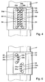
- FIG. 5 and FIG. 6 show alternative arrangements of the ball revolutions 24.
- FIG. 5 shows the ball revolutions 24 in the longitudinal direction of the cage 18 offset but otherwise arranged parallel to each other.
- Figure 6 shows a cage 18 each assigned between each other Wall sections has three ball circulations 24.
Landscapes
- Engineering & Computer Science (AREA)
- General Engineering & Computer Science (AREA)
- Mechanical Engineering (AREA)
- Ocean & Marine Engineering (AREA)
- Bearings For Parts Moving Linearly (AREA)
- Rolling Contact Bearings (AREA)
- Steering Controls (AREA)
Applications Claiming Priority (2)
| Application Number | Priority Date | Filing Date | Title |
|---|---|---|---|
| DE19933875.2A DE19933875B4 (de) | 1999-07-22 | 1999-07-22 | Linearwälzlager zum Übertragen von Drehmomenten |
| DE19933875 | 1999-07-22 |
Publications (2)
| Publication Number | Publication Date |
|---|---|
| EP1070865A2 true EP1070865A2 (fr) | 2001-01-24 |
| EP1070865A3 EP1070865A3 (fr) | 2003-03-26 |
Family
ID=7915343
Family Applications (1)
| Application Number | Title | Priority Date | Filing Date |
|---|---|---|---|
| EP00113212A Ceased EP1070865A3 (fr) | 1999-07-22 | 2000-06-21 | Palier à roulement linéaire pour la transmission de couples |
Country Status (5)
| Country | Link |
|---|---|
| EP (1) | EP1070865A3 (fr) |
| JP (1) | JP2001074047A (fr) |
| KR (1) | KR100714144B1 (fr) |
| BR (1) | BR0003077A (fr) |
| DE (1) | DE19933875B4 (fr) |
Cited By (11)
| Publication number | Priority date | Publication date | Assignee | Title |
|---|---|---|---|---|
| WO2004024535A1 (fr) | 2002-09-13 | 2004-03-25 | Nsk Ltd. | Arbre telescopique de guidage de vehicule |
| WO2004040154A1 (fr) * | 2002-10-31 | 2004-05-13 | Ina-Schaeffler Kg | Palier d'un raccordement telescopique |
| DE10301082A1 (de) * | 2003-01-14 | 2004-07-29 | Timken Gmbh | Wälzlager für Linearbewegungen |
| DE102006058999A1 (de) * | 2006-12-14 | 2008-06-19 | Bayerische Motoren Werke Ag | Drehmomentübertragungseinrichtung |
| DE102007002380B3 (de) * | 2007-01-10 | 2008-06-19 | Thyssenkrupp Presta Ag | Längenveränderbare Lenkspindel |
| US20110193347A1 (en) * | 2008-08-28 | 2011-08-11 | Seabased Ab | A wave-power unit, and a use of a such |
| EP2566742A4 (fr) * | 2010-05-03 | 2016-04-06 | Fuji Autotech Ab | Arbre télescopique |
| US20230114883A1 (en) * | 2021-09-24 | 2023-04-13 | Schaeffler Technologies AG & Co. KG | Intermediate shaft assembly for steering column |
| WO2024051877A1 (fr) * | 2022-09-05 | 2024-03-14 | Schaeffler Technologies AG & Co. KG | Unité de réglage d'une colonne de direction |
| DE102024127844B3 (de) * | 2024-09-25 | 2025-07-03 | Thyssenkrupp Ag | Lenkwelle und Lenksäule für ein Kraftfahrzeug |
| WO2025218843A1 (fr) * | 2024-04-18 | 2025-10-23 | Schaeffler Technologies AG & Co. KG | Unité de réglage d'une colonne de direction |
Families Citing this family (8)
| Publication number | Priority date | Publication date | Assignee | Title |
|---|---|---|---|---|
| DE10324480A1 (de) * | 2003-05-30 | 2004-12-16 | Ina-Schaeffler Kg | Linearwälzlager zum Übertragen von Drehmomenten |
| JP4568179B2 (ja) * | 2005-06-21 | 2010-10-27 | アイセル株式会社 | 直動軸受及びリテーナ |
| DE102006029784A1 (de) * | 2006-06-27 | 2008-01-03 | Ab Skf | Wellenkomponente mit Längsausgleich |
| WO2008117852A1 (fr) * | 2007-03-27 | 2008-10-02 | Thk Co., Ltd. | Unité coulissante à deux étages |
| DE102007015674A1 (de) * | 2007-03-31 | 2008-10-02 | Schaeffler Kg | Wälzlagervorrichtung |
| KR101471198B1 (ko) * | 2008-04-18 | 2014-12-09 | 현대모비스 주식회사 | 고 출력 토크 전달 앗세이를 구비한 전동 조향 장치 |
| CN103934565B (zh) * | 2011-01-19 | 2016-09-14 | 日本轻金属株式会社 | 双层面板的摩擦搅拌接合方法 |
| DE102022132487A1 (de) * | 2022-09-05 | 2024-03-07 | Schaeffler Technologies AG & Co. KG | Verstelleinheit einer Lenksäule |
Citations (2)
| Publication number | Priority date | Publication date | Assignee | Title |
|---|---|---|---|---|
| DE3308831A1 (de) | 1982-11-08 | 1984-05-10 | American Bank Note Co., New York, N.Y. | Verfahren zum herstellen einer erkennbaren lichtbeugenden struktur und danach hergestellter lesbarer aufzeichnungstraeger |
| EP0281723B1 (fr) | 1987-03-12 | 1991-01-02 | FFV Autotech Aktiebolag | Axe téléscopique de transmission de couple avec protection contre surcharge |
Family Cites Families (17)
| Publication number | Priority date | Publication date | Assignee | Title |
|---|---|---|---|---|
| US2341947A (en) * | 1941-05-15 | 1944-02-15 | Roberts David | Chuck |
| US2823960A (en) * | 1955-08-26 | 1958-02-18 | Lempco Products Inc | Die sets for machine presses |
| US3353875A (en) * | 1964-07-27 | 1967-11-21 | Maxwell R Karge | Linear motion bearing assembly |
| CH495514A (de) * | 1968-08-29 | 1970-08-31 | Kummer Freres S A Fabrique De | Verfahren zum Einbau von Laufschienen und Wälzelementen einer Wälzschiebelagerung |
| CH499026A (de) * | 1968-11-04 | 1970-11-15 | Cotti Gianfranco | Kugellager für relative Längsbewegung auf einer Welle |
| DE2164543C3 (de) * | 1971-12-24 | 1978-08-24 | Jean Walterscheid Gmbh, 5204 Lohmar | Teleskopwelle |
| DE2227312C3 (de) * | 1972-06-05 | 1974-12-05 | Georg Mueller Kugellagerfabrik Kg, 8500 Nuernberg | Lager für eine axiale Relativbewegung zweier koaxialer Bauteile |
| SE370772B (fr) * | 1972-09-18 | 1974-10-28 | Skf Ind Trading & Dev | |
| DE3124927A1 (de) * | 1981-06-25 | 1983-03-31 | INA Wälzlager Schaeffler KG, 8522 Herzogenaurach | Wellenkupplung zur drehmomentuebertragung |
| JPS5928773B2 (ja) * | 1982-02-12 | 1984-07-16 | 博 寺町 | 無限摺動用ボ−ルスプライン軸受 |
| JPH0362230U (fr) * | 1989-10-23 | 1991-06-18 | ||
| DE4119819A1 (de) * | 1991-06-15 | 1992-12-17 | Schaeffler Waelzlager Kg | Spielfreie laengsfuehrung einer welle einem aussenteil gegenueber |
| US5201584A (en) * | 1991-09-18 | 1993-04-13 | At&T Bell Laboratories | Mechanism for preloading linear bearing slides |
| JP3222998B2 (ja) * | 1993-07-21 | 2001-10-29 | 日本トムソン株式会社 | ボールスプライン |
| US5722875A (en) * | 1995-05-30 | 1998-03-03 | Tokyo Electron Limited | Method and apparatus for polishing |
| SE9603163L (sv) * | 1996-08-30 | 1997-12-08 | Kolungen Ab | Styrningssystem mellan en slid och en gejder |
| KR100425238B1 (ko) * | 2001-07-14 | 2004-04-06 | 주식회사 에너프리 | 자기 조명 표지판 |
-
1999
- 1999-07-22 DE DE19933875.2A patent/DE19933875B4/de not_active Expired - Fee Related
-
2000
- 2000-06-21 EP EP00113212A patent/EP1070865A3/fr not_active Ceased
- 2000-07-19 JP JP2000219411A patent/JP2001074047A/ja active Pending
- 2000-07-20 KR KR1020000041494A patent/KR100714144B1/ko not_active Expired - Fee Related
- 2000-07-21 BR BR0003077-5A patent/BR0003077A/pt not_active Application Discontinuation
Patent Citations (2)
| Publication number | Priority date | Publication date | Assignee | Title |
|---|---|---|---|---|
| DE3308831A1 (de) | 1982-11-08 | 1984-05-10 | American Bank Note Co., New York, N.Y. | Verfahren zum herstellen einer erkennbaren lichtbeugenden struktur und danach hergestellter lesbarer aufzeichnungstraeger |
| EP0281723B1 (fr) | 1987-03-12 | 1991-01-02 | FFV Autotech Aktiebolag | Axe téléscopique de transmission de couple avec protection contre surcharge |
Cited By (19)
| Publication number | Priority date | Publication date | Assignee | Title |
|---|---|---|---|---|
| WO2004024535A1 (fr) | 2002-09-13 | 2004-03-25 | Nsk Ltd. | Arbre telescopique de guidage de vehicule |
| EP1547903A4 (fr) * | 2002-09-13 | 2006-11-29 | Nsk Ltd | Arbre telescopique de guidage de vehicule |
| WO2004040154A1 (fr) * | 2002-10-31 | 2004-05-13 | Ina-Schaeffler Kg | Palier d'un raccordement telescopique |
| DE10301082A1 (de) * | 2003-01-14 | 2004-07-29 | Timken Gmbh | Wälzlager für Linearbewegungen |
| US6942386B2 (en) | 2003-01-14 | 2005-09-13 | Timken Gmbh | Roller bearing for linear movements |
| DE10301082B4 (de) * | 2003-01-14 | 2007-02-01 | Timken Gmbh | Wälzlager für Linearbewegungen |
| DE102006058999A1 (de) * | 2006-12-14 | 2008-06-19 | Bayerische Motoren Werke Ag | Drehmomentübertragungseinrichtung |
| WO2008083829A1 (fr) | 2007-01-10 | 2008-07-17 | Thyssenkrupp Presta Aktiengesellschaft | Arbre de direction de longueur variable |
| DE102007002380B3 (de) * | 2007-01-10 | 2008-06-19 | Thyssenkrupp Presta Ag | Längenveränderbare Lenkspindel |
| US8435124B2 (en) | 2007-01-10 | 2013-05-07 | Thyssenkrupp Presta Aktiengesellschaft | Variable length steering spindle |
| US20110193347A1 (en) * | 2008-08-28 | 2011-08-11 | Seabased Ab | A wave-power unit, and a use of a such |
| US8471398B2 (en) * | 2008-08-28 | 2013-06-25 | Seabased Ab | Wave power unit, and a use of a such |
| EP2566742A4 (fr) * | 2010-05-03 | 2016-04-06 | Fuji Autotech Ab | Arbre télescopique |
| US20230114883A1 (en) * | 2021-09-24 | 2023-04-13 | Schaeffler Technologies AG & Co. KG | Intermediate shaft assembly for steering column |
| US11858547B2 (en) * | 2021-09-24 | 2024-01-02 | Schaeffler Technologies AG & Co. KG | Intermediate shaft assembly for steering column |
| WO2024051877A1 (fr) * | 2022-09-05 | 2024-03-14 | Schaeffler Technologies AG & Co. KG | Unité de réglage d'une colonne de direction |
| WO2025218843A1 (fr) * | 2024-04-18 | 2025-10-23 | Schaeffler Technologies AG & Co. KG | Unité de réglage d'une colonne de direction |
| WO2025218859A1 (fr) * | 2024-04-18 | 2025-10-23 | Schaeffler Technologies AG & Co. KG | Segment de bille circulante pour une unité de réglage d'une colonne de direction |
| DE102024127844B3 (de) * | 2024-09-25 | 2025-07-03 | Thyssenkrupp Ag | Lenkwelle und Lenksäule für ein Kraftfahrzeug |
Also Published As
| Publication number | Publication date |
|---|---|
| KR100714144B1 (ko) | 2007-05-02 |
| BR0003077A (pt) | 2001-03-13 |
| KR20010015375A (ko) | 2001-02-26 |
| JP2001074047A (ja) | 2001-03-23 |
| DE19933875A1 (de) | 2001-02-01 |
| DE19933875B4 (de) | 2014-10-16 |
| EP1070865A3 (fr) | 2003-03-26 |
Similar Documents
| Publication | Publication Date | Title |
|---|---|---|
| DE19933875B4 (de) | Linearwälzlager zum Übertragen von Drehmomenten | |
| EP2250405B1 (fr) | Engrenage à roue hélicoïdale comportant un palier d'arbre axialement élastique et commande auxiliaire électrique équipée d'un tel engrenage | |
| EP3475146B1 (fr) | Mécanisme de vis-écrou à billes d'une direction assistée électromécanique comportant des corps de déviation pour un retour des billes | |
| WO2014170125A1 (fr) | Double rondelle ondulée comprenant une couche intermédiaire d'amortissement | |
| DE4126317A1 (de) | Lageranordnung mit variabler vorspannung | |
| DE102009036824A1 (de) | Verfahren zum Herstellen einer Gewindemutter eines Kugelgewindetriebes | |
| DE102018116867A1 (de) | Elektromechanischer Aktuator und Hinterachslenkung | |
| DE10301082B4 (de) | Wälzlager für Linearbewegungen | |
| WO2007065592A1 (fr) | Systeme de palier | |
| DE102019105114B4 (de) | Planetengetriebe | |
| WO2013083538A1 (fr) | Vis à billes | |
| EP1375295A1 (fr) | Arbre de direction pour véhicules | |
| EP2530260B1 (fr) | Arbre d'embrayage, actionneur, boîte de vitesses à dispositif de réglage d'arbre à came et régulateur de l'arbre à came | |
| WO1999008920A1 (fr) | Dispositif dote d'un arbre et destine a la transmission de couples | |
| EP0729874A1 (fr) | Clapet de direction | |
| DE102019115232A1 (de) | Elektromechanisch unterstütztes Lenksystem | |
| WO2004036072A1 (fr) | Unite de guidage lineaire | |
| DE102007045671A1 (de) | Wälzlagerung für axial gegeneinander verschiebbare Bauteile, insbesondere für Getriebe-Schaltelemente | |
| EP1128097A2 (fr) | Dispositif pour transmettre des mouvements de selection et/ou de changement de vitesse | |
| DE2750054B2 (de) | Vorrichtung zur Umwandlung einer Drehbewegung in eine Längsbewegung und umgekehrt | |
| EP1226373B1 (fr) | Mecanisme filete comportant une broche et un ecrou | |
| DE10153912A1 (de) | Lagerung in einem Schaltgetriebe | |
| EP2182232A1 (fr) | Roulement à billes linéaire et élément de support de charge correspondant, ainsi que procédé de fabrication et dispositif de formage pour une ébauche d'un élément de support de charge | |
| DE10062680A1 (de) | Lagerung für lineare Bewegungen mit unendlichem Hub und zur Übertragung von Drehmomenten | |
| DE102021200218A1 (de) | Schiebenockenanordnung |
Legal Events
| Date | Code | Title | Description |
|---|---|---|---|
| PUAI | Public reference made under article 153(3) epc to a published international application that has entered the european phase |
Free format text: ORIGINAL CODE: 0009012 |
|
| 17P | Request for examination filed |
Effective date: 20000621 |
|
| AK | Designated contracting states |
Kind code of ref document: A2 Designated state(s): AT BE CH CY DE DK ES FI FR GB GR IE IT LI LU MC NL PT SE |
|
| AX | Request for extension of the european patent |
Free format text: AL;LT;LV;MK;RO;SI |
|
| RAP1 | Party data changed (applicant data changed or rights of an application transferred) |
Owner name: INA-SCHAEFFLER KG |
|
| PUAL | Search report despatched |
Free format text: ORIGINAL CODE: 0009013 |
|
| AK | Designated contracting states |
Kind code of ref document: A3 Designated state(s): AT BE CH CY DE DK ES FI FR GB GR IE IT LI LU MC NL PT SE Designated state(s): AT BE CH CY DE DK ES FI FR GB GR IE IT LI LU MC NL PT SE |
|
| AX | Request for extension of the european patent |
Extension state: AL LT LV MK RO SI |
|
| RIC1 | Information provided on ipc code assigned before grant |
Ipc: 7F 16C 3/035 B Ipc: 7F 16C 29/04 A |
|
| AKX | Designation fees paid |
Designated state(s): CH DE ES FR IT LI SE |
|
| 17Q | First examination report despatched |
Effective date: 20050127 |
|
| RAP1 | Party data changed (applicant data changed or rights of an application transferred) |
Owner name: SCHAEFFLER KG |
|
| 17Q | First examination report despatched |
Effective date: 20050127 |
|
| STAA | Information on the status of an ep patent application or granted ep patent |
Free format text: STATUS: THE APPLICATION HAS BEEN REFUSED |
|
| 18R | Application refused |
Effective date: 20071116 |
|
| P01 | Opt-out of the competence of the unified patent court (upc) registered |
Effective date: 20230522 |