EP1070870A2 - Dispositif de commande d'un embrayage de démarrage dans un véhicule à fonction arrêt moteur en ralenti - Google Patents
Dispositif de commande d'un embrayage de démarrage dans un véhicule à fonction arrêt moteur en ralenti Download PDFInfo
- Publication number
- EP1070870A2 EP1070870A2 EP00114531A EP00114531A EP1070870A2 EP 1070870 A2 EP1070870 A2 EP 1070870A2 EP 00114531 A EP00114531 A EP 00114531A EP 00114531 A EP00114531 A EP 00114531A EP 1070870 A2 EP1070870 A2 EP 1070870A2
- Authority
- EP
- European Patent Office
- Prior art keywords
- hydraulic oil
- engine
- time
- oil pressure
- pressure
- Prior art date
- Legal status (The legal status is an assumption and is not a legal conclusion. Google has not performed a legal analysis and makes no representation as to the accuracy of the status listed.)
- Granted
Links
- 239000010720 hydraulic oil Substances 0.000 claims abstract description 164
- 230000005540 biological transmission Effects 0.000 claims description 33
- 230000007246 mechanism Effects 0.000 claims description 28
- 230000035939 shock Effects 0.000 abstract description 9
- 101001136592 Homo sapiens Prostate stem cell antigen Proteins 0.000 description 19
- 102100036735 Prostate stem cell antigen Human genes 0.000 description 19
- 239000003921 oil Substances 0.000 description 12
- 230000004044 response Effects 0.000 description 11
- 101000803747 Homo sapiens Ribosome biogenesis protein WDR12 Proteins 0.000 description 9
- 102100035119 Ribosome biogenesis protein WDR12 Human genes 0.000 description 9
- 230000001276 controlling effect Effects 0.000 description 7
- 230000001105 regulatory effect Effects 0.000 description 7
- 238000000137 annealing Methods 0.000 description 4
- 230000007704 transition Effects 0.000 description 4
- 230000003111 delayed effect Effects 0.000 description 3
- 230000008859 change Effects 0.000 description 2
- 238000010586 diagram Methods 0.000 description 2
- 238000000034 method Methods 0.000 description 2
- 230000007935 neutral effect Effects 0.000 description 2
- 230000001133 acceleration Effects 0.000 description 1
- 230000008878 coupling Effects 0.000 description 1
- 238000010168 coupling process Methods 0.000 description 1
- 238000005859 coupling reaction Methods 0.000 description 1
- 230000001052 transient effect Effects 0.000 description 1
- 238000004804 winding Methods 0.000 description 1
Images


Classifications
-
- F—MECHANICAL ENGINEERING; LIGHTING; HEATING; WEAPONS; BLASTING
- F16—ENGINEERING ELEMENTS AND UNITS; GENERAL MEASURES FOR PRODUCING AND MAINTAINING EFFECTIVE FUNCTIONING OF MACHINES OR INSTALLATIONS; THERMAL INSULATION IN GENERAL
- F16D—COUPLINGS FOR TRANSMITTING ROTATION; CLUTCHES; BRAKES
- F16D48/00—External control of clutches
- F16D48/06—Control by electric or electronic means, e.g. of fluid pressure
- F16D48/066—Control of fluid pressure, e.g. using an accumulator
-
- B—PERFORMING OPERATIONS; TRANSPORTING
- B60—VEHICLES IN GENERAL
- B60W—CONJOINT CONTROL OF VEHICLE SUB-UNITS OF DIFFERENT TYPE OR DIFFERENT FUNCTION; CONTROL SYSTEMS SPECIALLY ADAPTED FOR HYBRID VEHICLES; ROAD VEHICLE DRIVE CONTROL SYSTEMS FOR PURPOSES NOT RELATED TO THE CONTROL OF A PARTICULAR SUB-UNIT
- B60W2510/00—Input parameters relating to a particular sub-units
- B60W2510/06—Combustion engines, Gas turbines
- B60W2510/0638—Engine speed
-
- F—MECHANICAL ENGINEERING; LIGHTING; HEATING; WEAPONS; BLASTING
- F16—ENGINEERING ELEMENTS AND UNITS; GENERAL MEASURES FOR PRODUCING AND MAINTAINING EFFECTIVE FUNCTIONING OF MACHINES OR INSTALLATIONS; THERMAL INSULATION IN GENERAL
- F16D—COUPLINGS FOR TRANSMITTING ROTATION; CLUTCHES; BRAKES
- F16D2500/00—External control of clutches by electric or electronic means
- F16D2500/10—System to be controlled
- F16D2500/102—Actuator
- F16D2500/1021—Electrical type
- F16D2500/1023—Electric motor
- F16D2500/1024—Electric motor combined with hydraulic actuation
-
- F—MECHANICAL ENGINEERING; LIGHTING; HEATING; WEAPONS; BLASTING
- F16—ENGINEERING ELEMENTS AND UNITS; GENERAL MEASURES FOR PRODUCING AND MAINTAINING EFFECTIVE FUNCTIONING OF MACHINES OR INSTALLATIONS; THERMAL INSULATION IN GENERAL
- F16D—COUPLINGS FOR TRANSMITTING ROTATION; CLUTCHES; BRAKES
- F16D2500/00—External control of clutches by electric or electronic means
- F16D2500/10—System to be controlled
- F16D2500/104—Clutch
- F16D2500/10443—Clutch type
- F16D2500/1045—Friction clutch
-
- F—MECHANICAL ENGINEERING; LIGHTING; HEATING; WEAPONS; BLASTING
- F16—ENGINEERING ELEMENTS AND UNITS; GENERAL MEASURES FOR PRODUCING AND MAINTAINING EFFECTIVE FUNCTIONING OF MACHINES OR INSTALLATIONS; THERMAL INSULATION IN GENERAL
- F16D—COUPLINGS FOR TRANSMITTING ROTATION; CLUTCHES; BRAKES
- F16D2500/00—External control of clutches by electric or electronic means
- F16D2500/10—System to be controlled
- F16D2500/108—Gear
- F16D2500/1088—CVT
-
- F—MECHANICAL ENGINEERING; LIGHTING; HEATING; WEAPONS; BLASTING
- F16—ENGINEERING ELEMENTS AND UNITS; GENERAL MEASURES FOR PRODUCING AND MAINTAINING EFFECTIVE FUNCTIONING OF MACHINES OR INSTALLATIONS; THERMAL INSULATION IN GENERAL
- F16D—COUPLINGS FOR TRANSMITTING ROTATION; CLUTCHES; BRAKES
- F16D2500/00—External control of clutches by electric or electronic means
- F16D2500/30—Signal inputs
- F16D2500/304—Signal inputs from the clutch
- F16D2500/3042—Signal inputs from the clutch from the output shaft
- F16D2500/30426—Speed of the output shaft
-
- F—MECHANICAL ENGINEERING; LIGHTING; HEATING; WEAPONS; BLASTING
- F16—ENGINEERING ELEMENTS AND UNITS; GENERAL MEASURES FOR PRODUCING AND MAINTAINING EFFECTIVE FUNCTIONING OF MACHINES OR INSTALLATIONS; THERMAL INSULATION IN GENERAL
- F16D—COUPLINGS FOR TRANSMITTING ROTATION; CLUTCHES; BRAKES
- F16D2500/00—External control of clutches by electric or electronic means
- F16D2500/30—Signal inputs
- F16D2500/306—Signal inputs from the engine
- F16D2500/3067—Speed of the engine
-
- F—MECHANICAL ENGINEERING; LIGHTING; HEATING; WEAPONS; BLASTING
- F16—ENGINEERING ELEMENTS AND UNITS; GENERAL MEASURES FOR PRODUCING AND MAINTAINING EFFECTIVE FUNCTIONING OF MACHINES OR INSTALLATIONS; THERMAL INSULATION IN GENERAL
- F16D—COUPLINGS FOR TRANSMITTING ROTATION; CLUTCHES; BRAKES
- F16D2500/00—External control of clutches by electric or electronic means
- F16D2500/30—Signal inputs
- F16D2500/306—Signal inputs from the engine
- F16D2500/3069—Engine ignition switch
-
- F—MECHANICAL ENGINEERING; LIGHTING; HEATING; WEAPONS; BLASTING
- F16—ENGINEERING ELEMENTS AND UNITS; GENERAL MEASURES FOR PRODUCING AND MAINTAINING EFFECTIVE FUNCTIONING OF MACHINES OR INSTALLATIONS; THERMAL INSULATION IN GENERAL
- F16D—COUPLINGS FOR TRANSMITTING ROTATION; CLUTCHES; BRAKES
- F16D2500/00—External control of clutches by electric or electronic means
- F16D2500/30—Signal inputs
- F16D2500/308—Signal inputs from the transmission
- F16D2500/30802—Transmission oil properties
- F16D2500/30803—Oil temperature
-
- F—MECHANICAL ENGINEERING; LIGHTING; HEATING; WEAPONS; BLASTING
- F16—ENGINEERING ELEMENTS AND UNITS; GENERAL MEASURES FOR PRODUCING AND MAINTAINING EFFECTIVE FUNCTIONING OF MACHINES OR INSTALLATIONS; THERMAL INSULATION IN GENERAL
- F16D—COUPLINGS FOR TRANSMITTING ROTATION; CLUTCHES; BRAKES
- F16D2500/00—External control of clutches by electric or electronic means
- F16D2500/30—Signal inputs
- F16D2500/308—Signal inputs from the transmission
- F16D2500/3081—Signal inputs from the transmission from the input shaft
- F16D2500/30816—Speed of the input shaft
-
- F—MECHANICAL ENGINEERING; LIGHTING; HEATING; WEAPONS; BLASTING
- F16—ENGINEERING ELEMENTS AND UNITS; GENERAL MEASURES FOR PRODUCING AND MAINTAINING EFFECTIVE FUNCTIONING OF MACHINES OR INSTALLATIONS; THERMAL INSULATION IN GENERAL
- F16D—COUPLINGS FOR TRANSMITTING ROTATION; CLUTCHES; BRAKES
- F16D2500/00—External control of clutches by electric or electronic means
- F16D2500/30—Signal inputs
- F16D2500/308—Signal inputs from the transmission
- F16D2500/3082—Signal inputs from the transmission from the output shaft
- F16D2500/30825—Speed of the output shaft
-
- F—MECHANICAL ENGINEERING; LIGHTING; HEATING; WEAPONS; BLASTING
- F16—ENGINEERING ELEMENTS AND UNITS; GENERAL MEASURES FOR PRODUCING AND MAINTAINING EFFECTIVE FUNCTIONING OF MACHINES OR INSTALLATIONS; THERMAL INSULATION IN GENERAL
- F16D—COUPLINGS FOR TRANSMITTING ROTATION; CLUTCHES; BRAKES
- F16D2500/00—External control of clutches by electric or electronic means
- F16D2500/30—Signal inputs
- F16D2500/314—Signal inputs from the user
- F16D2500/31406—Signal inputs from the user input from pedals
- F16D2500/31426—Brake pedal position
-
- F—MECHANICAL ENGINEERING; LIGHTING; HEATING; WEAPONS; BLASTING
- F16—ENGINEERING ELEMENTS AND UNITS; GENERAL MEASURES FOR PRODUCING AND MAINTAINING EFFECTIVE FUNCTIONING OF MACHINES OR INSTALLATIONS; THERMAL INSULATION IN GENERAL
- F16D—COUPLINGS FOR TRANSMITTING ROTATION; CLUTCHES; BRAKES
- F16D2500/00—External control of clutches by electric or electronic means
- F16D2500/30—Signal inputs
- F16D2500/314—Signal inputs from the user
- F16D2500/3146—Signal inputs from the user input from levers
- F16D2500/31466—Gear lever
-
- F—MECHANICAL ENGINEERING; LIGHTING; HEATING; WEAPONS; BLASTING
- F16—ENGINEERING ELEMENTS AND UNITS; GENERAL MEASURES FOR PRODUCING AND MAINTAINING EFFECTIVE FUNCTIONING OF MACHINES OR INSTALLATIONS; THERMAL INSULATION IN GENERAL
- F16D—COUPLINGS FOR TRANSMITTING ROTATION; CLUTCHES; BRAKES
- F16D2500/00—External control of clutches by electric or electronic means
- F16D2500/50—Problem to be solved by the control system
- F16D2500/502—Relating the clutch
- F16D2500/50224—Drive-off
-
- F—MECHANICAL ENGINEERING; LIGHTING; HEATING; WEAPONS; BLASTING
- F16—ENGINEERING ELEMENTS AND UNITS; GENERAL MEASURES FOR PRODUCING AND MAINTAINING EFFECTIVE FUNCTIONING OF MACHINES OR INSTALLATIONS; THERMAL INSULATION IN GENERAL
- F16D—COUPLINGS FOR TRANSMITTING ROTATION; CLUTCHES; BRAKES
- F16D2500/00—External control of clutches by electric or electronic means
- F16D2500/50—Problem to be solved by the control system
- F16D2500/502—Relating the clutch
- F16D2500/50239—Soft clutch engagement
-
- F—MECHANICAL ENGINEERING; LIGHTING; HEATING; WEAPONS; BLASTING
- F16—ENGINEERING ELEMENTS AND UNITS; GENERAL MEASURES FOR PRODUCING AND MAINTAINING EFFECTIVE FUNCTIONING OF MACHINES OR INSTALLATIONS; THERMAL INSULATION IN GENERAL
- F16D—COUPLINGS FOR TRANSMITTING ROTATION; CLUTCHES; BRAKES
- F16D2500/00—External control of clutches by electric or electronic means
- F16D2500/50—Problem to be solved by the control system
- F16D2500/504—Relating the engine
- F16D2500/5045—Control of engine at idle, i.e. controlling engine idle conditions, e.g. idling speed
-
- F—MECHANICAL ENGINEERING; LIGHTING; HEATING; WEAPONS; BLASTING
- F16—ENGINEERING ELEMENTS AND UNITS; GENERAL MEASURES FOR PRODUCING AND MAINTAINING EFFECTIVE FUNCTIONING OF MACHINES OR INSTALLATIONS; THERMAL INSULATION IN GENERAL
- F16D—COUPLINGS FOR TRANSMITTING ROTATION; CLUTCHES; BRAKES
- F16D2500/00—External control of clutches by electric or electronic means
- F16D2500/50—Problem to be solved by the control system
- F16D2500/508—Relating driving conditions
- F16D2500/50883—Stop-and-go, i.e. repeated stopping and starting, e.g. in traffic jams
-
- F—MECHANICAL ENGINEERING; LIGHTING; HEATING; WEAPONS; BLASTING
- F16—ENGINEERING ELEMENTS AND UNITS; GENERAL MEASURES FOR PRODUCING AND MAINTAINING EFFECTIVE FUNCTIONING OF MACHINES OR INSTALLATIONS; THERMAL INSULATION IN GENERAL
- F16D—COUPLINGS FOR TRANSMITTING ROTATION; CLUTCHES; BRAKES
- F16D2500/00—External control of clutches by electric or electronic means
- F16D2500/50—Problem to be solved by the control system
- F16D2500/52—General
- F16D2500/525—Improve response of control system
-
- F—MECHANICAL ENGINEERING; LIGHTING; HEATING; WEAPONS; BLASTING
- F16—ENGINEERING ELEMENTS AND UNITS; GENERAL MEASURES FOR PRODUCING AND MAINTAINING EFFECTIVE FUNCTIONING OF MACHINES OR INSTALLATIONS; THERMAL INSULATION IN GENERAL
- F16D—COUPLINGS FOR TRANSMITTING ROTATION; CLUTCHES; BRAKES
- F16D2500/00—External control of clutches by electric or electronic means
- F16D2500/70—Details about the implementation of the control system
- F16D2500/704—Output parameters from the control unit; Target parameters to be controlled
- F16D2500/70402—Actuator parameters
- F16D2500/70406—Pressure
-
- F—MECHANICAL ENGINEERING; LIGHTING; HEATING; WEAPONS; BLASTING
- F16—ENGINEERING ELEMENTS AND UNITS; GENERAL MEASURES FOR PRODUCING AND MAINTAINING EFFECTIVE FUNCTIONING OF MACHINES OR INSTALLATIONS; THERMAL INSULATION IN GENERAL
- F16D—COUPLINGS FOR TRANSMITTING ROTATION; CLUTCHES; BRAKES
- F16D2500/00—External control of clutches by electric or electronic means
- F16D2500/70—Details about the implementation of the control system
- F16D2500/71—Actions
- F16D2500/7107—Others
- F16D2500/7109—Pulsed signal; Generating or processing pulsed signals; PWM, width modulation, frequency or amplitude modulation
-
- F—MECHANICAL ENGINEERING; LIGHTING; HEATING; WEAPONS; BLASTING
- F16—ENGINEERING ELEMENTS AND UNITS; GENERAL MEASURES FOR PRODUCING AND MAINTAINING EFFECTIVE FUNCTIONING OF MACHINES OR INSTALLATIONS; THERMAL INSULATION IN GENERAL
- F16H—GEARING
- F16H61/00—Control functions within control units of change-speed- or reversing-gearings for conveying rotary motion ; Control of exclusively fluid gearing, friction gearing, gearings with endless flexible members or other particular types of gearing
- F16H61/66—Control functions within control units of change-speed- or reversing-gearings for conveying rotary motion ; Control of exclusively fluid gearing, friction gearing, gearings with endless flexible members or other particular types of gearing specially adapted for continuously variable gearings
- F16H2061/6604—Special control features generally applicable to continuously variable gearings
- F16H2061/6608—Control of clutches, or brakes for forward-reverse shift
-
- F—MECHANICAL ENGINEERING; LIGHTING; HEATING; WEAPONS; BLASTING
- F16—ENGINEERING ELEMENTS AND UNITS; GENERAL MEASURES FOR PRODUCING AND MAINTAINING EFFECTIVE FUNCTIONING OF MACHINES OR INSTALLATIONS; THERMAL INSULATION IN GENERAL
- F16H—GEARING
- F16H61/00—Control functions within control units of change-speed- or reversing-gearings for conveying rotary motion ; Control of exclusively fluid gearing, friction gearing, gearings with endless flexible members or other particular types of gearing
- F16H61/20—Preventing gear creeping ; Transmission control during standstill, e.g. hill hold control
Definitions
- the present invention relates to an apparatus for controlling a starting clutch made up of a hydraulic clutch provided in a transmission of a vehicle having a function of stopping engine idling in which an engine is automatically stopped under given conditions when the vehicle is at a standstill.
- an apparatus for controlling a hydraulic oil pressure in a starting clutch by a linear solenoid valve which is provided in a hydraulic circuit has, as a hydraulic oil pressure source, a hydraulic oil pump to be driven by an engine of a vehicle.
- a command signal is given to the linear solenoid valve such that the hydraulic oil pressure in the starting clutch (starting clutch pressure) becomes a creeping pressure at which the vehicle gives rise to creeping.
- the starting clutch pressure is increased (or boosted) to a hydraulic oil pressure which is the pressure at the time of an ordinary running of the vehicle.
- a hydraulic oil pressure in a hydraulic circuit becomes zero as a result of stopping the engine when the vehicle is at a standstill.
- the linear solenoid valve becomes fully opened. Therefore, when the hydraulic oil pressure in the hydraulic circuit has risen as a result of starting the drive of the hydraulic oil pump accompanied by the starting of the engine, the starting clutch pressure will overshoot to a value exceeding the command value. Therefore, if the command value of the starting clutch pressure has already become the creeping pressure, the starting clutch pressure exceeds the creeping pressure. As a result, the starting clutch is rapidly engaged to thereby give rise to shocks.
- the present invention has an object of providing an apparatus for controlling a starting clutch in a vehicle having a function of stopping engine idling, in which the vehicle start-up from the state of engine stopping can be made smoothly and at a good response.
- the present invention is an apparatus for controlling a starting clutch made up of a hydraulic clutch provided in a transmission of a vehicle having a function of stopping engine idling so that an engine is automatically stopped under given conditions when the vehicle is at a standstill, wherein a hydraulic oil pressure in the starting clutch is controlled by a linear solenoid valve provided in a hydraulic circuit having, as a hydraulic oil pressure source, a hydraulic oil pump driven by the engine, the apparatus comprising: first hydraulic oil pressure command means which, at a time of vehicle start-up from a state of engine stopping, sets that hydraulic oil pressure command value in the starting clutch which is controlled by the linear solenoid valve to a predetermined initial pressure until the hydraulic oil pressure in the hydraulic circuit rises, the initial pressure being lower than a creeping pressure at which creeping of the vehicle occurs; second hydraulic oil pressure command means which, during a predetermined period of time from a time at which the hydraulic oil pressure in the hydraulic circuit has risen to a time at which the hydraulic oil pressure increases to the creeping pressure
- the hydraulic oil pressure command value at the beginning of the vehicle start-up becomes the initial pressure which is lower than the creeping pressure. Therefore, even if there is no residual pressure in the hydraulic circuit and the linear solenoid valve is thus fully opened, with the result that the hydraulic oil pressure in the starting clutch (starting clutch pressure) overshoots the hydraulic oil pressure command value when the hydraulic oil pressure in the hydraulic circuit has risen, the starting clutch pressure will become a pressure about the creeping pressure. Shocks will therefore not occur.
- the hydraulic oil pressure command value is switched to an ineffective stroke eliminating pressure which is higher than the creeping pressure when the hydraulic oil pressure in the hydraulic circuit has risen.
- the ineffective stroke of the starting clutch can therefore be eliminated or minimized at a short time.
- second discriminating means for discriminating a rise in the hydraulic oil pressure
- the hydraulic oil pressure has risen when the rotational speed of the engine has increased to a second predetermined speed so as to cope with the vehicle start-up in a state in which there is a residual pressure in the hydraulic circuit.
- a rotational speed to be calculated by a difference between a time of inputting a first engine ignition pulse and a time of inputting a second engine ignition pulse, both pulses being inputted after the engine stopping is defined as a provisional speed, and a point of time at which the rotational speed of the engine increases to the first predetermined speed is obtained from the provisional speed.
- a first rotational speed at which the rotational speed has changed for an increase is defined to be a provisional speed, and a point of time at which the rotational speed of the engine increases to the first predetermined speed is obtained from the provisional speed.
- the transmission has a belt-type continuously variable transmission mechanism which is provided on an input side of the starting clutch and which inputs the power from the engine through a power transmission mechanism such as a forward/reverse switching mechanism having built-in hydraulically operated frictional elements
- a power transmission mechanism such as a forward/reverse switching mechanism having built-in hydraulically operated frictional elements
- the power transmission mechanism is maintained in a state which is capable of transmitting the power. Consequently, with the start of the engine, the drive pulley of the continuously variable transmission mechanism is also rotated. Therefore, there may be provided means for discriminating that the hydraulic oil pressure has risen (third discriminating means for discriminating a rise in the hydraulic oil pressure) when the rotational speed of the drive pulley has increased to a predetermined speed.
- step S6 in FIG. 3.
- step S11 in FIG. 3.
- step S16 in FIG. 3.
- step S4-26 in FIG. 4.
- step S4-24 in FIG. 4.
- step S4-32 in FIG. 4.
- step S4-31 in FIG. 4.
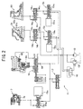
- FIG. 1 shows a transmission of a vehicle such as a motor vehicle.
- This transmission is made up of: a belt-type continuously (or steplessly) variable transmission mechanism 5 which is disposed between an output shaft 4 and an input shaft 3 to be connected to an engine 1 through a coupling mechanism 2; a switching mechanism 6 which switches between forward running and reverse running (hereinafter called forward/reverse switching mechanism 6) and which serves as a power transmission mechanism disposed on an input side of the continuously variable transmission mechanism 5; and a starting clutch 7 which is made up of a hydraulic clutch disposed on an output side of the continuously variable transmission mechanism 5.
- a belt-type continuously (or steplessly) variable transmission mechanism 5 which is disposed between an output shaft 4 and an input shaft 3 to be connected to an engine 1 through a coupling mechanism 2
- a switching mechanism 6 which switches between forward running and reverse running (hereinafter called forward/reverse switching mechanism 6) and which serves as a power transmission mechanism disposed on an input side of the continuously variable transmission mechanism 5
- a starting clutch 7 which is made up
- the continuously variable transmission mechanism 5 is made up of: a drive pulley 50 which is rotatably supported on the input shaft 3; a driven pulley 51 which is connected to the output shaft 4 so as not to rotate relative to the output shaft 4; and a metallic V-belt 52 which is wound around both the pulleys 50, 51.
- Each of the pulleys 50, 51 is made up of: a fixed flange 50a, 51a; a movable flange 50b, 51b which is axially movable relative to the fixed flange 50a, 51a; and a cylinder 50c, 51c which urges or pushes the movable flange 50b, 51b toward the fixed flange 50a, 51a.
- the forward/reverse switching mechanism 6 is constituted by a planetary gear mechanism which is made up of: a sun gear 60 which is connected to the input shaft 3; a ring gear 61 which is connected to the drive pulley 50; a carrier 62 which is rotatably supported by the input shaft 1; a planetary gear 63 which is rotatably supported by the carrier 62 and which is meshed with the sun gear 60 and the ring gear 61; a forward running clutch 64 which serves as a hydraulically operated friction element capable of connecting the input shaft 3 and the ring gear 61; and a reverse running brake 65 which serves as hydraulically operated friction element capable of fixing the carrier 62.
- the forward running clutch 64 When the forward running clutch 64 is engaged, the ring gear 61 rotates together with the input shaft 3, and the drive pulley 50 is rotated in the same direction as the input shaft 3 (i.e., forward running direction).
- the reverse running brake 65 When the reverse running brake 65 is engaged, on the other hand, the ring gear 61 is rotated in a direction opposite to that of the sun gear 60, and the drive pulley 50 is driven in a direction opposite to that of the input shaft 3 (i.e., in the reverse running direction).
- both the forward running clutch 64 and the reverse running brake 65 are released, the power transmission through the forward/reverse switching mechanism 6 is interrupted.
- the starting clutch 7 is connected to the output shaft 4.
- the output of the engine whose speed has been changed by the continuously variable transmission mechanism 5 is transmitted to a differential 9 through gear trains 8 on the output side of the starting clutch 7, whereby the driving force is transmitted to the left and right driving wheels (not illustrated) of the vehicle from the differential 9.
- the starting clutch 7 is released, the power transmission does not take place, and the transmission becomes a neutral state.
- an electric motor 10 is directly connected to the engine 1.
- the electric motor 10 performs power assisting at the time of acceleration, or the like, recovering of energy at the time of deceleration, and starting of the engine 1.
- the engine 1 is automatically stopped if some given conditions are satisfied, e.g.: that the brake is on; that an air conditioner is switched off; and a brake booster negative pressure is above a predetermined value; or the like. If the brake is subsequently off, the engine 1 is started by the electric motor 10, whereby the vehicle is started up from the state of the engine stopping.
- the hydraulic oil pressures in the cylinder 50c, 51c of each of the pulleys 50, 51 of the continuously variable transmission mechanism 5, in the forward running clutch 64, in the reverse running brake 65 and in the starting clutch 7 are controlled by a hydraulic circuit 11.
- the hydraulic circuit 11 is provided with a hydraulic oil pump 12 which is driven by the engine 1.
- the delivery pressure from this hydraulic oil pump 12 is regulated by a regulator 13 to a predetermined line pressure.
- the hydraulic oil pressures (pulley side-pressure) in each of the cylinders 50c, 51c of the drive pulley 50 and the driven pulley 51 can be regulated by each of the first and second pressure regulating valves 14 1 , 14 2 with the line pressure serving as a base pressure.
- Each of the first and second pressure regulating valves 14 1 , 14 2 is urged by a spring 14 1a , 14 2a toward the leftward open position, and is urged by the pulley side-pressure to be inputted into a left end oil chamber 14 1b , 14 2b toward the rightward closed position. Further, there are provided a first linear solenoid valve 15 1 for the first pressure regulating valve 14 1 and a second linear solenoid valve 15 2 for the second pressure regulating valve 14 2 . An output pressure from each of the first and second linear solenoid valves 15 1 , 15 2 is inputted into a right end oil chamber 14 1c , 14 2c of each of the pressure regulating valves 14 1 , 14 2 .
- each of the pulley side-pressures in the drive pulley 50 and the driven pulley 51 can be controlled by each of the first and second linear solenoid valves 15 1 , 15 2 .
- the output pressure which is the higher pressure between the output pressures of the first and second linear solenoid valves 15 1 , 15 2 is inputted into the regulator 13 through a changeover valve 16.
- an appropriate pulley side-pressure which does not give rise to slipping of the belt 52 is generated.
- Each of the first and second linear solenoid valves 15 1 , 15 2 is urged toward the leftward open position by a spring 15 1b , 15 2b and is also urged toward the rightward closed position by its own output pressure and an electromagnetic force of a solenoid 15 1a , 15 2a .
- a modulator pressure (a pressure which is lower than the line pressure by a certain value) from a modulator valve 17 serving as a basic pressure
- a hydraulic oil pressure in inverse proportion to the value of an electric current charged to the solenoid 15 1a , 15 2a is outputted.
- the starting clutch 7 there is connected an oil passage which supplies the modulator pressure, and a third linear solenoid valve 15 3 is interposed in this oil passage.
- the third linear solenoid valve 15 3 is urged toward the rightward closed position by a spring 15 3b and the hydraulic oil pressure of the starting clutch and is also urged toward the leftward open position by an electromagnetic force of the solenoid 15 3a .
- the hydraulic oil pressure of the starting clutch 7 varies in proportion to the value of the electric current charged to the solenoid 15 3a with the modulator pressure as the basic pressure.
- the modulator pressure is inputted into the forward running clutch 64 and the reverse running brake 65 through the manual valve 18.
- the manual valve 18 can be switched into the following five positions in a manner interlocked with a selector lever (not illustrated): i.e., "P" position for parking; “R” position for reverse running; “N” position for neutral state; “D” position for ordinary running; “S” position for sporty running; and “L” position for low-speed holding.
- the modulator pressure is supplied to the forward running clutch 64.
- the modulator pressure is supplied to the reverse running brake 65.
- the modulator pressure is supplied through an orifice 19.
- Each of the first through third linear solenoid valves 15 1 , 15 2 , 15 3 is controlled by a controller 20 (see FIG. 1) which is made up of an onboard (a vehicle-mounted) computer.
- the controller 20 receives the inputs of the following: i.e., the ignition pulses of the engine 1, signals indicating the negative suction pressure PB of the engine 1, and the throttle opening degree ⁇ ; a signal from a brake switch 21 which detects the degree or amount of depression of a brake pedal; a signal from a position sensor 22 which detects a selected position of the selector lever; a signal from a speed sensor 23 1 which detects a rotational speed, or a rotational frequency, of the drive pulley 50; a signal from a speed sensor 23 2 which detects the rotational speed of the driven pulley 51; a signal from a speed sensor 23 3 which detects the rotational speed on the output side of the starting clutch 7, i.e., the vehicle speed; and a signal from an oil temperature sensor 24 which detects
- the hydraulic oil pump 12 which serves as a hydraulic oil pressure source for the hydraulic circuit 11 is also stopped, whereby the hydraulic oil is drained from the hydraulic circuit 11.
- the hydraulic oil pump 12 which serves as a hydraulic oil pressure source for the hydraulic circuit 11 is also stopped, whereby the hydraulic oil is drained from the hydraulic circuit 11.
- a control mode of the starting clutch 7 at the time when the forward/reverse switching mechanism 6 has just attained the in-gear state, from a start transition mode in which an ineffective stroke of the starting clutch 7 is eliminated or minimized to a running mode in which the engaging force of the starting clutch 7 is increased.
- a creeping pressure a hydraulic oil pressure at which slipping of the starting clutch 7 does occur but at which a torque above an inertia of the vehicle can be transmitted.
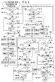
- the starting clutch 7 is controlled by the program shown in FIG. 3. This control is performed at a predetermined time interval, e.g., at a time interval of 10 msec.
- a discrimination is made as to whether a flag F1 has been set to "1" or not. Since the flag F1 has initially been reset to "0", a determination of "NO" is made at step S1.
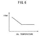
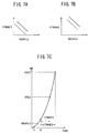
- the program then proceeds to step S2, where a timer value YTM1 is searched. Considering the delay in response to the increase or boosting in the hydraulic oil pressure, the timer value YTM1 is set, as shown in FIG.
- step S3 the remaining time TM1 of a subtraction type of first timer to YTM1
- step S4 the program proceeds to step S4 to perform the processing of discriminating the rise in the hydraulic oil pressure.
- FIG. 4 Details of the processing of discriminating the rise in the hydraulic oil pressure are shown in FIG. 4.
- steps S4-1, S4-2, S4-3 a discrimination is made respectively as to whether a flag F2, F3, F4 has been set to "1" or not. Since the flag F2, F3, F4 has initially been reset to "0", the program proceeds to step S4-4 to discriminate as to whether a flag F5 has been set to "1" or not.
- the flag F5 is a flag to be prepared in a subroutine work and is set to "1" if even only one of the ignition pulses is inputted within a predetermined time (e.g., 500 msec).
- step S4 the program proceeds to step S4-6. From the next time, the program proceeds from step S4-3 directly to step S4-6.
- a discrimination is made as to whether that rotational speed NE2PLS of the engine 1 which is calculated by the difference between the times of inputting two consecutive ignition pulses is larger than zero.
- the computation of NE2PSL is performed in a subroutine work. It is when NE2PSL calculated by the difference between the time of inputting a first ignition pulse and the time of inputting a second ignition pulse, which are inputted after the engine stopping, becomes larger than zero that a determination of "YES" is made at step S4-6.
- step S4-6 the program proceeds to step S4-7, where a timer value YTMNE1 which obtains or finds out the point of time at which the rotational speed NE of the engine 1 increases to a first predetermined speed YNE1 (e.g., 500 rpm) is searched. Then, the program proceeds to step S4-8, where a timer value YTMNE2 which obtains the point of time at which the rotational speed NE of the engine 1 increases to a second predetermined speed YNE2 (e.g., 900 rpm) is searched. As shown in FIGS.
- the values YTMNE1 and YTMNE2 are set such that the larger NE2PLS becomes, the shorter YTMNE1 and YTMNE2 become.
- reference character t1 denotes a point of time at which the first ignition pulse is inputted
- reference character t2 denotes a point of time at which the second ignition pulse is inputted.
- the rotational speed NE2PLS that is calculated from the difference in times of inputting both ignition pulses becomes considerably smaller than the actual rotational speed NE of the engine 1 at that point of time.
- YTMNE1 and YTMNE2 are set.
- step S4-4 the program proceeds from step S4-4 to step S4-9, where a discrimination is made as to whether the flag F6 has been set to "1" or not. Since the flag F6 has initially been reset to "0", a determination of "NO” is made at step S4-9. The program then proceeds to step S4-10, where a discrimination is made as to whether the rotational speed NE of the engine 1 obtained as an average value of a plurality of NE2PLS's is below a predetermined speed YNE (e.g., 500 rpm) or not.
- a predetermined speed YNE e.g. 500 rpm
- step S4-11 If a condition of NE ⁇ YNE is satisfied, the flag F6 is set to "1" at step S4-11 and the program then proceeds to step S4-12. From the next time, the program proceeds from step S4-9 directly to step S4-12, where a discrimination is made as to whether the value of NE2PLS at this time has become larger than the value NE2PLS1 at the previous time. It is when NE2PLS has changed for an increase for the first time after the vehicle start-up that a determination of "YES" is made at step S4-12.
- a searching for YTMNE1 and YTMNE2 is made at steps S4-13 and S4-14 with NE2PLS at this time serving as a parameter.
- YTMNE1 and YTMNE2 to be searched at steps S4-13 and S4-14 are set, as shown in dotted lines in FIGS. 7A and 7B, to become shorter than YTMNE1 and YTMNE2, as shown in solid lines, which are to be searched at steps S4-7 and S4-8.
- step S4-10 When a determination of "NO" is made at step S4-10, YTMNE1 and YTMNE2 are made to zero at steps S4-15 and S4-16. Once the searching for YTMNE1 and YTMNE2 is finished as noted above, the remaining times TMNE1 and TMNE2 of substraction type of first and second timers for discrimination of NE are set at steps S4-17 and S4-18 to YTMNE1 and YTMNE2, respectively. Then, at step S4-19, the flag F3 is set to "1", and the program proceeds to step S4-20. From the next time, the program proceeds from step S4-2 directly to step S4-20.
- an amount of change ⁇ IACT of an effective value IACT of electric current charged to the solenoid 15 3a of the third linear solenoid valve 15 3 is calculated.
- ⁇ IACT is calculated as a difference between a detected value of IACT at this time and an average value, e.g., of IACT detected three times before through IACT detected five times before.
- step S4-22 a discrimination is made as to whether an absolute value of ⁇ IACT has become smaller than a predetermined value Y ⁇ IACT1 (e.g., 3.1 mA) or not.
- a predetermined value Y ⁇ IACT1 e.g., 3.1 mA
- step S4-23 when a condition of
- the program then, proceeds to step S4-24. From the next time, the program proceeds from step S4-21 directly to step S4-24.
- a discrimination is made as to whether the remaining time TMNE1 of the first timer for discriminating NE has become zero or not, i.e., as to whether the rotational speed NE of the engine 1 has increased to the first predetermined speed YNE1 or not (see FIG. 7C). If the result of this discrimination is "YES”, a discrimination is made at step S4-25 as to whether the remaining time TM2 of a subtraction type of second timer has become zero or not.
- TM2 has initially been set to YTM2 at the beginning of vehicle start-up from the state of engine stopping.
- a discrimination is made at step S4-26 as to whether ⁇ IACT has exceeded a predetermined value Y ⁇ IACT2 (e.g., 12.4 mA) or not.
- TMNE1 0
- a discrimination is made at step S4-31 as to whether the rotational speed NDR of the drive pulley 50 has already exceeded a predetermined first speed YNDR1 (e.g., 500 rpm) or not. If a condition is NDR ⁇ YNDR1, a discrimination is made at step S4-32 as to whether the remaining time TMNE2 of the second timer for discriminating the NE has become zero or not, i.e., as to whether the rotational speed NE of the engine 1 has increased to the second predetermined speed YNE2 or not (see FIG. 7C).
- a predetermined first speed YNDR1 e.g. 500 rpm
- TM2 0
- a mode value ISMOD is set to "02" at step S4-34.
- the rise in the hydraulic oil pressure can be discriminated based on ⁇ IACT as explained hereinabove, i.e., based on the counter-electromotive force of the solenoid 15 3a of the third linear solenoid valve 15 3 .
- the third linear solenoid valve 15 3 will not be fully opened. The rise in the hydraulic oil pressure cannot therefore be discriminated based on the counter-electromotive force of the solenoid 15 3a .
- YTM3 e.g., 500 msec
- the initial pressure PSCA is set to a value substantially equal to a set load of a return spring 7a of the starting clutch 7. Even if the hydraulic oil pressure to the starting clutch 7 increases to the initial pressure PSCA, the starting clutch 7 only attains a state in which a non-effective stroke is eliminated down to the smallest extent possible and, thus, an engaging force will not occur. Therefore, even if the hydraulic oil pressure in the starting clutch 7 overshoots due to the rise in the hydraulic oil pressure in the hydraulic circuit 11, the starting clutch 7 will not be strongly engaged. Shocks will consequently not occur.
- the above-described YTM2 is set to such a time as, for example, 200 msec considering the time required for the pulley side-pressure to rise by the oil supply to the cylinder 50c, 51c of the drive pulley 50 or the driven pulley 51c. Further, due to the processing at steps S4-25 and S4-33, the setting to "1" of the flag F2 is prohibited until a lapse of time of YTM2 from the point of time of the vehicle start-up. The hydraulic oil pressure command value PSCCMD is thus held at the initial pressure PSCA. In this manner, by the engaging of the starting clutch 7 before the rise in the pulley side-pressure, the belt 52 can be prevented from slipping.
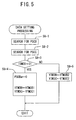
- step S8 When the hydraulic oil pressure in the hydraulic circuit 11 rises and the flag F2 is set to "1", the program proceeds to step S8 to perform the data setting processing. Details of this data setting processing are shown in FIG. 5 and its detailed explanation will be made hereinbelow.
- steps S8-1 and S8-2 an added value PSCB for the ineffective stroke eliminating pressure and an added value PSCC for the creeping pressure are respectively searched.
- PSCB and PSCC are set such that the lower the hydraulic oil temperature becomes, the higher they become, considering the delay in response to the increase in the hydraulic oil pressure. Values of PSCB and PSCC which correspond to the oil temperature at the present time are searched in the data table of PSCB and PSCC which has the oil temperature as a parameter.
- step S8-4 a preliminarily added value PSCBa for the ineffective stroke eliminating pressure is re-written to zero.
- a timer value YTM3B for judging the termination of the ineffective stroke eliminating pressure and a timer value YTM3C for judging the starting of the creeping pressure are set to first set values of YTM3B1 (e.g., 420 msec) and YTM3C1 (e.g., 400 msec), respectively.
- step S8-5 YTM3B and YTM3C are set to second set values of YTM3B2 (e.g., 470 msec) and YTM3C2 (e.g., 450 msec), respectively.
- step S9 a discrimination is made as to whether the remaining time TM3 in the third timer is above a predetermined set time YTM3A (e.g., 490 msec) or not, i.e., as to whether the time of lapse from the point of time of pressure rise is within YTM3 - YTM3A or not. If a condition of TM3 ⁇ YTM3A is satisfied, the hydraulic oil pressure command value PSCCMD is set at step S10 to a value obtained by adding PSCB and PSCBa to PSCA.
- a predetermined set time YTM3A e.g., 490 msec
- a discrimination is made at step S11 as to whether TM3 is above YTM3B or not, i.e., as to whether the time of lapse from the point of time of rise in the hydraulic oil pressure is within YTM3 - YTM3B or not. If a condition of TM3 ⁇ YTM3B is satisfied, the hydraulic oil pressure command value PSCCMD is set at step S12 to a value obtained by adding PSCB to PSCA.
- a discrimination is made at step S13 as to whether TM3 is above YTM3C or not, i.e., as to whether the time of lapse from the point of time of rise in the hydraulic oil pressure is within YTM3 - YTM3C or not. If a condition of TM3 ⁇ YTM3C is satisfied, the hydraulic oil pressure command value PSCCMD is set at step S14 to a value obtained by deducting, from a value obtained by adding PSCC to PSCA, that preliminarily deducted value PSCCa for the creeping pressure which is set in advance to a predetermined value.
- step S15 When a condition of TM3 ⁇ YTM3C has been satisfied, the flag F1 is set at step S15 to "1" and also, at step S16, the hydraulic oil pressure command value PSCCMD is set to a value obtained by adding PSCC to PSCA. From the next time, a determination of "YES” is made at step S1 and the program thus proceeds to step S17.
- step S17 a discrimination is made as to whether the remaining time TM1 in the first timer has become zero or not, i.e., as to whether the time of lapse from the point of time of setting the hydraulic oil pressure command value PSCCMD to PSCA + PSCC has become YTM1 or not.
- step S18 a discrimination is made at step S18 as to whether or not the range of the transmission is "N" or "P.” If the range is in a running range other than "N" and "P", a discrimination is made at step S19 as to whether the flag F9 has been set to "1" or not. Since the flag F9 has initially been set to "0”, a determination of "NO” is made at step S19, and the program proceeds to step S20. At step S20, a discrimination is made as to whether the rotational speed NDR of the drive pulley 50 has exceeded a second predetermined speed YNDR2 or not.
- step S21 the remaining time TM4 in a subtraction type of fourth timer is set at step S21 to a predetermined time YTM4.
- the program then proceeds to step S16, where the hydraulic oil pressure command value PSCCMD is held at PSCA + PSCC.
- PSCC is set such that the value obtained by adding the initial value PSCA to PSCC becomes the creeping pressure.
- PSCB is set to a value larger than PSCC.
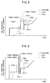
- PSCCMD When the lapse of time has exceeded YTM3 - YTM3C, PSCCMD is switched to PSCA + PSCC, i.e., to the creeping pressure.
- the effective electric current value IACT of the solenoid 15 3a lowers at a good response from the electric current value corresponding to the ineffective stroke eliminating pressure down to the electric current value corresponding to the creeping pressure.
- the actual clutch pressure PSC of the starting clutch 7 is then increased to the creeping pressure without giving rise to overshooting before the lapse of time YTM1 from the point of time at which PSCCMD was switched to the creeping pressure.
- PSCCMD When the rise in the hydraulic oil pressure is discriminated based on the rotational speed NDR of the drive pulley 50 and the rotational speed NE of the engine 1, and ISMOD is consequently set to "02", PSCCMD is switched, as shown in FIG. 9, to a value of PSCA + PSCB + PSCBa , i.e., to a value higher than the ineffective stroke eliminating pressure until the time of lapse from the point of time of discriminating the rise in the hydraulic oil pressure becomes YTM3 - YTM3A. When the time of lapse has exceeded YTM3 - YTM3A, PSCCMD is switched to PSCA + PSCB, i.e., the ineffective stroke eliminating pressure.
- ISMOD it is when there is a residual pressure in the hydraulic circuit 11 that ISMOD is set to "02". Since the actual hydraulic oil pressure PSC of the starting clutch 7 increases at a relatively good response, YTM3B2 is set to a value larger than YTM3B1 to thereby shorten the time to hold PSCCMD at the ineffective stroke eliminating pressure.
- PSCCMD Until the forward/reverse switching mechanism 6 becomes the in-gear state, PSCCMD is held at the creeping pressure, thereby preventing the occurrence of shocks by a sudden rise in the driving torque of the driving wheels of the vehicle at the time of gearing in.
- whether the forward/reverse switching mechanism 6 has become the in-gear state or not can be discriminated by checking whether the deviation between the rotational speed NE of the engine 1 and the rotational speed NDR of the drive pulley 50 has fallen below a predetermined value or not.
- the rotational speed of the engine 1 rapidly increases.
- the discrimination of the in-gear state is made based only on the rotational speed NDR of the drive pulley 50.
- a discrimination is made at step S20 as to whether the rotational speed NDR of the drive pulley 50 has exceeded a predetermined second speed YNDR2 (e.g., 700 rpm) or not.
- a change limit value ⁇ PLMT on the positive (plus) side of the hydraulic oil pressure per one time is set at step S26 to an ordinary annealing value Y ⁇ PLMTN (e.g., 0.5 kg/cm 2 ). If TM4 ⁇ 0, ⁇ PLMT is set at step S27 to a value Y ⁇ PLMTS (e.g., 0.25 kg/cm 2 ) which is smaller than Y ⁇ PLMTN. Then, at step S28, a discrimination is made as to whether an absolute value of the deviation between PSCN and PSCLMT is above ⁇ PLMT or not.
- Y ⁇ PLMTN e.g., 0.5 kg/cm 2
- PSCLMT is re-written at step S29 to a value which is obtained by adding ⁇ PLMT to the preceding value of PSCLMT. If the deviation is below ⁇ PLMT, PSCLMT is re-written at step S30 to PSCN. Further, if a condition of PSCN ⁇ PSCLMT is satisfied, a discrimination is made at step S31 as to whether or not an absolute value of the deviation between PSCN and PSCLMT is above a predetermined upper limit value ⁇ PLMTM on the negative (minus) side (e.g., 0.5 kg/cm 2 ) of the hydraulic oil pressure.
- ⁇ PLMTM on the negative (minus) side (e.g., 0.5 kg/cm 2 ) of the hydraulic oil pressure.
- PSCLMT is re-written at step S32 to a value which is obtained by deducting ⁇ PLMTM from the preceding value of PSCLMT. If the deviation is below ⁇ PLMTM, PSCLMT is re-written at step S30 to PSCN as described hereinabove. In addition, at step S33, the hydraulic oil pressure command value PSCCMD is set to PSCLMT.
- the amount of increase (or increment) per time of the hydraulic oil pressure command value PSCCMD becomes the ordinary annealing value Y ⁇ PLMTN.
- the amount of increment per time of PSCCMD is limited to Y ⁇ PLMS which is smaller than the ordinary annealing value.
- PSCCMD i.e., the speed of increase in the hydraulic oil pressure in the starting clutch 7 is limited to a relatively low speed.
- the pulley side-pressure shall not be made larger than is required as compared with the transmission torque at the point of time in question. Therefore, in the start-up transition mode, the pulley side-pressure is made relatively low, and the pulley side-pressure is increased to suit the increase in the hydraulic oil pressure for the starting clutch 7 as a result of switching to the running mode. However, there are cases where the hydraulic oil pressure in the hydraulic circuit 11 has not been completely increased to the line pressure even at the time of switching to the running mode.
- the above-described YTM4 is set to 90 msec, for example.
- the hydraulic oil pressure in the starting clutch can be prevented from overshooting beyond the creeping pressure at the time of pressure rise in the hydraulic circuit, whereby the occurrence of shocks can be prevented.
- the hydraulic oil pressure in the starting clutch can be increased to the creeping pressure at a good response. The vehicle start-up from the state of engine stopping can be performed smoothly at a good
- a hydraulic oil pressure (PSC) in a starting clutch (7) sometimes overshoots beyond a creeping pressure as a result of a rise in the hydraulic oil pressure in the hydraulic circuit, resulting in shocks.
- the command value is made higher than the creeping pressure for a predetermined period of time (i.e., for the period of YTM3 - YTM3B1), and is thereafter made to the creeping pressure.
Landscapes
- Physics & Mathematics (AREA)
- Fluid Mechanics (AREA)
- Engineering & Computer Science (AREA)
- General Engineering & Computer Science (AREA)
- Mechanical Engineering (AREA)
- Hydraulic Clutches, Magnetic Clutches, Fluid Clutches, And Fluid Joints (AREA)
- Control Of Driving Devices And Active Controlling Of Vehicle (AREA)
- Control Of Vehicle Engines Or Engines For Specific Uses (AREA)
- Control Of Transmission Device (AREA)
Applications Claiming Priority (2)
| Application Number | Priority Date | Filing Date | Title |
|---|---|---|---|
| JP20643299A JP3432773B2 (ja) | 1999-07-21 | 1999-07-21 | アイドル運転停止車両における発進クラッチの制御装置 |
| JP20643299 | 1999-07-21 |
Publications (3)
| Publication Number | Publication Date |
|---|---|
| EP1070870A2 true EP1070870A2 (fr) | 2001-01-24 |
| EP1070870A3 EP1070870A3 (fr) | 2002-01-09 |
| EP1070870B1 EP1070870B1 (fr) | 2003-11-26 |
Family
ID=16523289
Family Applications (1)
| Application Number | Title | Priority Date | Filing Date |
|---|---|---|---|
| EP00114531A Expired - Lifetime EP1070870B1 (fr) | 1999-07-21 | 2000-07-06 | Dispositif de commande d'un embrayage de démarrage dans un véhicule à fonction arrêt moteur en ralenti |
Country Status (5)
| Country | Link |
|---|---|
| US (1) | US6344016B1 (fr) |
| EP (1) | EP1070870B1 (fr) |
| JP (1) | JP3432773B2 (fr) |
| CA (1) | CA2313575C (fr) |
| DE (1) | DE60006747T2 (fr) |
Cited By (6)
| Publication number | Priority date | Publication date | Assignee | Title |
|---|---|---|---|---|
| EP1344673A3 (fr) * | 2002-03-11 | 2005-11-30 | JATCO Ltd | Système hydraulique pour transmission automatique pour véhicule avec commande d'arrêt en position de ralenti |
| EP1265009A3 (fr) * | 2001-06-04 | 2006-03-08 | JATCO Ltd | Système hydraulique pour transmission automatique pour véhicule avec commande d'arrêt en position de ralenti |
| EP1279868A4 (fr) * | 2001-03-02 | 2006-03-08 | Jatco Ltd | Unite de commande pour transmissions automatiques |
| EP1445514A3 (fr) * | 2003-02-06 | 2008-07-30 | JATCO Ltd | Dispositif hydraulique de commande de passage de vitesses pour transmission automatique de véhicule |
| CN105164444A (zh) * | 2013-03-01 | 2015-12-16 | Wpt动力有限公司 | 单调耦接组件接合 |
| WO2015173621A3 (fr) * | 2014-05-14 | 2016-04-14 | Toyota Jidosha Kabushiki Kaisha | Système de commande pour embrayage |
Families Citing this family (18)
| Publication number | Priority date | Publication date | Assignee | Title |
|---|---|---|---|---|
| JP3653028B2 (ja) * | 2001-10-17 | 2005-05-25 | 本田技研工業株式会社 | 車両用動力伝達制御装置 |
| JP3712193B2 (ja) * | 2001-12-10 | 2005-11-02 | 本田技研工業株式会社 | 動力伝達装置における摩擦係合要素の係合制御方法 |
| JP4269999B2 (ja) | 2003-06-30 | 2009-05-27 | トヨタ自動車株式会社 | 負荷要素の状態検出装置 |
| JP4102341B2 (ja) * | 2004-08-17 | 2008-06-18 | ジヤトコ株式会社 | 自動変速機の制御装置 |
| DE102007003726A1 (de) | 2007-01-25 | 2008-07-31 | Zf Friedrichshafen Ag | Verfahren zum Betreiben eines Fahrzeugantriebsstranges |
| US9097337B2 (en) * | 2007-10-26 | 2015-08-04 | GM Global Technology Operations LLC | Method and apparatus to control hydraulic line pressure in an electro-mechanical transmission |
| DE102009053284B4 (de) * | 2009-11-13 | 2024-08-22 | Dr. Ing. H.C. F. Porsche Aktiengesellschaft | Verfahren zum Starten einer Brennkraftmaschine |
| JP5396374B2 (ja) * | 2010-11-26 | 2014-01-22 | ジヤトコ株式会社 | 車両の制御装置 |
| JP5346998B2 (ja) * | 2011-07-14 | 2013-11-20 | 本田技研工業株式会社 | 車両の制御装置 |
| US8733072B2 (en) | 2011-11-04 | 2014-05-27 | Briggs & Stratton Corporation | Starter system for an engine |
| US8857138B2 (en) * | 2011-11-04 | 2014-10-14 | Briggs & Stratton Corporation | Starter system for an engine |
| US9221451B2 (en) | 2012-05-17 | 2015-12-29 | Toyota Motor Engineering & Manufacturing North America, Inc. | Systems and methods for increasing fuel efficiency |
| US9689493B2 (en) | 2013-05-31 | 2017-06-27 | GM Global Technoloogy Operations LLC | System and method for minimal draindown in CVT |
| JP6782657B2 (ja) | 2017-03-29 | 2020-11-11 | 本田技研工業株式会社 | クラッチ制御装置 |
| WO2020017178A1 (fr) | 2018-07-19 | 2020-01-23 | 本田技研工業株式会社 | Dispositif de commande d'embrayage |
| WO2020026591A1 (fr) | 2018-08-01 | 2020-02-06 | 本田技研工業株式会社 | Appareil de commande d'embrayage |
| CN112555298B (zh) * | 2020-12-09 | 2022-05-06 | 江苏新能源汽车研究院有限公司 | 一种混合动力新能源车辆用离合器的优化型充油控制方法 |
| CN113339423B (zh) * | 2021-05-31 | 2023-04-07 | 重庆青山工业有限责任公司 | 一种防止湿式dct离合器输出压力过大的方法 |
Family Cites Families (8)
| Publication number | Priority date | Publication date | Assignee | Title |
|---|---|---|---|---|
| JPS6218336A (ja) * | 1985-07-17 | 1987-01-27 | Nissan Motor Co Ltd | 自動変速機のクリ−プ防止装置 |
| JPH05106720A (ja) * | 1991-09-27 | 1993-04-27 | Suzuki Motor Corp | 無段変速機のクラツチ制御方法 |
| JP3775012B2 (ja) * | 1997-08-29 | 2006-05-17 | アイシン・エィ・ダブリュ株式会社 | 車両用ハイブリッド駆動装置 |
| JP3341659B2 (ja) * | 1997-12-05 | 2002-11-05 | 日産自動車株式会社 | ハイブリッド車の制御装置 |
| JP3214427B2 (ja) * | 1997-12-12 | 2001-10-02 | トヨタ自動車株式会社 | ハイブリッド車の駆動制御装置 |
| JP4227211B2 (ja) * | 1998-02-26 | 2009-02-18 | いすゞ自動車株式会社 | 電子制御クラッチを備えた車両の始動装置 |
| DE69926269T2 (de) * | 1998-04-17 | 2006-05-04 | Toyota Jidosha K.K., Toyota | Steuerungsvorrichtung zur Startwiederholung eines Fahrzeugsmotors |
| US5980428A (en) * | 1998-11-13 | 1999-11-09 | Eaton Corporation | Vehicle launch automated master clutch control |
-
1999
- 1999-07-21 JP JP20643299A patent/JP3432773B2/ja not_active Expired - Lifetime
-
2000
- 2000-07-05 CA CA002313575A patent/CA2313575C/fr not_active Expired - Fee Related
- 2000-07-06 DE DE60006747T patent/DE60006747T2/de not_active Expired - Lifetime
- 2000-07-06 EP EP00114531A patent/EP1070870B1/fr not_active Expired - Lifetime
- 2000-07-19 US US09/619,766 patent/US6344016B1/en not_active Expired - Lifetime
Non-Patent Citations (1)
| Title |
|---|
| None |
Cited By (8)
| Publication number | Priority date | Publication date | Assignee | Title |
|---|---|---|---|---|
| EP1279868A4 (fr) * | 2001-03-02 | 2006-03-08 | Jatco Ltd | Unite de commande pour transmissions automatiques |
| EP1265009A3 (fr) * | 2001-06-04 | 2006-03-08 | JATCO Ltd | Système hydraulique pour transmission automatique pour véhicule avec commande d'arrêt en position de ralenti |
| EP1344673A3 (fr) * | 2002-03-11 | 2005-11-30 | JATCO Ltd | Système hydraulique pour transmission automatique pour véhicule avec commande d'arrêt en position de ralenti |
| EP1445514A3 (fr) * | 2003-02-06 | 2008-07-30 | JATCO Ltd | Dispositif hydraulique de commande de passage de vitesses pour transmission automatique de véhicule |
| CN105164444A (zh) * | 2013-03-01 | 2015-12-16 | Wpt动力有限公司 | 单调耦接组件接合 |
| EP2962007A4 (fr) * | 2013-03-01 | 2016-12-07 | Wpt Power Corp | Enclenchement d'un ensemble de couplage monotone |
| CN105164444B (zh) * | 2013-03-01 | 2017-09-12 | Wpt动力有限公司 | 单调耦接组件接合 |
| WO2015173621A3 (fr) * | 2014-05-14 | 2016-04-14 | Toyota Jidosha Kabushiki Kaisha | Système de commande pour embrayage |
Also Published As
| Publication number | Publication date |
|---|---|
| DE60006747D1 (de) | 2004-01-08 |
| JP3432773B2 (ja) | 2003-08-04 |
| EP1070870A3 (fr) | 2002-01-09 |
| JP2001032863A (ja) | 2001-02-06 |
| US6344016B1 (en) | 2002-02-05 |
| CA2313575C (fr) | 2007-10-16 |
| EP1070870B1 (fr) | 2003-11-26 |
| CA2313575A1 (fr) | 2001-01-21 |
| DE60006747T2 (de) | 2004-05-19 |
Similar Documents
| Publication | Publication Date | Title |
|---|---|---|
| EP1070870B1 (fr) | Dispositif de commande d'un embrayage de démarrage dans un véhicule à fonction arrêt moteur en ralenti | |
| EP0925980B1 (fr) | Système de commande d'entraínement pour véhicules et procédé de commande | |
| KR100644735B1 (ko) | 무단 변속기의 변속비 제어 장치 및 그 방법 | |
| EP1070868B1 (fr) | Dispositif de commande d'un embrayage de démarrage dans un véhicule à fonction arrêt moteur en ralenti | |
| EP0832778B1 (fr) | Commande d'embrayage d'un véhicule | |
| EP0430675A2 (fr) | Transmission continue de vitesse avec convertisseur de couple | |
| US5733220A (en) | Working fluid pressure control system for startup friction elements of R TO N TO D shifts | |
| EP1070869B1 (fr) | Dispositif de commande d'un embrayage de démarrage dans un véhicule à fonction arrêt moteur en ralenti | |
| EP1355089B1 (fr) | Système de commande hydraulique pour une transmission automatique | |
| EP1070885B1 (fr) | Appareil pour régler la poussée latérale d'une poulie d'une transmission à variation de vitesse continue dans un véhicule avec fonction d' arrêt du moteur fonctionnant au ralenti | |
| JP2004125037A (ja) | 無段変速機の変速制御装置 | |
| CA2313595C (fr) | Appareil de commande de l'embrayage de mise en mouvement d'un vehicule muni d'une fonction d'arret au ralenti moteur | |
| JP4132565B2 (ja) | アイドル運転停止車両における発進クラッチの制御装置 | |
| JP2001330126A (ja) | ベルト式無段変速機の制御装置 | |
| JP3862929B2 (ja) | アイドル運転停止車両における発進クラッチの制御装置 | |
| JP3532498B2 (ja) | アイドル運転停止車両における無段変速機のプーリ側圧制御装置 | |
| US12472929B2 (en) | Electric power generation load reduction method and electric power generation load reduction apparatus for internal combustion engine for vehicle | |
| EP3348877A1 (fr) | Dispositif pour commander un variateur de véhicule | |
| JP2003278901A (ja) | 自動変速機の変速油圧装置 | |
| JP3201200B2 (ja) | クラッチの発進制御装置 | |
| JP2906565B2 (ja) | 車両用無段変速機の変速比制御装置 | |
| JPH0723059B2 (ja) | 無段変速機および副変速機を備えた車両用変速機の制御方法 | |
| JPH08282337A (ja) | エンジンの制御装置 | |
| JPH01216164A (ja) | 無段変速機の制御装置 |
Legal Events
| Date | Code | Title | Description |
|---|---|---|---|
| PUAI | Public reference made under article 153(3) epc to a published international application that has entered the european phase |
Free format text: ORIGINAL CODE: 0009012 |
|
| AK | Designated contracting states |
Kind code of ref document: A2 Designated state(s): AT BE CH CY DE DK ES FI FR GB GR IE IT LI LU MC NL PT SE Kind code of ref document: A2 Designated state(s): DE FR GB |
|
| AX | Request for extension of the european patent |
Free format text: AL;LT;LV;MK;RO;SI |
|
| PUAL | Search report despatched |
Free format text: ORIGINAL CODE: 0009013 |
|
| AK | Designated contracting states |
Kind code of ref document: A3 Designated state(s): AT BE CH CY DE DK ES FI FR GB GR IE IT LI LU MC NL PT SE |
|
| AX | Request for extension of the european patent |
Free format text: AL;LT;LV;MK;RO;SI |
|
| 17P | Request for examination filed |
Effective date: 20020607 |
|
| AKX | Designation fees paid |
Free format text: DE FR GB |
|
| GRAH | Despatch of communication of intention to grant a patent |
Free format text: ORIGINAL CODE: EPIDOS IGRA |
|
| GRAS | Grant fee paid |
Free format text: ORIGINAL CODE: EPIDOSNIGR3 |
|
| GRAA | (expected) grant |
Free format text: ORIGINAL CODE: 0009210 |
|
| AK | Designated contracting states |
Kind code of ref document: B1 Designated state(s): DE FR GB |
|
| REG | Reference to a national code |
Ref country code: GB Ref legal event code: FG4D |
|
| REF | Corresponds to: |
Ref document number: 60006747 Country of ref document: DE Date of ref document: 20040108 Kind code of ref document: P |
|
| REG | Reference to a national code |
Ref country code: IE Ref legal event code: FG4D |
|
| ET | Fr: translation filed | ||
| PLBE | No opposition filed within time limit |
Free format text: ORIGINAL CODE: 0009261 |
|
| STAA | Information on the status of an ep patent application or granted ep patent |
Free format text: STATUS: NO OPPOSITION FILED WITHIN TIME LIMIT |
|
| 26N | No opposition filed |
Effective date: 20040827 |
|
| REG | Reference to a national code |
Ref country code: IE Ref legal event code: MM4A |
|
| PGFP | Annual fee paid to national office [announced via postgrant information from national office to epo] |
Ref country code: FR Payment date: 20130724 Year of fee payment: 14 Ref country code: GB Payment date: 20130703 Year of fee payment: 14 |
|
| GBPC | Gb: european patent ceased through non-payment of renewal fee |
Effective date: 20140706 |
|
| REG | Reference to a national code |
Ref country code: FR Ref legal event code: ST Effective date: 20150331 |
|
| PG25 | Lapsed in a contracting state [announced via postgrant information from national office to epo] |
Ref country code: FR Free format text: LAPSE BECAUSE OF NON-PAYMENT OF DUE FEES Effective date: 20140731 Ref country code: GB Free format text: LAPSE BECAUSE OF NON-PAYMENT OF DUE FEES Effective date: 20140706 |
|
| REG | Reference to a national code |
Ref country code: DE Ref legal event code: R084 Ref document number: 60006747 Country of ref document: DE |
|
| PGFP | Annual fee paid to national office [announced via postgrant information from national office to epo] |
Ref country code: DE Payment date: 20190625 Year of fee payment: 20 |
|
| REG | Reference to a national code |
Ref country code: DE Ref legal event code: R071 Ref document number: 60006747 Country of ref document: DE |