EP1070889A2 - Soupape de contrôle axiale - Google Patents
Soupape de contrôle axiale Download PDFInfo
- Publication number
- EP1070889A2 EP1070889A2 EP00115784A EP00115784A EP1070889A2 EP 1070889 A2 EP1070889 A2 EP 1070889A2 EP 00115784 A EP00115784 A EP 00115784A EP 00115784 A EP00115784 A EP 00115784A EP 1070889 A2 EP1070889 A2 EP 1070889A2
- Authority
- EP
- European Patent Office
- Prior art keywords
- control valve
- pressure
- valve
- ring
- thread
- Prior art date
- Legal status (The legal status is an assumption and is not a legal conclusion. Google has not performed a legal analysis and makes no representation as to the accuracy of the status listed.)
- Withdrawn
Links
- 239000012528 membrane Substances 0.000 claims abstract description 43
- 238000007789 sealing Methods 0.000 claims description 61
- 230000000670 limiting effect Effects 0.000 claims description 19
- 238000009434 installation Methods 0.000 claims description 17
- 238000005259 measurement Methods 0.000 claims description 17
- 239000005060 rubber Substances 0.000 claims description 15
- 230000007423 decrease Effects 0.000 claims description 12
- 238000013459 approach Methods 0.000 claims description 10
- 230000033228 biological regulation Effects 0.000 claims description 10
- 125000006850 spacer group Chemical group 0.000 claims description 7
- 230000008878 coupling Effects 0.000 claims description 5
- 238000010168 coupling process Methods 0.000 claims description 5
- 238000005859 coupling reaction Methods 0.000 claims description 5
- 230000006835 compression Effects 0.000 claims description 4
- 238000007906 compression Methods 0.000 claims description 4
- 210000001061 forehead Anatomy 0.000 claims description 3
- 238000011010 flushing procedure Methods 0.000 claims description 2
- 239000012535 impurity Substances 0.000 claims description 2
- 230000007704 transition Effects 0.000 claims 3
- 238000009530 blood pressure measurement Methods 0.000 claims 1
- 210000003128 head Anatomy 0.000 claims 1
- 230000008901 benefit Effects 0.000 description 16
- 230000008859 change Effects 0.000 description 8
- 230000004888 barrier function Effects 0.000 description 6
- 230000003068 static effect Effects 0.000 description 4
- 230000007246 mechanism Effects 0.000 description 3
- 239000004033 plastic Substances 0.000 description 3
- 238000011144 upstream manufacturing Methods 0.000 description 3
- 238000001816 cooling Methods 0.000 description 2
- 238000010438 heat treatment Methods 0.000 description 2
- 238000004519 manufacturing process Methods 0.000 description 2
- 239000002184 metal Substances 0.000 description 2
- 230000001681 protective effect Effects 0.000 description 2
- 238000009423 ventilation Methods 0.000 description 2
- 101100217199 Arabidopsis thaliana ARV2 gene Proteins 0.000 description 1
- 229910001369 Brass Inorganic materials 0.000 description 1
- 238000004378 air conditioning Methods 0.000 description 1
- 239000010951 brass Substances 0.000 description 1
- 230000001419 dependent effect Effects 0.000 description 1
- 238000006073 displacement reaction Methods 0.000 description 1
- 238000005516 engineering process Methods 0.000 description 1
- 239000000463 material Substances 0.000 description 1
- 230000036961 partial effect Effects 0.000 description 1
- 238000007639 printing Methods 0.000 description 1
- 230000002829 reductive effect Effects 0.000 description 1
- 230000000630 rising effect Effects 0.000 description 1
- 229910001220 stainless steel Inorganic materials 0.000 description 1
- 239000010935 stainless steel Substances 0.000 description 1
- 238000013024 troubleshooting Methods 0.000 description 1
- 238000013022 venting Methods 0.000 description 1
Images


Classifications
-
- F—MECHANICAL ENGINEERING; LIGHTING; HEATING; WEAPONS; BLASTING
- F16—ENGINEERING ELEMENTS AND UNITS; GENERAL MEASURES FOR PRODUCING AND MAINTAINING EFFECTIVE FUNCTIONING OF MACHINES OR INSTALLATIONS; THERMAL INSULATION IN GENERAL
- F16K—VALVES; TAPS; COCKS; ACTUATING-FLOATS; DEVICES FOR VENTING OR AERATING
- F16K1/00—Lift valves or globe valves, i.e. cut-off apparatus with closure members having at least a component of their opening and closing motion perpendicular to the closing faces
- F16K1/12—Lift valves or globe valves, i.e. cut-off apparatus with closure members having at least a component of their opening and closing motion perpendicular to the closing faces with streamlined valve member around which the fluid flows when the valve is opened
- F16K1/123—Lift valves or globe valves, i.e. cut-off apparatus with closure members having at least a component of their opening and closing motion perpendicular to the closing faces with streamlined valve member around which the fluid flows when the valve is opened with stationary valve member and moving sleeve
Definitions
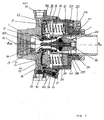
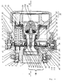
- the invention relates to an axial control valve with a Diaphragm and spring is operated and a simple manual Shutdown on the hydraulic way of flow as well as a mechanical of the connectable measuring and drain valve enables.
- valve plate and seat can be exchanged without Disassembly of the valve housing possible.
- This controller also enables other functions. This are besides the already mentioned barrier still the measurement of the Flow, opening limitation, emptying and the Regulation of differential pressure and / or flow. A extended, more expensive version also enables Throttling and shutting off the valve without doing that Change the default.
- the controller is particularly suitable for controlling the rising pipes in central heating systems, in the Air conditioning or cooling and in house stations District heating supply or cooling.
- the invention solves one or more of the following technical Problems:
- the manual shut-off should be as simple and inexpensive as possible.
- the shut-off is implemented with the help of movable axes which act on the movable valve seat through the housing wall.
- a bad feature of the known solutions is that because of the central shut-off, at least three axles and a shut-off wheel that presses on all three axles at the same time are required.
- Each individual axis must be sealed with a seal that is suitable for moving parts. However, such seals are very expensive.
- the setting of the differential pressure or the flow should be simple and cheap.
- the setting of the spring force is carried out with at least three movable axes, which press against a spring through the housing and enable continuous adjustment in a certain range.
- the weakness of known designs lies in the large number of parts and in the sensitive sealing of these.
- the adjusting nut is easily accessible, which allows for easy deliberate manipulation of the setting. It is possible to seal the mother, but this is not sufficient in all cases.
- the hand lock with the help of an integrated Three-way valves should also be possible in the flow controller.
- the problem is that if there is none Flow there, the pressures on both sides of the membrane can compensate and thus prevent the barrier. This is because with known axial valves the diaphragm only based on the membrane plate and is not attached.
- the Shut-off pressure in the closing direction on the plus side of the Membrane acts, so can even the minus side of the membrane if they are not firmly attached to the membrane disc is.
- the controller should enable several functions at the same time, whereby it should be as small and short as possible, but with high capacity and low sound level.
- the measuring connections should come together in one place from the Housing are guided and closed with a valve become.
- the ventilation of the plus chamber should be done with a single Bleed screw may be possible with horizontal or vertical installation.
- a controller should be possible from the same components of the differential pressure or flow, or to build one combined flow / differential pressure regulator.
- the total permanent pressure loss and pressure consumption Regulation of the controller should be as small as possible at highly precise regulation.
- the springs which are in the form of a ring in the axial regulator installed, tend to tip over during assembly if they are not are installed very precisely without transverse deviations and Charges. If both housing halves are threaded be assembled and mutually opposed during assembly turn, it is very difficult to correctly position the springs in the ring to achieve.
- the seal in the valve plate of the axial valve should run reliably.
- the well-known version includes a valve plate, a valve insert, a housing and a screw.
- the problem is that the screw head too must write.
- such a seal is not so secure than with a rubber seal.
- the installation of a rubber seal is but problematic due to lack of space and execution can make it more expensive.
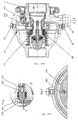
- the axial regulator In the axial regulator is in the impulse tube, which is the pressure of the medium leads into the minus chamber and the minus side of the membrane Aslock valve installed.
- the minus chamber In the minus chamber is one Exhaust valve installed. Until the shut-off valve opens and that If the exhaust valve is closed, the controller works normally. But if you want to shut off the flow manually, it closes the shut-off valve and opens the outlet valve. The pressure in the minus chamber falls to zero and the pressure of the plus Chamber from the plus side of the membrane closes tightly Control valve. An even better and cheaper solution to the The problem is the use of a three-way valve that is integrated into the housing of the control valve.
- a simple, small three-way valve integrated in the housing is much cheaper than three sealed axles with one large lock nut.
- the external seal is only static Seal executed.
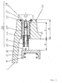
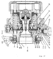
- the setting of the spring force is included in the axial control valve With the help of three fixed setting elements of the same size, the press on the spring.
- the adjusting disks can unscrewed and replaced.
- a cheap cartridge with a static seal replaces that expensive metal axle with a dynamic seal and larger Adjusting nut.
- the washers can be used during operation and under Pressure to be changed because the three-way valve Empty the minus chamber with the springs and adjusting elements can.
- the setting is graded in as many steps as much you have different places.
- Adjusting and changing the setting is less more comfortable than the one with movable axes and one Adjusting nut.
- an additional change is only very rarely required
- a shut-off screw In the impulse line, which the plus pressure from the measuring nozzle in the measuring chamber leads, a shut-off screw is installed, which only seals to the outside with a thread. A full one Sealing to the outside ensures a stopper with a static seal. Before the barrier is shut off away.
- In the housing is in the hole for the medium supply in the A three-way valve attached from a drain valve Check valve with a spring with a stopper an opening needle is composed. If the Is completely screwed in, then presses the Open the needle on the plate in the check valve and hold it in the open position. The medium can through the Check valve flow. But if you have the stopper for turns about two turns, the opening needle moves away from the plate of the check valve, which is under spring force and pressure influence closes.
- the drain valve can be installed between the company. So only one is sufficient for the entire installation.
- the adjustment elements are attached to a diameter that smaller than the diameter of the counter flanges. That is why in corresponding additional bores to the counter flange attached, through which the adjusting elements are screwed can.
- the advantage is a small diameter of the Control valve. Disadvantage is that the flange is not is standard, but can be supplied with the valve got to.
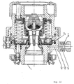
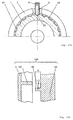
- the controller is an aerodynamically shaped when entering Measuring nozzle installed, regardless of the location of the Valve plates works.
- the decrease in the plus and minus Printing is done through circular gaps that are attached so are that the flow geometry does not change.
- the gap runs along the entire circumference and thus takes the pressure off from all points on the circumference of the entire pipe.
- the edge of the gap is sharp and with the greatest accuracy manufactured.
- the gap is also very narrow and the edge shaped so that it has no additional disturbances and eddies caused.
- an appropriate fixed insert is placed in the nozzle install. So you can the the nozzle characteristics Adjust the intended flow.
- the smooth and narrow circular gap balances the influence of Turbulence in individual parts of the pipe cross section.
- the shape of the nozzle, as well as the location of the circular column are selected so that the flow geometry is very different changes slightly. This means that even with large flows achieved much higher measurement accuracy than known ones Versions, but also for very small ones approximately the same.
- the knife can only be installed in a manual shut-off valve, since with an automatic controller the position of the plate is not is fixed and therefore a measurement is not possible.
- the holes for the pressure decrease are relatively small and have the Entry into a relatively raw cast or forged Housing wall. That's why the geometry isn't with everyone Product series the same. Because of the small size, they are very nice subject to local turbulence in the pipe cross-section.
- the geometry of the jet on the plate and at the openings changes and significantly affects the accuracy of the Measurement.
- the measurement depends on the position of the valve plate must be known exactly. Tolerance deviations in the Manufacture of the plate and mechanism for the Position reading can greatly affect accuracy.
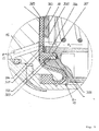
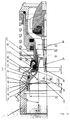
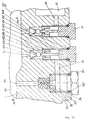
- the decreases in the plus and minus pressure are in the Measuring chamber executed and separated with a rubber sleeve.
- a ball valve is attached to the measuring chamber, which at the same time serves the filling.
- the tap turns a combined Measuring tube introduced.
- the inside measures the minus pressure and the sealing sleeve must pierce in the measuring chamber and in enter the area of minus pressure.
- Around the inner tube is a house that is in the area of plus pressure before Reach in the rubber cuff.
- the plus pressure will continue as (dp-) pulse from the measuring chamber through the pulse hole on the Diaphragm of the differential pressure regulator, or as (V +) Impulse on the diaphragm of the flow controller.
- the barrier and seal to the outside against the big one Pressure is achieved with a ball valve that is only in the Measurement opens.
- the rubber sleeve just needs the difference between the plus and seal negative pressure, which is relatively small (20 to 30 kPa) is. Absolute tightness is not required. Also if a few drops come out of the seal, it is not Problem because they stay inside.
- the hole for the plus pressure is also used as Pulse hole used for the control and as a filling hole. Instead of three holes, only one is required.
- shut-off and throttling is with a shut-off nut running, which consists of two rings that are between each other are connected to a separable tooth coupling.
- On the inner side is a thread that fits into the thread on the Engages housing.
- On the outer ring is a scale of a pointer on the Housing opposes.
- the barrier and the boundary of the opening are different from each other independently.
- the lock nut does not need to be sealed.
- the set value of the opening limitation is clearly from Visible from the outside and secured against an unintended one Change.
- the opening limitation is very precise because the zero position at during assembly with the aid of the tooth coupling is.
- the flow controller is made of the same components assembled like the differential pressure regulator. The difference is only that the plus pressure of the measurement in the Plus chamber in front of the membrane and the minus pressure of the measurement in the minus chamber behind the membrane must.
- the housing is completely the same, only two holes are made differently.
- Advantage according to the embodiment of the invention is in the Production discount.
- the diameter of the seat can be considerable in the axial valve smaller than the nominal diameter of the valve.
- the narrowing from full - normalized diameter to the diameter of the Seat is in the form of a nozzle.
- the pressure drop in this nozzle is relatively small, but is part of the inevitable Continuous pressure drop in the valve. If you have this already existing Nozzle for measuring the flow or controlling the Flow controller used, the total pressure drop changes not doing that.
- Advantage according to the embodiment of the invention is that because of the measuring nozzle the permanent pressure drop in the valve does not increase.
- Known versions use for the Control the regulator the pressure difference in one hydraulic resistance that has the shape of a valve etc.
- the disadvantage of known solutions is that the whole Pressure consumption is about two to three times higher.
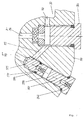
- a sealing lip is attached to the sealing insert Medium pressure on the surface of the cone and thereby seals.
- the medium therefore does not come up to that at all Screw.
- the advantage of this solution is the increased Reliability of sealing without the use of additional seals.
Landscapes
- Engineering & Computer Science (AREA)
- General Engineering & Computer Science (AREA)
- Physics & Mathematics (AREA)
- Fluid Mechanics (AREA)
- Mechanical Engineering (AREA)
- Control Of Fluid Pressure (AREA)
Applications Claiming Priority (6)
| Application Number | Priority Date | Filing Date | Title |
|---|---|---|---|
| SI9900185A SI20340A (sl) | 1999-07-22 | 1999-07-22 | Multifunkcijski aksialni regulacijski ventil |
| SI9900185 | 1999-07-23 | ||
| SI9900198A SI20341A (sl) | 1999-08-26 | 1999-08-26 | Aksialni regulacijski ventil |
| SI9900198 | 1999-08-30 | ||
| SI9900206A SI20387A (sl) | 1999-09-03 | 1999-09-03 | Aksialni regulacijski ventil |
| SI9900206 | 1999-09-06 |
Publications (2)
| Publication Number | Publication Date |
|---|---|
| EP1070889A2 true EP1070889A2 (fr) | 2001-01-24 |
| EP1070889A3 EP1070889A3 (fr) | 2002-07-24 |
Family
ID=27356155
Family Applications (1)
| Application Number | Title | Priority Date | Filing Date |
|---|---|---|---|
| EP00115784A Withdrawn EP1070889A3 (fr) | 1999-07-22 | 2000-07-21 | Soupape de contrôle axiale |
Country Status (1)
| Country | Link |
|---|---|
| EP (1) | EP1070889A3 (fr) |
Cited By (6)
| Publication number | Priority date | Publication date | Assignee | Title |
|---|---|---|---|---|
| CN101929575A (zh) * | 2010-09-19 | 2010-12-29 | 卓旦春 | 动态压差平衡阀 |
| CN108128634A (zh) * | 2018-01-29 | 2018-06-08 | 华北水利水电大学 | 一种可调脉冲旋流发生装置 |
| CN113389925A (zh) * | 2021-07-12 | 2021-09-14 | 蒋蒙亮 | 自闭阀 |
| CN114659698A (zh) * | 2022-03-06 | 2022-06-24 | 淮安市格洋浩瑞电子科技有限公司 | 一种抗冲击高稳定平膜型压力传感器 |
| CN114718767A (zh) * | 2022-03-31 | 2022-07-08 | 西安航天动力研究所 | 一种双路密封栓式喷注器装配测试方法 |
| CN119844578A (zh) * | 2024-12-30 | 2025-04-18 | 比亚迪股份有限公司 | 一种控制阀、热泵系统以及车辆 |
Family Cites Families (4)
| Publication number | Priority date | Publication date | Assignee | Title |
|---|---|---|---|---|
| FR1280679A (fr) * | 1960-11-22 | 1962-01-08 | Vanne | |
| FR1568846A (fr) * | 1967-12-28 | 1969-05-30 | ||
| FR2037292A1 (fr) * | 1969-03-31 | 1970-12-31 | Bryan Donkin Co Ltd | |
| US4431020A (en) * | 1981-10-08 | 1984-02-14 | Marotta Scientific Controls, Inc. | Flow-control system having a wide range of flow-rate control |
-
2000
- 2000-07-21 EP EP00115784A patent/EP1070889A3/fr not_active Withdrawn
Non-Patent Citations (1)
| Title |
|---|
| None |
Cited By (11)
| Publication number | Priority date | Publication date | Assignee | Title |
|---|---|---|---|---|
| CN101929575A (zh) * | 2010-09-19 | 2010-12-29 | 卓旦春 | 动态压差平衡阀 |
| CN101929575B (zh) * | 2010-09-19 | 2012-05-16 | 卓旦春 | 动态压差平衡阀 |
| CN108128634A (zh) * | 2018-01-29 | 2018-06-08 | 华北水利水电大学 | 一种可调脉冲旋流发生装置 |
| CN108128634B (zh) * | 2018-01-29 | 2023-11-24 | 华北水利水电大学 | 一种可调脉冲旋流发生装置 |
| CN113389925A (zh) * | 2021-07-12 | 2021-09-14 | 蒋蒙亮 | 自闭阀 |
| CN114659698A (zh) * | 2022-03-06 | 2022-06-24 | 淮安市格洋浩瑞电子科技有限公司 | 一种抗冲击高稳定平膜型压力传感器 |
| CN114659698B (zh) * | 2022-03-06 | 2024-04-09 | 淮安市格洋浩瑞电子科技有限公司 | 一种抗冲击高稳定平膜型压力传感器 |
| CN114718767A (zh) * | 2022-03-31 | 2022-07-08 | 西安航天动力研究所 | 一种双路密封栓式喷注器装配测试方法 |
| CN114718767B (zh) * | 2022-03-31 | 2023-06-23 | 西安航天动力研究所 | 一种双路密封栓式喷注器装配测试方法 |
| CN119844578A (zh) * | 2024-12-30 | 2025-04-18 | 比亚迪股份有限公司 | 一种控制阀、热泵系统以及车辆 |
| CN119844578B (zh) * | 2024-12-30 | 2026-02-10 | 比亚迪股份有限公司 | 一种控制阀、热泵系统以及车辆 |
Also Published As
| Publication number | Publication date |
|---|---|
| EP1070889A3 (fr) | 2002-07-24 |
Similar Documents
| Publication | Publication Date | Title |
|---|---|---|
| EP2271969B1 (fr) | Système de robinetterie permettant de réguler le débit ou la différence de pression | |
| DE102009011343B4 (de) | Durchflussmengenregler | |
| EP3008537B1 (fr) | Insert de compensation de pression | |
| EP1681520A2 (fr) | vanne pour de fluide | |
| DE102007026162A1 (de) | Absperrvorrichtung | |
| EP1070889A2 (fr) | Soupape de contrôle axiale | |
| EP2459912B1 (fr) | Contrôleur d'écoulement de gaz | |
| EP2644788B1 (fr) | Agencement de séparation de tuyaux | |
| DE102005052385B4 (de) | Druckminderer | |
| EP1903415B1 (fr) | Dispositif pour limiter le débit | |
| EP0943901B1 (fr) | Raccord pour un dispositif de mesure de débit d'un liquide | |
| DE202009015673U1 (de) | Druckmindereranordnung | |
| AT511599B1 (de) | Ventileinrichtung | |
| EP1239238A1 (fr) | Armature de raccordement pour radiateur | |
| DE4342164C2 (de) | Ventiloberteil für Armaturen mit einem Verlängerungsstück | |
| DE10132001C2 (de) | Thermostatischer Regler zur Regelung der Durchflussmenge eines Fluids | |
| DE4303483A1 (de) | Regler | |
| DE3235274C2 (de) | Sicherheitsvorrichtung für Stellgeräte, wie z.B. Druckminderer | |
| DE2904810C2 (de) | Drei- oder Mehrwegventil | |
| AT526972B1 (de) | Druckminderungsventil zur Volumenstromregelung | |
| DE19636410B4 (de) | Armatur für Wasserleitungen | |
| EP2644789B1 (fr) | Ensemble modulaire d'un agencement de séparation de tuyaux | |
| EP0527313B1 (fr) | Robinetterie pour conduits d'eau | |
| DE3347805C2 (de) | Vorrichtung zum Anpassen des Ansprechdruckes an die in der Abflußleitung gegebenen Druckverhältnisse bei einer Einrichtung zum Verhindern des Rückflusses eines Mediums aus einer Abflußleitung zurück in die Zuflußleitung | |
| DE10055614B4 (de) | Ventil,insbesondere Heizkörprventil |
Legal Events
| Date | Code | Title | Description |
|---|---|---|---|
| PUAI | Public reference made under article 153(3) epc to a published international application that has entered the european phase |
Free format text: ORIGINAL CODE: 0009012 |
|
| AK | Designated contracting states |
Kind code of ref document: A2 Designated state(s): AT BE CH CY DE DK ES FI FR GB GR IE IT LI LU MC NL PT SE |
|
| AX | Request for extension of the european patent |
Free format text: AL;LT;LV;MK;RO;SI |
|
| PUAL | Search report despatched |
Free format text: ORIGINAL CODE: 0009013 |
|
| AK | Designated contracting states |
Kind code of ref document: A3 Designated state(s): AT BE CH CY DE DK ES FI FR GB GR IE IT LI LU MC NL PT SE |
|
| AX | Request for extension of the european patent |
Free format text: AL;LT;LV;MK;RO;SI |
|
| 17P | Request for examination filed |
Effective date: 20020906 |
|
| AKX | Designation fees paid |
Designated state(s): AT BE CH CY DE DK ES FI FR GB GR IE IT LI LU MC NL PT SE |
|
| 17Q | First examination report despatched |
Effective date: 20040311 |
|
| STAA | Information on the status of an ep patent application or granted ep patent |
Free format text: STATUS: THE APPLICATION IS DEEMED TO BE WITHDRAWN |
|
| 18D | Application deemed to be withdrawn |
Effective date: 20040922 |