EP1070905A2 - Dispositif pour travailler à des canalisations - Google Patents
Dispositif pour travailler à des canalisations Download PDFInfo
- Publication number
- EP1070905A2 EP1070905A2 EP00115716A EP00115716A EP1070905A2 EP 1070905 A2 EP1070905 A2 EP 1070905A2 EP 00115716 A EP00115716 A EP 00115716A EP 00115716 A EP00115716 A EP 00115716A EP 1070905 A2 EP1070905 A2 EP 1070905A2
- Authority
- EP
- European Patent Office
- Prior art keywords
- tool
- carrier
- flexible sleeve
- carriage
- sleeve
- Prior art date
- Legal status (The legal status is an assumption and is not a legal conclusion. Google has not performed a legal analysis and makes no representation as to the accuracy of the status listed.)
- Granted
Links
- 239000000463 material Substances 0.000 claims description 5
- 239000000945 filler Substances 0.000 claims description 3
- 238000003801 milling Methods 0.000 claims description 3
- 238000007689 inspection Methods 0.000 description 2
- 230000007704 transition Effects 0.000 description 2
- 150000001875 compounds Chemical class 0.000 description 1
- 230000007547 defect Effects 0.000 description 1
- 230000002950 deficient Effects 0.000 description 1
- 238000006073 displacement reaction Methods 0.000 description 1
- 239000003651 drinking water Substances 0.000 description 1
- 235000020188 drinking water Nutrition 0.000 description 1
- 230000005684 electric field Effects 0.000 description 1
- 230000005672 electromagnetic field Effects 0.000 description 1
- 230000003628 erosive effect Effects 0.000 description 1
- 230000002349 favourable effect Effects 0.000 description 1
- 238000009415 formwork Methods 0.000 description 1
- 239000003673 groundwater Substances 0.000 description 1
- 239000002920 hazardous waste Substances 0.000 description 1
- 238000003780 insertion Methods 0.000 description 1
- 230000037431 insertion Effects 0.000 description 1
- 239000007788 liquid Substances 0.000 description 1
- 238000012423 maintenance Methods 0.000 description 1
- 239000004570 mortar (masonry) Substances 0.000 description 1
- 238000004382 potting Methods 0.000 description 1
- 230000036316 preload Effects 0.000 description 1
- 239000011241 protective layer Substances 0.000 description 1
- 238000007789 sealing Methods 0.000 description 1
- 239000010865 sewage Substances 0.000 description 1
- 239000007921 spray Substances 0.000 description 1
- 238000002604 ultrasonography Methods 0.000 description 1
- 239000002351 wastewater Substances 0.000 description 1
- XLYOFNOQVPJJNP-UHFFFAOYSA-N water Substances O XLYOFNOQVPJJNP-UHFFFAOYSA-N 0.000 description 1
Images


Classifications
-
- F—MECHANICAL ENGINEERING; LIGHTING; HEATING; WEAPONS; BLASTING
- F16—ENGINEERING ELEMENTS AND UNITS; GENERAL MEASURES FOR PRODUCING AND MAINTAINING EFFECTIVE FUNCTIONING OF MACHINES OR INSTALLATIONS; THERMAL INSULATION IN GENERAL
- F16L—PIPES; JOINTS OR FITTINGS FOR PIPES; SUPPORTS FOR PIPES, CABLES OR PROTECTIVE TUBING; MEANS FOR THERMAL INSULATION IN GENERAL
- F16L55/00—Devices or appurtenances for use in, or in connection with, pipes or pipe systems
- F16L55/26—Pigs or moles, i.e. devices movable in a pipe or conduit with or without self-contained propulsion means
- F16L55/265—Pigs or moles, i.e. devices movable in a pipe or conduit with or without self-contained propulsion means specially adapted for work at or near a junction between a main and a lateral pipe
-
- F—MECHANICAL ENGINEERING; LIGHTING; HEATING; WEAPONS; BLASTING
- F16—ENGINEERING ELEMENTS AND UNITS; GENERAL MEASURES FOR PRODUCING AND MAINTAINING EFFECTIVE FUNCTIONING OF MACHINES OR INSTALLATIONS; THERMAL INSULATION IN GENERAL
- F16L—PIPES; JOINTS OR FITTINGS FOR PIPES; SUPPORTS FOR PIPES, CABLES OR PROTECTIVE TUBING; MEANS FOR THERMAL INSULATION IN GENERAL
- F16L55/00—Devices or appurtenances for use in, or in connection with, pipes or pipe systems
- F16L55/26—Pigs or moles, i.e. devices movable in a pipe or conduit with or without self-contained propulsion means
- F16L55/28—Constructional aspects
Definitions
- the invention relates to a device for performing of sewer works according to the preamble of claim 1.
- Sewer pipes require maintenance and care as they especially at duct connections and duct branches often become defective. Mainly through signs of settlement or subsidence, cracks or major defects occur on; also corrosive or erosive components of the waste water cause damage. Through these damaged areas can produce hazardous waste water in uncontrolled large quantities seep into the ground and a great danger for that Represent groundwater and thus for drinking water. Moreover can deposits the hydraulic cross section narrow and to a closure and backwater of the sewage to lead. Therefore, damage can be determined as soon as possible and to fix.
- the required sewer work is special difficult for channels that are not accessible.
- the devices for inspection and Repair the canals are usually from operated by a service vehicle at a remote location and controlled and have a movable in a main channel Carriage on which an adjustable at least in one axis Device carrier is attached. It can vary depending Equipped with several translatory and rotary axes be provided.
- GB 2 147 682 A is a generic device known with a car and an equipment rack where various tools can be attached.
- the device is primarily used for connection and sealing a secondary channel at the connection to the main channel.
- the Tools can only travel a very short distance in the Penetrate secondary channel. Gripping pliers, a rotating cutting tool, an inflatable, elastic one Formwork element for pouring low-viscosity mortar or to put a partial inliner and a Spray device used to apply a protective layer become.
- DE 86 01 923 U1 is a device known for treating underground sewer pipes, which is a self-driving vehicle with a treatment tool owns.
- An articulated arm allows the tool to be in to move five degrees of freedom so that it is not just to the driven to be repaired, but also in the required Angular position can be brought.
- Through a Hose becomes liquid treatment material for the treatment tool fed.
- the coordination and control the drive devices can be manual or by computer control respectively.
- the condition of the channel wall can be with be watched by a television camera. Despite the five axes of movement the tool is only able to in the mouth area to act from secondary channels.
- DE 42 07 038 C2 shows a packer for Lining the transition area between a main channel and a confluent secondary channel.
- An expandable rubber jacket surrounds a support tube with which it is fixed at the ends connected is.
- the support tube has in the middle area an opening into which a rubber-coated or one-piece cylinder can.
- the packer is first aligned to the secondary channel. Then the sealed interior of the Carrier tube pressurized, causing the cylinder in the side channel and with the rubber jacket to the corresponding inner wall of the main channel or Sub-channel creates.
- insertion openings for a potting compound is provided, which through lines from the Front of the packer is fed from.
- the invention is based, sewer work to perform in places from the carriage of the device are distant, especially further away from the main channel in a side channel. This task is performed according to the Invention solved by the features of claim 1.
- the tool is flexible Sleeve connected to the equipment carrier.
- the flexible sleeve is carried on the equipment rack or on the cart and can be used with the Tool beyond the tool carrier by means of a conveyor promoted, e.g. in the form of powered Transport rollers.
- a conveyor promoted e.g. in the form of powered Transport rollers.
- the tool and / or a tool carrier connected to it are conveniently about supply and Control lines connected to a service vehicle that is connected to parked at a remote location outside the channel is. If the conditions are favorable, the control can also wirelessly by radio and energy supply by electrical Batteries or pressure accumulators take place. For space reasons the supply and control lines are advantageous housed in the flexible sleeve. This protects them against damage.
- the flexible sleeve on the outside Housing of the carriage and / or the equipment rack. in the the rest of it is stored in the main channel. That is why she is easily accessible and can be easily cleaned and serviced become.
- the equipment rack has the ability to insert the side channel a pivotable guide that the flexible sleeve on the Direction of the side channel.
- This leadership owns a guide channel that is funnel-shaped at its ends is expanded so that the flexible sleeve easily into the guide channel can break in.
- the swiveling guide or the equipment carrier point a centering device at its end facing the tool with a centering device on the tool or cooperates on the tool carrier.
- the tool or the tool carrier is in the final position held the guides, the flexible sleeve largely is relieved of lateral forces.
- the tool can Wagons can be safely transported through the main channel.
- the flexible sleeve is expediently a coil spring, which is driven by a threaded sleeve. In it is slightly pretensioned at the locking position of the tool, so that the contact to the Device carrier is not lost.
- the preload can be at switched off drive of the threaded sleeve are held, by the threaded sleeve being self-locking or is blocked by a locking mechanism, e.g. a locking magnet.
- the latch is useful loaded by a spring and is powered by an electromagnet unlocked, which is activated every time the Drive motor of the threaded sleeve is actuated.
- the bar magnet can be anywhere on the drive of the threaded sleeve attack. It expediently intervenes immediately the toothing of the gear of the threaded sleeve.
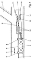
- a device according to the invention introduced, which has a carriage 3.
- a device carrier 4 is articulated via a parallel guide 5, with which a pivotable guide 10 for a flexible Sleeve 6 is connected.
- This is through a conveyor in the form of driven transport rollers 33, the are accommodated in the equipment rack 4, opposite the carriage 3 slidable.
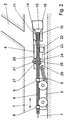
- the flexible sleeve 6 can be designed as a coil spring 32 be (Fig. 2) and at the end carries a tool 16, e.g. a tool carrier 29 with a milling cutter 18 (FIG. 5) Device 19 for pressing filler material with a material feed 30 (Fig. 4), or a packer 20 to set a partial inliner 21 (Fig. 3).
- a tool 16 e.g. a tool carrier 29 with a milling cutter 18 (FIG. 5)
- the coil spring 32 which is in the longitudinal direction on the carriage 3 is held by means of longitudinal guides 8 and 9, by a threaded sleeve 26 is moved longitudinally by the Threaded sleeve 26 with its internal thread in the threaded External contour of the coil spring 6 engages.
- the threaded sleeve 26 is rotatable by means of bearings 27, 28 in the housing of the Equipment carrier 4 is stored and is driven by a motor 22 a motor shaft 23, a pinion 24 and a seated thereon with the threaded sleeve 26 rotatably connected gear 25 driven.
- the motor 22 can be electric, pneumatic or be operated hydraulically.
- a locking magnet is used to block the threaded sleeve 26 31 provided in the toothing of the gear 25th intervenes.
- spur gear instead of the spur gear shown other tried and tested gear types can be used, e.g. Bevel gear or worm gear.
- the tool 16 is via supply and control lines 7 with a Service vehicle not shown outside the Main channel 1 connected.
- the supply and control lines 7 are laid within the coil spring 6 and thus largely protected against damage.
- the tool 16 In the transport position shown in FIGS. 1 and 2 the tool 16 is seated with a centering device 15 in a corresponding centering device 14 swiveling guide 10.
- the two centering devices 14 and 15 are pretensioned by the coil spring 32 pressed against each other (Fig. 2), so that the coil spring 32 during the transport of the tool 16 through the Car 3 is relieved of transverse forces. Furthermore, the tool 16 itself securely connected to trolley 3.
- a secondary channel 2 branches off from the main channel 1. Should the tool 16 can be moved into the secondary duct 2, first the carriage 3 and the equipment rack 4 in the main channel 1 set to secondary channel 2. You can do this Serve television cameras 17 on the device carrier 4 and / or on Tool carrier 29 or the tool 16, 19, 20 attached are. Instead of or in addition to the television cameras sensors can be provided, which according to different Working principles, e.g. with ultrasound, laser, radar, electromagnetic or electrical fields, etc. The TV cameras and sensors, as far as they with the Tool 16 are connected, later also for inspection the secondary channel 2 and for positioning the tool 16 serve.
- the guide 10 pivots in the direction of Secondary channel 2, so that when the longitudinal displacement of the flexible Sleeve 6 through the transport rollers 33 or the coil spring 32 through the threaded sleeve 26, the tool 16 in the secondary channel 2 is driven.
- the flexible sleeve 6 or the coil spring 32 is in a guide channel 11 of the pivotable guide 10 in the direction of the secondary channel 2 led.
- the guide channel 11 has at its ends funnel-shaped extensions 12 and 13 through which the flexible sleeve 6 or the coil spring 32 easily in the Guide channel 11 arrives.
- the tool according to the invention can 16 are driven very far into the secondary channel 2, i.e. over ten meters. There may be curvatures in the secondary duct Follow 2 and overcome constrictions. Reaches the tool 16 the place of use, it can through the flexible sleeve 6 or the coil spring 6 are secured in the longitudinal direction. If necessary, you can also use the tool holder 29 or on the tool 16 itself, not shown in detail Spreading devices are provided that the Support tool 16 on the walls of secondary duct 2.
Landscapes
- Engineering & Computer Science (AREA)
- General Engineering & Computer Science (AREA)
- Chemical & Material Sciences (AREA)
- Combustion & Propulsion (AREA)
- Mechanical Engineering (AREA)
- Sewage (AREA)
- Drilling And Boring (AREA)
- Specific Conveyance Elements (AREA)
- Electrical Discharge Machining, Electrochemical Machining, And Combined Machining (AREA)
- Sink And Installation For Waste Water (AREA)
Applications Claiming Priority (2)
| Application Number | Priority Date | Filing Date | Title |
|---|---|---|---|
| DE19934241A DE19934241A1 (de) | 1999-07-21 | 1999-07-21 | Vorrichtung zum Durchführen von Kanalarbeiten |
| DE19934241 | 1999-07-21 |
Publications (3)
| Publication Number | Publication Date |
|---|---|
| EP1070905A2 true EP1070905A2 (fr) | 2001-01-24 |
| EP1070905A3 EP1070905A3 (fr) | 2002-06-19 |
| EP1070905B1 EP1070905B1 (fr) | 2004-10-06 |
Family
ID=7915569
Family Applications (1)
| Application Number | Title | Priority Date | Filing Date |
|---|---|---|---|
| EP00115716A Expired - Lifetime EP1070905B1 (fr) | 1999-07-21 | 2000-07-21 | Dispositif pour travailler à des canalisations |
Country Status (3)
| Country | Link |
|---|---|
| EP (1) | EP1070905B1 (fr) |
| AT (1) | ATE278903T1 (fr) |
| DE (2) | DE19934241A1 (fr) |
Cited By (4)
| Publication number | Priority date | Publication date | Assignee | Title |
|---|---|---|---|---|
| WO2002099325A1 (fr) * | 2001-06-06 | 2002-12-12 | Commissariat A L'energie Atomique | Chariot porte-outil, notamment mobile dans une canalisation |
| WO2006087592A1 (fr) * | 2005-02-18 | 2006-08-24 | Inetec-Institute For Nuclear Technology D.O.O. | Assemblage d'arbre souple |
| WO2014207092A1 (fr) * | 2013-06-26 | 2014-12-31 | I.S.T. Innovative Sewer Technologies Gmbh | Procédé de rénovation de canalisations |
| CN118499618A (zh) * | 2024-07-18 | 2024-08-16 | 山西省交通新技术发展有限公司 | 一种传动结构及疏通管道的巡检机器人 |
Families Citing this family (10)
| Publication number | Priority date | Publication date | Assignee | Title |
|---|---|---|---|---|
| DE102004032356A1 (de) * | 2004-07-03 | 2006-02-09 | Tracto-Technik Gmbh | Kanalbearbeitungsgerät |
| DE102005023715A1 (de) * | 2005-05-19 | 2006-11-23 | Fraunhofer-Gesellschaft zur Förderung der angewandten Forschung e.V. | Vorrichtung und Verfahren zum Einbringen eines Kanals in bestehendes Mauerwerk |
| DE102007016823A1 (de) * | 2007-04-05 | 2008-11-06 | Tracto-Technik Gmbh & Co. Kg | Bohrsystem |
| DE102009031052A1 (de) * | 2009-06-30 | 2011-01-27 | Jt-Elektronik Gmbh | Verfahren und Vorrichtung zur Inspektion und gegebenenfalls Sanierung von in die Straßendecke mündenden Schächten |
| US9446455B2 (en) * | 2014-05-29 | 2016-09-20 | Sanexen Environmental Services Inc. | Drilling apparatus |
| MX2023011335A (es) | 2021-03-26 | 2023-10-19 | Ballard Marine Construction Llc | Sistemas de montaje de portadores, metodos y aparatos para reparacion de tuberias in situ. |
| DE102022106692A1 (de) * | 2022-03-22 | 2023-09-28 | Ibak Helmut Hunger Gmbh & Co Kg | Vorrichtung zur Kanalrohrinspektion und/oder -sanierung einer von einem Hauptkanal abzweigenden Anschlussleitung |
| DE102022003373B3 (de) * | 2022-09-13 | 2023-10-12 | Ibak Helmut Hunger Gmbh & Co Kg | Verfahren zum Sanieren eines Kanalrohrs mittels Schlauch-Relining |
| DE102023116834B3 (de) * | 2023-06-27 | 2023-12-07 | Ibak Helmut Hunger Gmbh & Co Kg | Vorrichtung für die Kanalrohrinspektion und/oder -sanierung einer von einem Hauptkanal abzweigenden Anschlussleitung |
| DE102023131982A1 (de) * | 2023-11-16 | 2025-05-22 | Ipek International Gmbh | Frässystem für Kanalsanierung |
Citations (3)
| Publication number | Priority date | Publication date | Assignee | Title |
|---|---|---|---|---|
| GB2147682A (en) | 1983-08-02 | 1985-05-15 | Water Res Centre | Robot device |
| DE8601923U1 (de) | 1986-01-25 | 1986-10-02 | Zawisla, Klaus, 6729 Hatzenbühl | Vorrichtung zur Behandlung unterirdisch verlegter Kanalrohre |
| DE4207038C2 (de) | 1992-03-06 | 1994-12-01 | Mueller Hans | Packer zum Auskleiden des Übergangsbereichs zwischen einem Awasserhauptrohr und einem einmündenden Hausanschlußrohr |
Family Cites Families (5)
| Publication number | Priority date | Publication date | Assignee | Title |
|---|---|---|---|---|
| DE3803274A1 (de) * | 1988-02-04 | 1989-08-17 | Mueller Umwelttechnik | Vorrichtung zur fernsehuntersuchung von rohrleitungen |
| DE4229787C2 (de) * | 1992-09-08 | 1994-10-20 | Jens Werner Kipp | Verfahren zur Untersuchung von von Hauptkanalrohren eines Kanalnetzes abzweigenden Nebenkanalrohren und Vorrichtung zur Durchführung des Verfahrens |
| DE4401758C1 (de) * | 1994-01-21 | 1995-05-24 | Wolfgang Rausch Gmbh & Co Kg | Selbstfahrendes Fahrzeug zur Fernsehinspektion, insbesondere der Abzweigleitungen von einem im Erdreich verlegten Sammelkanal aus |
| DE4417428C2 (de) * | 1994-05-18 | 2000-10-26 | Siemens Ag | Einrichtung zum Vorschub eines Prüf- oder Bearbeitungssystems in einer Rohrleitung |
| DE29700193U1 (de) * | 1996-01-10 | 1997-02-27 | JT Elektronik GmbH, 88131 Lindau | Vorschubantrieb mit Tender-Fahrwagen |
-
1999
- 1999-07-21 DE DE19934241A patent/DE19934241A1/de not_active Withdrawn
-
2000
- 2000-07-21 EP EP00115716A patent/EP1070905B1/fr not_active Expired - Lifetime
- 2000-07-21 DE DE50008067T patent/DE50008067D1/de not_active Expired - Lifetime
- 2000-07-21 AT AT00115716T patent/ATE278903T1/de not_active IP Right Cessation
Patent Citations (3)
| Publication number | Priority date | Publication date | Assignee | Title |
|---|---|---|---|---|
| GB2147682A (en) | 1983-08-02 | 1985-05-15 | Water Res Centre | Robot device |
| DE8601923U1 (de) | 1986-01-25 | 1986-10-02 | Zawisla, Klaus, 6729 Hatzenbühl | Vorrichtung zur Behandlung unterirdisch verlegter Kanalrohre |
| DE4207038C2 (de) | 1992-03-06 | 1994-12-01 | Mueller Hans | Packer zum Auskleiden des Übergangsbereichs zwischen einem Awasserhauptrohr und einem einmündenden Hausanschlußrohr |
Cited By (8)
| Publication number | Priority date | Publication date | Assignee | Title |
|---|---|---|---|---|
| WO2002099325A1 (fr) * | 2001-06-06 | 2002-12-12 | Commissariat A L'energie Atomique | Chariot porte-outil, notamment mobile dans une canalisation |
| FR2825655A1 (fr) * | 2001-06-06 | 2002-12-13 | Commissariat Energie Atomique | Chariot porte-outil, notamment mobile dans une canalisation |
| WO2006087592A1 (fr) * | 2005-02-18 | 2006-08-24 | Inetec-Institute For Nuclear Technology D.O.O. | Assemblage d'arbre souple |
| CN101115949B (zh) * | 2005-02-18 | 2012-05-23 | Inetec学院核工艺学有限公司 | 柔性轴组件 |
| HRP20050154B1 (hr) * | 2005-02-18 | 2019-02-22 | Inetec-Institut Za Nuklearnu Tehnologiju D.O.O. | Sklop fleksibilnog bužira |
| WO2014207092A1 (fr) * | 2013-06-26 | 2014-12-31 | I.S.T. Innovative Sewer Technologies Gmbh | Procédé de rénovation de canalisations |
| US10180205B2 (en) * | 2013-06-26 | 2019-01-15 | I.S.T. Innovative Sewer Technologies Gmbh | Sewer rehabilitation method |
| CN118499618A (zh) * | 2024-07-18 | 2024-08-16 | 山西省交通新技术发展有限公司 | 一种传动结构及疏通管道的巡检机器人 |
Also Published As
| Publication number | Publication date |
|---|---|
| EP1070905A3 (fr) | 2002-06-19 |
| ATE278903T1 (de) | 2004-10-15 |
| EP1070905B1 (fr) | 2004-10-06 |
| DE50008067D1 (de) | 2004-11-11 |
| DE19934241A1 (de) | 2001-02-08 |
Similar Documents
| Publication | Publication Date | Title |
|---|---|---|
| EP0158042B1 (fr) | Dispositif pour incorporer des tuyaux en matière plastique dans des égouts | |
| EP1070905B1 (fr) | Dispositif pour travailler à des canalisations | |
| EP0659270B1 (fr) | Procede et dispositif d'inspection aussi bien que de maintenance et de reparation de canaux secondaires qui derivent d'un egout principal | |
| EP0204694B1 (fr) | Dispositif pour effectuer des travaux d'amelioration sur une canalisation endommagee qui n'est plus accessible. | |
| EP3017885A1 (fr) | Dispositif de nettoyage de tuyaux | |
| EP0853211A1 (fr) | Robot et bras robotique pour la réparation de canalisations | |
| DE102013017374A1 (de) | "Vorrichtung zum Abschälen der äußerenSchicht(en) eines Rohres oder Kabels" | |
| DE2633173A1 (de) | Anordnung an einer kohlengewinnungseinrichtung | |
| EP3011220B1 (fr) | Système et procédé pour avancer un ensemble de tuyau | |
| DE102008027477B4 (de) | Vorrichtung zur Inspektion eines Kanals für Rohrleitungen und/oder Kabel | |
| DE102011083895A1 (de) | Vorrichtung und Verfahren zum Schweißen und Schweißteil | |
| DE102013010584B4 (de) | Kanalsanierungsverfahren und Kanalsanierungssystem | |
| DE10162477A1 (de) | Vorrichtung zur Reinigung eines Behälters für radioaktive Reststoffe | |
| DE202012009996U1 (de) | Vorrichtung zum Abschälen der äußeren Schicht(en) eines Rohres oder Kabels | |
| AT525867B1 (de) | Roboter zur grabenlosen Leitungs- und Schachtsanierung | |
| DE102016117163B4 (de) | Fahrzeug für eine Vorrichtung zum Abtragen kontaminierter Flächen und Verfahren zum Abtragen kontaminierter Flächen | |
| DE4240856C2 (de) | Tauchfähige Reinigungsvorrichtung | |
| EP0683347A2 (fr) | Dispositif pour la réparation de canalisations enterrées | |
| DE19511295A1 (de) | Vorrichtung zum Reparieren einer nicht begehbaren Rohrleitungs-Verzweigung oder Rohrleitungs-Einmündung | |
| DE102017128404B4 (de) | Vorrichtung und Verfahren zur Inspektion und/oder Sanierung einer unterirdischen Rohrleitung | |
| DE29619051U1 (de) | Fräsroboter | |
| AT405759B (de) | In einem rohrförmigen bauwerk verfahrbare vorrichtung zur bearbeitung und/oder inspektion der wände des rohrförmigen bauwerkes | |
| DE10117963A1 (de) | Gerät zum Einbringen eines Zugseiles in Leerrohre | |
| DE3590518C2 (fr) | ||
| DE3627556A1 (de) | Vorrichtung zur kanalsanierung |
Legal Events
| Date | Code | Title | Description |
|---|---|---|---|
| PUAI | Public reference made under article 153(3) epc to a published international application that has entered the european phase |
Free format text: ORIGINAL CODE: 0009012 |
|
| AK | Designated contracting states |
Kind code of ref document: A2 Designated state(s): AT BE CH CY DE DK ES FI FR GB GR IE IT LI LU MC NL PT SE |
|
| AX | Request for extension of the european patent |
Free format text: AL;LT;LV;MK;RO;SI |
|
| PUAL | Search report despatched |
Free format text: ORIGINAL CODE: 0009013 |
|
| AK | Designated contracting states |
Kind code of ref document: A3 Designated state(s): AT BE CH CY DE DK ES FI FR GB GR IE IT LI LU MC NL PT SE |
|
| AX | Request for extension of the european patent |
Free format text: AL;LT;LV;MK;RO;SI |
|
| 17P | Request for examination filed |
Effective date: 20021219 |
|
| AKX | Designation fees paid |
Designated state(s): AT BE CH CY DE DK ES FI FR GB GR IE IT LI LU MC NL PT SE |
|
| 17Q | First examination report despatched |
Effective date: 20030527 |
|
| GRAP | Despatch of communication of intention to grant a patent |
Free format text: ORIGINAL CODE: EPIDOSNIGR1 |
|
| GRAS | Grant fee paid |
Free format text: ORIGINAL CODE: EPIDOSNIGR3 |
|
| GRAA | (expected) grant |
Free format text: ORIGINAL CODE: 0009210 |
|
| AK | Designated contracting states |
Kind code of ref document: B1 Designated state(s): AT BE CH CY DE DK ES FI FR GB GR IE IT LI LU MC NL PT SE |
|
| PG25 | Lapsed in a contracting state [announced via postgrant information from national office to epo] |
Ref country code: IT Free format text: LAPSE BECAUSE OF FAILURE TO SUBMIT A TRANSLATION OF THE DESCRIPTION OR TO PAY THE FEE WITHIN THE PRESCRIBED TIME-LIMIT;WARNING: LAPSES OF ITALIAN PATENTS WITH EFFECTIVE DATE BEFORE 2007 MAY HAVE OCCURRED AT ANY TIME BEFORE 2007. THE CORRECT EFFECTIVE DATE MAY BE DIFFERENT FROM THE ONE RECORDED. Effective date: 20041006 Ref country code: NL Free format text: LAPSE BECAUSE OF FAILURE TO SUBMIT A TRANSLATION OF THE DESCRIPTION OR TO PAY THE FEE WITHIN THE PRESCRIBED TIME-LIMIT Effective date: 20041006 Ref country code: FR Free format text: LAPSE BECAUSE OF NON-PAYMENT OF DUE FEES Effective date: 20041006 Ref country code: FI Free format text: LAPSE BECAUSE OF FAILURE TO SUBMIT A TRANSLATION OF THE DESCRIPTION OR TO PAY THE FEE WITHIN THE PRESCRIBED TIME-LIMIT Effective date: 20041006 Ref country code: GB Free format text: LAPSE BECAUSE OF FAILURE TO SUBMIT A TRANSLATION OF THE DESCRIPTION OR TO PAY THE FEE WITHIN THE PRESCRIBED TIME-LIMIT Effective date: 20041006 Ref country code: IE Free format text: LAPSE BECAUSE OF FAILURE TO SUBMIT A TRANSLATION OF THE DESCRIPTION OR TO PAY THE FEE WITHIN THE PRESCRIBED TIME-LIMIT Effective date: 20041006 |
|
| REG | Reference to a national code |
Ref country code: GB Ref legal event code: FG4D Free format text: NOT ENGLISH |
|
| REG | Reference to a national code |
Ref country code: CH Ref legal event code: EP |
|
| REG | Reference to a national code |
Ref country code: IE Ref legal event code: FG4D Free format text: GERMAN |
|
| REF | Corresponds to: |
Ref document number: 50008067 Country of ref document: DE Date of ref document: 20041111 Kind code of ref document: P |
|
| PG25 | Lapsed in a contracting state [announced via postgrant information from national office to epo] |
Ref country code: GR Free format text: LAPSE BECAUSE OF FAILURE TO SUBMIT A TRANSLATION OF THE DESCRIPTION OR TO PAY THE FEE WITHIN THE PRESCRIBED TIME-LIMIT Effective date: 20050106 Ref country code: SE Free format text: LAPSE BECAUSE OF FAILURE TO SUBMIT A TRANSLATION OF THE DESCRIPTION OR TO PAY THE FEE WITHIN THE PRESCRIBED TIME-LIMIT Effective date: 20050106 Ref country code: DK Free format text: LAPSE BECAUSE OF FAILURE TO SUBMIT A TRANSLATION OF THE DESCRIPTION OR TO PAY THE FEE WITHIN THE PRESCRIBED TIME-LIMIT Effective date: 20050106 |
|
| PG25 | Lapsed in a contracting state [announced via postgrant information from national office to epo] |
Ref country code: ES Free format text: LAPSE BECAUSE OF FAILURE TO SUBMIT A TRANSLATION OF THE DESCRIPTION OR TO PAY THE FEE WITHIN THE PRESCRIBED TIME-LIMIT Effective date: 20050117 |
|
| NLV1 | Nl: lapsed or annulled due to failure to fulfill the requirements of art. 29p and 29m of the patents act | ||
| GBV | Gb: ep patent (uk) treated as always having been void in accordance with gb section 77(7)/1977 [no translation filed] |
Effective date: 20041006 |
|
| REG | Reference to a national code |
Ref country code: IE Ref legal event code: FD4D |
|
| PG25 | Lapsed in a contracting state [announced via postgrant information from national office to epo] |
Ref country code: AT Free format text: LAPSE BECAUSE OF NON-PAYMENT OF DUE FEES Effective date: 20050721 Ref country code: LU Free format text: LAPSE BECAUSE OF NON-PAYMENT OF DUE FEES Effective date: 20050721 Ref country code: CY Free format text: LAPSE BECAUSE OF FAILURE TO SUBMIT A TRANSLATION OF THE DESCRIPTION OR TO PAY THE FEE WITHIN THE PRESCRIBED TIME-LIMIT Effective date: 20050721 |
|
| PG25 | Lapsed in a contracting state [announced via postgrant information from national office to epo] |
Ref country code: LI Free format text: LAPSE BECAUSE OF NON-PAYMENT OF DUE FEES Effective date: 20050731 Ref country code: MC Free format text: LAPSE BECAUSE OF NON-PAYMENT OF DUE FEES Effective date: 20050731 Ref country code: BE Free format text: LAPSE BECAUSE OF NON-PAYMENT OF DUE FEES Effective date: 20050731 Ref country code: CH Free format text: LAPSE BECAUSE OF NON-PAYMENT OF DUE FEES Effective date: 20050731 |
|
| PLBE | No opposition filed within time limit |
Free format text: ORIGINAL CODE: 0009261 |
|
| STAA | Information on the status of an ep patent application or granted ep patent |
Free format text: STATUS: NO OPPOSITION FILED WITHIN TIME LIMIT |
|
| 26N | No opposition filed |
Effective date: 20050707 |
|
| EN | Fr: translation not filed | ||
| REG | Reference to a national code |
Ref country code: CH Ref legal event code: PL |
|
| BERE | Be: lapsed |
Owner name: *EST EINLAUFSANIERUNGSTECHNIK G.M.B.H. Effective date: 20050731 Owner name: *KANALTECHNIK GEIGER& KUNZ G.M.B.H. & CO. K.G. Effective date: 20050731 |
|
| PG25 | Lapsed in a contracting state [announced via postgrant information from national office to epo] |
Ref country code: PT Free format text: LAPSE BECAUSE OF NON-PAYMENT OF DUE FEES Effective date: 20050306 |
|
| PG25 | Lapsed in a contracting state [announced via postgrant information from national office to epo] |
Ref country code: DE Free format text: LAPSE BECAUSE OF NON-PAYMENT OF DUE FEES Effective date: 20080201 |
|
| PGRI | Patent reinstated in contracting state [announced from national office to epo] |
Ref country code: DE Effective date: 20080708 |
|
| PGFP | Annual fee paid to national office [announced via postgrant information from national office to epo] |
Ref country code: DE Payment date: 20130729 Year of fee payment: 14 |
|
| REG | Reference to a national code |
Ref country code: DE Ref legal event code: R119 Ref document number: 50008067 Country of ref document: DE |
|
| PG25 | Lapsed in a contracting state [announced via postgrant information from national office to epo] |
Ref country code: DE Free format text: LAPSE BECAUSE OF NON-PAYMENT OF DUE FEES Effective date: 20150203 |
|
| REG | Reference to a national code |
Ref country code: DE Ref legal event code: R119 Ref document number: 50008067 Country of ref document: DE Effective date: 20150203 |