EP1070921A2 - Heizkörper mit mittigem Anschluss - Google Patents
Heizkörper mit mittigem Anschluss Download PDFInfo
- Publication number
- EP1070921A2 EP1070921A2 EP00103430A EP00103430A EP1070921A2 EP 1070921 A2 EP1070921 A2 EP 1070921A2 EP 00103430 A EP00103430 A EP 00103430A EP 00103430 A EP00103430 A EP 00103430A EP 1070921 A2 EP1070921 A2 EP 1070921A2
- Authority
- EP
- European Patent Office
- Prior art keywords
- heat exchanger
- type
- heating device
- heating
- valve
- Prior art date
- Legal status (The legal status is an assumption and is not a legal conclusion. Google has not performed a legal analysis and makes no representation as to the accuracy of the status listed.)
- Withdrawn
Links
Images



Classifications
-
- F—MECHANICAL ENGINEERING; LIGHTING; HEATING; WEAPONS; BLASTING
- F24—HEATING; RANGES; VENTILATING
- F24D—DOMESTIC- OR SPACE-HEATING SYSTEMS, e.g. CENTRAL HEATING SYSTEMS; DOMESTIC HOT-WATER SUPPLY SYSTEMS; ELEMENTS OR COMPONENTS THEREFOR
- F24D19/00—Details
- F24D19/0002—Means for connecting central heating radiators to circulation pipes
-
- F—MECHANICAL ENGINEERING; LIGHTING; HEATING; WEAPONS; BLASTING
- F24—HEATING; RANGES; VENTILATING
- F24D—DOMESTIC- OR SPACE-HEATING SYSTEMS, e.g. CENTRAL HEATING SYSTEMS; DOMESTIC HOT-WATER SUPPLY SYSTEMS; ELEMENTS OR COMPONENTS THEREFOR
- F24D19/00—Details
- F24D19/0002—Means for connecting central heating radiators to circulation pipes
- F24D19/0017—Connections between supply and inlet or outlet of central heating radiators
- F24D19/0021—Flexible tubes or hoses
-
- F—MECHANICAL ENGINEERING; LIGHTING; HEATING; WEAPONS; BLASTING
- F24—HEATING; RANGES; VENTILATING
- F24D—DOMESTIC- OR SPACE-HEATING SYSTEMS, e.g. CENTRAL HEATING SYSTEMS; DOMESTIC HOT-WATER SUPPLY SYSTEMS; ELEMENTS OR COMPONENTS THEREFOR
- F24D19/00—Details
- F24D19/0002—Means for connecting central heating radiators to circulation pipes
- F24D19/0026—Places of the inlet on the radiator
- F24D19/0029—Places of the inlet on the radiator on a top corner
-
- F—MECHANICAL ENGINEERING; LIGHTING; HEATING; WEAPONS; BLASTING
- F24—HEATING; RANGES; VENTILATING
- F24D—DOMESTIC- OR SPACE-HEATING SYSTEMS, e.g. CENTRAL HEATING SYSTEMS; DOMESTIC HOT-WATER SUPPLY SYSTEMS; ELEMENTS OR COMPONENTS THEREFOR
- F24D19/00—Details
- F24D19/0002—Means for connecting central heating radiators to circulation pipes
- F24D19/0039—Places of the outlet on the radiator
- F24D19/0051—Places of the outlet on the radiator on the bottom on the opposite corner
-
- F—MECHANICAL ENGINEERING; LIGHTING; HEATING; WEAPONS; BLASTING
- F24—HEATING; RANGES; VENTILATING
- F24D—DOMESTIC- OR SPACE-HEATING SYSTEMS, e.g. CENTRAL HEATING SYSTEMS; DOMESTIC HOT-WATER SUPPLY SYSTEMS; ELEMENTS OR COMPONENTS THEREFOR
- F24D19/00—Details
- F24D19/0002—Means for connecting central heating radiators to circulation pipes
- F24D19/0039—Places of the outlet on the radiator
- F24D19/0053—Places of the outlet on the radiator on the bottom on the same side
-
- F—MECHANICAL ENGINEERING; LIGHTING; HEATING; WEAPONS; BLASTING
- F24—HEATING; RANGES; VENTILATING
- F24D—DOMESTIC- OR SPACE-HEATING SYSTEMS, e.g. CENTRAL HEATING SYSTEMS; DOMESTIC HOT-WATER SUPPLY SYSTEMS; ELEMENTS OR COMPONENTS THEREFOR
- F24D19/00—Details
- F24D19/0002—Means for connecting central heating radiators to circulation pipes
- F24D19/0056—Supplies from the central heating system
- F24D19/0058—Supplies from the central heating system coming out the floor
- F24D19/0063—Supplies from the central heating system coming out the floor under the radiator
Definitions
- the invention relates to a heating device, in particular for central and / or District heating systems according to claim 1.
- the invention is also directed to a convector register heater according to claim 10.
- radiators have a single type of radiator, for example a convector or a radiant heater. Both types of Radiators have certain advantages, but they are paired together can be.
- the designated task is at least predominantly performed by a heating device solved with the features listed in claim 1. Furthermore, said Task also at least predominantly by a heater according to the Claim 10 solved.
- connection sections can be provided which are designed for central connection or for lateral connection to the central and / or district heating systems.
- Such connecting sections can be formed, for example, from plastic pipe, plastic-metal-plastic composite pipe or the like.
- the heat exchanger of the second type can advantageously be divided into two sections be connected via a line section, or can partially the ribs on the pipe register have been left out, so that the line section results, wherein the supply and return connections are arranged on the line section are.
- the second heat exchanger for example the tube register with fins, can advantageously at least in the area of the supply or return connections have a collecting section. So here it is possible to have a variety connecting pipes of a pipe register via the collecting sections, to only the manifold section to the forward or return and / or to a subsequent radiator of another connected in parallel or in series Type, for example a panel radiator to connect.
- a valve device is advantageously arranged in the area of the radiator-side supply or return connections or in the area of the connecting lines under the heat exchangers of the two types on the supply or return side.
- the flow of the heating medium in the course of the heat exchanger of the second type or in the course of the heat exchanger of the first type or in between can be regulated or brought to a standstill in order to adjust the heating power of the heating device according to the invention.
- a thermostat device or a thermostatic head is arranged in the area of the radiator-side supply and return connections, in particular on the lower, central section of the heating device or of the second type of heat exchanger, which is preferably arranged in the lower area of the heating device or beyond a particularly lower cladding of the heating device is.
- thermostat device has the effect that falsification of the reaction of the thermostat device by radiant heat or convection heat of the heating device itself is reduced as far as possible, since little heat is released in this area.
- thermostat device it is also possible to provide the thermostat device elsewhere, for example in a conventional manner on an upper, lateral area of the radiator or elsewhere.
- the second type of heat exchanger it is also possible for the second type of heat exchanger to be above the first type of heat exchanger to arrange, but it has proven to be particularly advantageous if the second type of heat exchanger with the pipe registers in the lower area of the Radiator or the heating device according to the invention is provided.
- the activating effect of the predominantly convective heat exchanger second type come into their own.
- the heat exchanger of the second type there can advantageously be collecting sections be provided to collect the heating medium from the pipe registers or to distribute in these and forward them to the return of the heating device or to receive from the flow of the heating device.
- the heating medium can also initially in the plate heater of the invention Heater are initiated and at the end of the panel radiator via a Header section in the pipe register of the heat exchanger of the second type be initiated.
- radiator-side central flow connection via a valve adapter or a connection fitting to the first type of heat exchanger, in particular one heating plate or several heating plates connected is and the heat transfer medium after the first type of heat exchanger flows onto the second heat exchanger type, preferably in the region of at least one header line section, and that the radiator-side, central return connection the second type of heat exchanger is connected.
- an assembly device preferably on the radiator-side supply and return connection a plate, arranged the corresponding holes for screws or the like having.
- This mounting device can be connected to a console, for example become.
- adjacent pipe sections are above manifold sections connected.
- the pipe sections can be paired with one connected to these pairs of manifold sections or it can header sections on either side of the supply and return connections be provided to which several or all of the tubes on one side of the second Heat exchanger types are connected.
- Both the first type of heat exchanger and the second type of heat exchanger can a valve or a thermostatic valve can be assigned.
- the two types of heat exchanger must be connected in parallel to the flow or return be connected so that an independent control of the heating medium the different heat exchanger types is possible.
- the first type of heat exchanger Practically used for heating periods that have a low to medium Require heating power and the second type of heat exchanger can be activated, if this requires colder or especially cold weather.
- the heating device according to the invention can be at least approximately in the middle of the upper region of the heating device or the heat exchanger of the first type, preferably an essentially radiant heat emitting heat exchanger, a valve device can be arranged.
- a valve device can be arranged starting from the flow of the heating device according to the invention, in particular the heating medium to the central valve via a flexible line, preferably a corner valve.
- a thermostat or thermostat control element may be provided in the center. This can protrude from an upper covering of the heating device according to the invention and can in particular be retractable.
- the central valve in particular a corner valve, can be connected to a supply fitting of the heat exchanger of the first type.
- the flow fitting nozzle can be blind-closed on the valve side.
- the provided thermostat device can preferably be connected to a capillary provided temperature sensor be connected.
- This temperature sensor should preferably be arranged so that it detects the room air temperature. there it can be arranged laterally on or next to the heating device.
- the heat exchanger of the second type which is preferably used as a convection heater, can be arranged is formed on one side with its flow to the return of the radiator of the first type.
- the radiator of the second type on the side connected to the radiator of the first type, the opposite the flow connection of the radiator of the first type.
- the heat exchanger of the first type should be centered on the flow from the central heating be connected to the side while the heat exchanger of the second type the heat exchanger of the first type is connected, it may be necessary that the heat exchanger of the first type is provided with a throttle device which Flow resistance through the heat exchanger of the first type, which is otherwise asymmetrical would be symmetrized in order to achieve an even flow and thus to achieve heat dissipation from the heat exchanger of the first type.
- valve device and the thermostat device are in the middle of the top of the heat exchanger provided of the first type, it is preferred if the mechanical connection the thermostat device to the valve device a rotary movement in can implement a linear movement.
- An axis of rotation can preferably be used run perpendicular to the linear axis, the linear axis of the movement of a plunger corresponds to the valve device which moves the valve disk.
- a device can preferably be used as the remote sensor possible influence of the possibly very close heating device at least partially is able to compensate.
- a remote sensor can be used here, for example, which consists of components with different expansion coefficients, or from a material that has a non-linear characteristic in a predetermined range which at least partially increases the influence of the heating device can compensate.
- the advantages are also based on a heating device with a Pipe or pipe register with a flow and return connection and on the register provided convection ribs, the forward and the return connection are arranged centrally on the pipe register.
- a central connection is also on here a central heating system or district heating system possible without any problems.
- the tube register can advantageously center a convection rib-free center Have area in which the flow and return connections are arranged. Because of the resulting free space makes it possible to place a valve or to create a thermostatic valve, a mounting device and the like.
- radiators according to the invention With pipe register To be able to, it is advantageous if this in this area by means of manifolds be summarized.
- This area between the manifolds is also suitable especially to arrange a valve device that regulates the flow of a heating medium, in particular from one radiator section to another radiator section of the pipe register.
- a thermostatic head can advantageously be used be provided, which is arranged in particular at the lower end of the radiator or protrudes from this.
- the thermostatic head or the thermostatic device largely free from adulteration due to the heat given off by the heating device itself hold.
- the valve of the heating device is advantageously according to the second aspect of the present To achieve or adjust the invention via an adjusting button on the upper Area or an upper cover protrudes from the center of the radiator, or from a front or front panel protrudes. In the latter case, it is advantageous to provide a deflection mechanism, the movement of the control knob on the valve transmits.
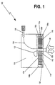
- the heater 100 has a first heat exchanger 112 of a first type, which is specified as a convector register 112. Another heat exchanger 110 is provided, which is specified here as a plate heater.
- the convector register 112 has two sections 114, 116, between which ribs 131 which are otherwise present are not provided.
- the convector register 112 is traversed by heating pipes 130a, 130b, 130c, the one Lead heat transfer medium that through a radiator flow 130 into the heating device 100 is initiated. From these heating tubes 130a, 130b, 130c, the heat of the Heat transfer medium on the heating fins 131.
- the heating fins as well as the pipes can be made of sheet metal or sheet steel, copper, brass or other usual materials.
- the heating medium flows from the radiator flow 130 via a connecting line 124 to a valve connection set 126 and from there, regulated via the valve provided here, into the heating plate 110.
- the connecting line 124 can advantageously consist of a Be made of plastic material.
- a metal tube can also be used here, however, metal pipes are less adaptable and require more effort to adapt such metal pipes to existing on-site connections. Be against it Plastic lines, in particular also plastic-metal-plastic composite pipes as connecting lines 124 used, tedious classic plumbing activities are eliminated.
- the heat transfer medium flows over an existing one Register the heating plate 110 to the lower area of the heating plate to pass from there a connection fitting 120 to flow into a manifold 118b from which the heating medium can flow into the tubes 130c, 130b, 130a of the convector register.
- a connection fitting 120 to flow into a manifold 118b from which the heating medium can flow into the tubes 130c, 130b, 130a of the convector register.
- Heat transfer medium has flowed through the convector register 112, it will be in the manifold 118a summarized, then preferably via a further connecting line 122 made of plastic or the like, to the return 128 of the heating device 100 reach.
- the heating device 100 thus provides the advantage that, on the one hand, a certain heating characteristic can be generated by connecting two types of heat exchangers 110, 112, the production being simplified by the combination of the features of this embodiment according to the first aspect of the present invention contributes to simplified assembly.
- the central connection method in connection with the convector register, which is divided into two sections, whereby an un-ribbed area is provided, and the heating plate, which are connected to one another partly via plastic lines and partly via connection fittings.
- valves also on the lower area of the radiator can be provided and that the flow 130 of the heating device 100 initially the heat transfer medium can supply the convector register 112. From this embodiment would still be very beneficial, though not with all the benefits of the maximum intensity, like the embodiment shown in FIG. 1.
- FIG. 2 shows a further heating device with features according to a second aspect of the present invention.
- a convector can be connected be provided with a heating plate, as shown in FIG. 1.
- FIG. 2 accordingly shows a heating device 200 with a convector register 214, 216, which is divided into two sections, each on the right and left of a central connector are provided.
- the connection does not necessarily have to be exactly in the middle be provided, even if this is preferred.
- Both the left section 214 and The right section 216 of the heating device 200 also has tubes 230a, 230b the heating fins 231 are attached.
- the heating fins 231 can be welded, soldered or just be plugged on.
- the heating fins 231 are used in accordance with the usual mode of operation of a convector, the heat-emitting surface of the heating pipes 230a, 230b is essential to enlarge and as convection channels for rising air to be heated serve.
- a schematic top view of the heating device 200 is shown, see above that a front cover 232 is provided with an opening through which a valve portion 236 protrudes, which preferably the thermostatic head of the thermostatic valve 236, 224th having.
- the deflection mechanism located in the valve section 224 can be used Valve plate opposite the valve seat (not shown) are moved or controlled.
- the valve 224 and 236 acts on the flow of the heating medium in the valve or Connection line section 222 a.
- the heat transfer medium is connected via manifolds 226a, 228a summarized and through the line 222 in its flow through the valve 224, 236 passed through in a controlled manner.
- the line sections 228, 230 can be made of plastic, equally like the lines 122, 124 of the heater 100 according to the first aspect of the present invention.
- FIG. 2a it can be seen that the manifolds 226a heating pipes 230a, 230b of the Connect the pipe register of the convector heater of the heating device 200 horizontally or summarize to a flow of the heat transfer medium through the radiator produce.
- a vertical arrangement of manifolds can also be used, but not heating pipes lying next to each other but connected one below the other become.
- the return of the heating plate must then be behind the section 216 of the convector can be provided.
- the tubes 230a, 230b are each horizontally combined in pairs.
- two or three heating pipes 130a, 130b, 130c can be combined via vertical manifolds 118. That means it can any arrangements of manifolds and heating pipes can be provided without the Thoughts according to the present invention according to one of the aspects described leave.
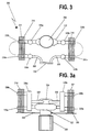
- FIG. 3 shows the configuration of the convector sections according to FIG. 3 from a different perspective.
- a valve 336, 322 is provided, which is not designed as a valve with a deflection mechanism, but in which the valve tappet or the control rod of the valve originating from a thermostat cartridge in the conventional Acting directly and without an angle deflection mechanism on the valve plate. Also here the valve 336 looks out of the front cover 332. Of course, the control knob could 336 of valve 336, 322 also look out of an upper cover plate. In both The influence of the thermostatic cartridge of the valve is not decisive in these cases, since the Heating power of the heater 300 in the area between the sections 314, 316 is not particularly essential.
- the essence of the radiator according to the present invention or of the heat exchanger type 112 or 314, 316, 214, 216 are defined such that heating fins are omitted in the central area or so that instead of the otherwise
- a central connection is provided in the central area of the fins to be provided, in the area of which a valve is additionally provided, with manifold sections 326a, 328a summarize the heat transfer medium and through a pipe section in the Direction of action of the valve to the flow of heat transfer medium through the Control heater 300 in total.
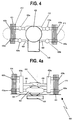
- the embodiment of a heater 400 according to the second aspect of FIG. The present invention is designed in the same way as the heating devices according to 2 to 3a, but the arrangement of the central valve is different.
- the thermostatic head 436 is arranged to be on the lower portion of the heater 400 looks out. In this way, the thermostatic head 436 of a passing cool airflow that is the actual temperature of the room air reflects, influences.
- An adjustment button 425 is provided, which has an openwork Front comparison 432 may be accessible.
- This valve also has a deflection mechanism on so that an adjustment of the Flow of the heat transfer medium can be made through the valve.
- the adjustment distance between the valve plate and a bevel gear the thermostatic head can be changed to a non-thermostatic, manual control perform.
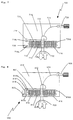
- FIG. 5 in conjunction with FIG. 6 shows basic circuit variants in the case of an odd one Number of horizontal, superimposed rows of pipes.
- an embodiment 500 according to the present invention has a continuous one Heating coil 530d, which of course will usually be present several times, in order to be able to transfer enough heating power to slats 531, which are connected to the heating coil 530d are connected.
- the heating coil 530d is on the respective manifolds 518c at the supply and return of the heating coil or the heating coils 530d connected.
- heating medium flowing into the radiator is first introduced into the heating plate 510 and then through a hot plate return port 520 into the flow side manifold 518c to be distributed from there to the plurality of heating coils 530d.
- the heating medium initially flows in the return of the heating coil or heating coils 530d into the return pipe 518c and from there into a connection fitting 519, to which the return line 522 is attached, so that the heating medium from here to the heating system-side return and thus can reach the connection section 528.
- the embodiment 600 according to FIG. 6 has a similar design, only that here, in contrast to the embodiment 500 according to FIG. 5, the convector 612 according to the counterflow principle is coupled to the heating plate. This type of arrangement or flow the heating plate 610 and the convector 612 guarantees maximum heating output.
- a connection section extends from the hotplate-side return connection 620 619, to which the feed pipe 618c is connected, via which a plurality of coils 630d can be supplied with the heating medium.
- the relevant coils 630d are again connected through a return-side manifold 318c summarized and via a connection section 619 in the connection line 622 transferred from where the heating medium to the return to the central heating system to be led.
- 7 and 8 represent basic circuit variants with an even number of horizontal, overlying rows of pipes.
- the embodiment 700 according to FIG. 7 corresponds in principle to the embodiment 500 according to FIG. 5.
- the heating coil comprises three bends and four straight sections, which are connected to the heating fins 731, i.e. it is a straight pipe section
- the coil 730d There is more in the coil 730d than in the coil 530d according to Figure 5.
- This configuration of the convector 712 requires that the lead and the Return connection of the convector are arranged on the same side.
- FIG. 9 shows a central connection section of a radiator according to FIG. 1 or 5 to 8, or according to Figures 2 to 4a.
- a convection preventing section 960 is U-shaped, the U-shape can also be used upside down, as can be seen in FIG. 9.
- the U-shape is not important but only that it can be prevented that in the area of the center connection Air rise without significant heating in the lamella-free area can.
- section 960 has side legs 962a, 962b and a base section 960, which is provided with openings 964 through which the connecting lines to Panel radiators and can be passed through the convector.
- Openings are also provided for the pipes 930 of the convector, specifically in the lateral ones Thighs 962a, 962b.
- FIG. 10 another embodiment 1000 is presented, which can in principle be of any design, that is to say, according to any of the embodiments according to one of FIGS. 1 to 8 or 9, in addition to the side ends of the convector within a radiator or the radiator cover Blocking sections 1064 'are provided which, according to the principle of the flow blocking section 960, prevent air flows from flowing sideways past the convector, the two sections 1014, 1016 of which can be partially recognized, without substantial heating.
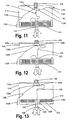
- FIG. 11 is another embodiment of a heater 1110 with features according to the invention.
- the heat exchanger of the second type the is called the convector 1112
- the connection of the heating device 1110 as a whole designed or implemented, such as in the heater 100 according to Fig. 1. Only different components are discussed here.
- a valve in particular a corner valve 1126g, is at the upper central area of the heating device 1110 is provided and is via a flexible feed line 1124, preferably a Plastic hose, connected to the flow from the central heating.
- the valve 1126g is via a connecting piece 1126d and another flexible or also rigid Line 1126c connected to the socket of a common flow set 1126b.
- a valve connector portion 1126a of the lead assembly 1126b is blind flanged as one additional valve is not required here.
- the valve 1126g is controlled via a thermostat line 1126, which can protrude from the upper cover of the heating device 1110 at the upper end.
- the thermostatic head 1126 can be equipped with a retractable operating attachment, for example based on a ballpoint pen with a locking mechanism with a control cam.
- the thermostatic head and the valve 1126g can be connected to one another in a conventional manner for control purposes.
- the thermostatic head 1126 can be connected via a capillary line 1126e with a remote temperature sensor 1126f to be connected to one of the heat of the heater 1110 itself to be able to record the most uninfluenced room temperature.
- the heating device 1210 according to FIG. 12 is also with regard to a convector 1212 formed according to the embodiment of FIG. 1, that is in principle according to the convector 1112 according to FIG. 11.
- Deviating from the embodiment according to FIG. 11, the embodiment according to FIG. 12 the flow from the central heating via a preferably flexible connection hose 1224 to a central connection 1226b at the approximately central upper end of the heating device Tied in 1210.
- a valve 1226a regulates the inflow of the heating medium the flow 1226b in the heat exchanger of the first type.
- the valve 1226g is over a Deflection mechanism adjusted or thermostatically controlled from a thermostat head 1226.
- the adjustment mechanism which is an adjusting movement on the thermostat or thermostatic head 1226 to a movement of a valve plate of the valve 1226g, thereby realizes that a rotary movement of the thermostat in a linearized movement is implemented, which moves the valve tappet and thus the valve plate.
- the thermostat head 1226 receives information about the actual room temperature supplied via a remote sensor 1226f.
- the embodiment according to FIG. 13 is the first with regard to the heat exchanger Type, that is, the radiant heat emitting heat exchanger, which is principally central Connection to a central heating system and the central flow to the heat exchanger of the first type and the central arrangement of the thermostat 1126 and the valve 1326g configured the same as the embodiment according to FIG. 12.
- the heat exchanger Type that is, the radiant heat emitting heat exchanger, which is principally central Connection to a central heating system and the central flow to the heat exchanger of the first type and the central arrangement of the thermostat 1126 and the valve 1326g configured the same as the embodiment according to FIG. 12.
- the convector section 1312 with its lead 1320 is centrally connected to the heat exchanger of the first type of heater 1310, so that there are no uneven heat profiles on the radiator of the first type can come as this in the embodiment of FIG. 12 without additional means can occur for flow synchronization.
- 13 is the heating medium starting from a flow 1130 of the heating device to the flow 1326b of the heat exchanger of the first type conveyed to there regulated via the valve 1326g in this to be initiated.
- the heating medium flows via line registers to the lower, central end area of the heat exchanger of the first type and from there via the return or flow 1320 of the heat exchanger of the first or the second type in the heat exchanger 1312 or Convector.
- heat is applied to the convector fins 1314 released and transferred to the room air.
Landscapes
- Engineering & Computer Science (AREA)
- Physics & Mathematics (AREA)
- Thermal Sciences (AREA)
- Chemical & Material Sciences (AREA)
- Combustion & Propulsion (AREA)
- Mechanical Engineering (AREA)
- General Engineering & Computer Science (AREA)
- Steam Or Hot-Water Central Heating Systems (AREA)
Abstract
Description
Dabei können, ausgehend von den heizvorrichtungsseitigen Vor- und Rücklaufanschlüssen Verbindungsabschnitte vorgesehen sein, die zur mittigen Anbindung bzw. zur seitlichen Anbindung an die Zentral- und/oder Fernwärmeheizungsanlagen ausgelegt sind. Derartige Verbindungsabschnitte können beispielsweise aus Kunststoffrohr, Kunststoff-Metall-Kunststoff-Verbundrohr oder dergleichen ausgebildet sein.
Vorteilhafterweise wird im Bereich der heizkörperseitigen Vor- bzw. Rücklaufanschlüsse, insbesondere am unteren, mittigen Abschnitt der Heizvorrichtung bzw. des zweiten Wärmetauschertyps eine Thermostateinrichtung bzw. ein Thermostatkopf angeordnet, der bevorzugt im unteren Bereich der Heizvorrichtung bzw. jenseits einer insbesondere unteren Verkleidung der Heizvorrichtung angeordnet ist. Diese Plazierung der Thermostateinrichtung bewirkt, dass eine Verfälschung der Reaktion der Thermostateinrichtung durch Strahlungswärme bzw. Konvektionswärme der Heizvorrichtung selbst soweit als möglich gemindert wird, da in diesem Bereich wenig Wärme freigegeben wird. Natürlich ist es möglich, die Thermostateinrichtung auch andernorts vorzusehen, beispielsweise in herkömmlicher Weise an einem oberen, seitlichen Bereich des Heizkörpers oder anderswo.
- Fig. 1
- eine schematische Frontansicht einer Heizvorrichtung mit Merkmalen gemäß der Erfindung zeigt;
- Fig. 2
- einen längsschnittlichen Abschnitt eines Heizkörpers gemäß einem zweiten Gesichtspunkt der Erfindung in schematischer, teilweise dargestellter Form zeigt;
- Fig. 2a
- den Heizkörper gemäß Fig. 2 in einer um 90° gedrehten Perspektive zeigt;
- Fig. 3
- eine weitere Ausführungsform gemäß dem zweiten Gesichtspunkt der vorliegenden Erfindung in einer Perspektive gemäß Fig. 2a zeigt;
- Fig. 3a
- die Ausführungsform gemäß Fig. 3 in einer Perspektive gemäß Fig. 2 zeigt;
- Fig. 4
- eine weitere Ausführungsform gemäß dem zweiten Gesichtspunkt nach der vorliegenden Erfindung in einer Perspektive gemäß Fig. 2 zeigt;
- Fig. 4a
- die dritte Ausführungsform eines Heizkörpers gemäß dem zweiten Gesichtspunkt nach der vorliegenden Erfindung in einer Darstellungsweise gemäß Fig. 3a zeigt;
- Fig. 5
- eine weitere schematische Darstellung einer Heizvorrichtung gemäß dem ersten Gesichtspunkt nach der vorliegenden Erfindung erkennen lässt;
- Fig. 6
- eine schematische Ansicht einer Heizvorrichtung gemäß dem ersten Gesichtspunkt nach der vorliegenden Erfindung darstellt;
- Fig. 7
- eine zusätzliche Ausführungsform gemäß dem ersten Gesichtspunkt nach der vorliegenden Erfindung in einer schematischen Frontansicht zeigt;
- Fig. 8
- eine weitere zusätzliche Ausführungsform einer Heizvorrichtung in einer schematischen Frontansicht gemäß dem ersten Gesichtspunkt nach der vorliegenden Erfindung erkennbar macht;
- Fig. 9
- eine Einzelheit einer zu bevorzugenden Ausführungsform gemäß dem ersten oder dem zweiten Gesichtspunkt nach der vorliegenden Erfindung in einer schematischen Perspektivdarstellung verdeutlicht;
- Fig. 10
- eine weitere Einzelheit einer Ausführungsform gemäß einem der Gesichtspunkte 1 oder 2 in einer schematischen Vorderansicht zeigt;
- Fig. 11
- eine zusätzliche Ausführungsform mit Merkmalen gemäß der Erfindung in einer schematisierten Frontansicht darstellt;
- Fig. 12
- eine Abwandlung einer Ausführungsform mit Merkmalen gemäß der Erfindung in einer Frontansicht gemäß Fig. 11 bzw. Fig. 1 ist; und
- Fig. 13
- eine letzte Abwandlung gemäß der Erfindung in einer schematischen Frontansicht erkennen lässt.
Das Konvektorregister 112 weist zwei Abschnitte 114, 116 auf, zwischen denen ansonsten vorhandene Rippen 131 nicht vorgesehen sind.
Dabei ist ganz besonders die mittige Anschlussweise in Verbindung mit dem Konvektorregister, das in zwei Abschnitte unterteilt ist, wobei ein unberippter Bereich zur Verfügung gestellt wird, und der Heizplatte hervorzuheben, die teilweise über Kunststoffleitungen und teilweise über Anschlussgarnituren miteinander verbunden sind.
Gemäß Figur 10 wird noch eine Ausführungsform 1000 vorgestellt, die prinzipiell beliebig ausgeführt sein kann, d.h., gemäß irgendeiner der Ausführungsformen nach einer der Figuren 1 bis 8 bzw. 9, wobei zusätzlich an den Seitenenden des Konvektors innerhalb eines Heizkörpers bzw. der Verkleidung des Heizkörpers Sperrabschnitte 1064' vorgesehen sind, die nach dem Prinzip des Strömungssperrabschnittes 960 verhindern, dass seitlich Luftströmungen ohne eine wesentliche Erwärmung an dem Konvektor, dessen beide Abschnitte 1014, 1016 teilweise zu erkennen sind, vorbeiströmen.
Der Thermostatkopf und das Ventil 1126g können auf eine übliche Weise zu Regelungs- bzw. Stellzwecken miteinander verbunden sein.
- einem Wärmetauscher (110) eines ersten Typs, insbesondere einer Heizplatte,
- einem Wärmetauscher (112) eines zweiten Typs, der ein Rohrregister (130a, 130b, 130c) mit Rippen (131) umfaßt bzw. daraus besteht,
- einem im wesentlichen mittigen Vor- und Rücklaufanschluss (128, 130), der heizvorrichtungsseitig vorgesehen ist.

Claims (12)
- Heizvorrichtung, insbesondere für Zentral- und/oder Fernwärmeheizungsanlagen, mit den folgenden Merkmalen:einem Wärmetauscher (110) eines ersten Typs, insbesondere einer Heizplatte,einem Wärmetauscher (112) eines zweiten Typs, der ein Rohrregister (130a, 130b, 130c) mit Rippen (131) umfasst bzw. daraus besteht,einem im wesentlichen mittigen Vor- und Rücklaufanschluss (128, 130), der heizvorrichtungsseitig vorgesehen ist.
- Heizvorrichtung nach Anspruch 1, dadurch gekennzeichnet, dass der Wärmetauscher des zweiten Typs (112, 200, 300, 400) den im wesentlichen mittigen Vor- und Rücklaufanschluss aufweist.
- Heizvorrichtung nach einem der Ansprüche 1 oder 2, dadurch gekennzeichnet, dass der Wärmetauscher (112, 200, 300, 400) des zweiten Typs in zwei Abschnitte (114, 116; 214, 216; 314, 316; 414, 416) unterteilt ist, die über einen Leitungsabschnitt verbunden sind bzw. dass der Wärmetauscher des zweiten Typs teilweise ohne Rippen ausgebildet ist, so dass sich der Leitungsabschnitt ergibt, wobei der Vor- und der Rücklaufanschluss an dem Leitungsabschnitt, der mittig vorgesehen ist, angeordnet sind.
- Heizvorrichtung nach einem der Ansprüche 1 bis 3, dadurch gekennzeichnet, dass der zweite Wärmetauschertyp im Bereich des bzw. der Vor- bzw. Rücklaufanschlüsse (128, 130; 228, 230; 328, 330; 428, 430) wenigstens einen Sammelabschnitt aufweist.
- Heizvorrichtung nach einem der Ansprüche 1 bis 4, dadurch gekennzeichnet, dass der erste Wärmetauschertyp unterhalb des zweiten Wärmetauschertyps angeordnet ist und/oder insbesondere das bzw. die Rohrregister des zweiten Wärmetauschertyps an den Enden, die auch den horizontalen Enden des Heizkörpers (100) entsprechen, Sammelabschnitte (118a, 118b) aufweisen.
- Heizvorrichtung nach einem der Ansprüche 1 bis 5, dadurch gekennzeichnet, dass der heizkörperseitige, mittige Vorlaufanschluss über einen Ventiladapter bzw. eine Anschlussarmatur (126) an den ersten Wärmetauschertyp (110) angeschlossen ist und das Wärmeträgermedium nach dem ersten Wärmetauschertyp den zweiten Wärmetauschertyp anströmt, bevorzugt im Bereich wenigstens eines Sammelabschnitts, und dass der heizkörperseitige, mittige Rücklaufanschluss an den zweiten Wärmetauschertyp angeschlossen ist.
- Heizvorrichtung nach einem der Ansprüche 1 bis 6, dadurch gekennzeichnet, dass der Wärmetauscher des zweiten Typs nahe des bzw. am Mittenanschluss und/oder nahe von oder an wenigstens einem von dessen Enden mit Luftströmungssperren (960, 962a, 962b, 1064) versehen ist.

- Heizvorrichtung nach einem der Ansprüche 1 bis 7, dadurch gekennzeichnet, dass wenigstens in etwa mittig am oberen Bereich der Heizvorrichtung (1110, 1210, 1310) bzw. des Wärmetauschers des ersten Typs eine Ventileinrichtung (1126g, 1226g, 1326g) angeordnet ist.
- Heizvorrichtung nach Anspruch 8, dadurch gekennzeichnet, dass das Ventil über einen Thermostatkopf am oberen Ende der Heizvorrichtung steuerbar ist, der bevorzugt einen entfernt angeordneten Fühlerabschnitt (1126f, 1226f, 1326f) aufweist.
- Heizvorrichtung mit einem Leitungs- bzw. Rohrregister mit einem Vor- und Rücklaufanschluss und mit an dem Register vorgesehenen Konvektionsrippen, dadurch gekennzeichnet, dass der Vor- bzw. der Rücklaufanschluss mittig am Rohrregister angeordnet sind.
- Heizvorrichtung nach Anspruch 10, dadurch gekennzeichnet, dass das Rohrregister einen konvektionsrippenfreien mittigen Bereich aufweist, in dem die Vor- und Rücklaufanschlüsse angeordnet sind und /oder dass die Rohrleitungen im Bereich des Vor- und Rücklaufanschlusses (228, 230) mittels Sammelleitungen (226a, 226b, 228a, 228b) zusammengefasst sind.
- Heizvorrichtung nach einem der Ansprüche 10 oder 11, dadurch gekennzeichnet, dass diese als zweiter Wärmetauschertyp in einer Heizvorrichtung gemäß einem der Ansprüche 1 bis 9 angeordnet ist.
Applications Claiming Priority (2)
| Application Number | Priority Date | Filing Date | Title |
|---|---|---|---|
| DE19934435 | 1999-07-22 | ||
| DE1999134435 DE19934435A1 (de) | 1999-07-22 | 1999-07-22 | Heizkörper mit mittigem Anschluß |
Publications (2)
| Publication Number | Publication Date |
|---|---|
| EP1070921A2 true EP1070921A2 (de) | 2001-01-24 |
| EP1070921A3 EP1070921A3 (de) | 2002-11-27 |
Family
ID=7915704
Family Applications (1)
| Application Number | Title | Priority Date | Filing Date |
|---|---|---|---|
| EP00103430A Withdrawn EP1070921A3 (de) | 1999-07-22 | 2000-02-25 | Heizkörper mit mittigem Anschluss |
Country Status (2)
| Country | Link |
|---|---|
| EP (1) | EP1070921A3 (de) |
| DE (1) | DE19934435A1 (de) |
Cited By (2)
| Publication number | Priority date | Publication date | Assignee | Title |
|---|---|---|---|---|
| EP2444757A1 (de) * | 2010-10-23 | 2012-04-25 | Zehnder Verkaufs- und Verwaltungs AG | Anschlussbaugruppe für Heizkörper |
| EP2784403A3 (de) * | 2013-03-26 | 2017-04-26 | Rettig ICC B.V. | Heizkörperanordnung |
Family Cites Families (5)
| Publication number | Priority date | Publication date | Assignee | Title |
|---|---|---|---|---|
| FR1432032A (fr) * | 1965-03-24 | 1966-03-18 | Corps de chauffage pour chauffage central | |
| FR1536826A (fr) * | 1967-09-15 | 1968-08-16 | Dispositif de fixation pour radiateurs | |
| DE4308335A1 (de) * | 1993-03-16 | 1994-09-22 | Hkf Heizkoerperfertigung Meini | Mehrsäuliger Wärmekörper, bestehend aus mehreren Gliedern |
| DE19729633C2 (de) * | 1997-07-10 | 2003-04-17 | Kermi Gmbh | Ein- oder mehrreihiger Heizkörper mit zumindest zwei verschieden ausgelegten Abschnitten |
| DE29908737U1 (de) * | 1999-05-18 | 1999-11-18 | August Brötje GmbH, 26180 Rastede | Heizkörper |
-
1999
- 1999-07-22 DE DE1999134435 patent/DE19934435A1/de not_active Ceased
-
2000
- 2000-02-25 EP EP00103430A patent/EP1070921A3/de not_active Withdrawn
Cited By (2)
| Publication number | Priority date | Publication date | Assignee | Title |
|---|---|---|---|---|
| EP2444757A1 (de) * | 2010-10-23 | 2012-04-25 | Zehnder Verkaufs- und Verwaltungs AG | Anschlussbaugruppe für Heizkörper |
| EP2784403A3 (de) * | 2013-03-26 | 2017-04-26 | Rettig ICC B.V. | Heizkörperanordnung |
Also Published As
| Publication number | Publication date |
|---|---|
| EP1070921A3 (de) | 2002-11-27 |
| DE19934435A1 (de) | 2001-02-01 |
Similar Documents
| Publication | Publication Date | Title |
|---|---|---|
| DE69900133T2 (de) | Gas-Flüssigkeitswärmetauscher und Verfahren zu dessen Herstellung | |
| EP0890800B1 (de) | Ein- oder mehrreihiger Heizkörper mit zumindest zwei verschieden ausgelegten Abschnitten | |
| DE102017130081A1 (de) | Vorrichtung zur Temperierung eines Raumes | |
| DE102007036139A1 (de) | Ein- oder mehrreihiger Heizkörper mit zumindest zwei verschieden ausgelegten Abschnitten | |
| EP2498008B1 (de) | Gebäude | |
| EP1704378B1 (de) | Mehrstufen-warmetauscheranordnung | |
| DE19653440A1 (de) | Heizvorrichtung, bevorzugt aus Kunststoff | |
| DE19750109C2 (de) | Anschlußgarnitur und Heizkörper | |
| DE19934435A1 (de) | Heizkörper mit mittigem Anschluß | |
| DE202009003191U1 (de) | Kaskadeneinheit für eine Heizungsanlage mit zwei oder mehr Heizkesseln | |
| DE4038495C2 (de) | ||
| DE102007036142A1 (de) | Ein- oder mehrreihiger Heizkörper mit zumindest zwei verschieden ausgelegten Abschnitten | |
| DE102007036143A1 (de) | Ein- oder mehrreihiger Heizkörper mit zumindest zwei verschiedenen ausgelegten Abschnitten | |
| DE19832051C2 (de) | Heiz- bzw. Kühlkörper-Verteileranordnung | |
| EP0698770A1 (de) | Heizkörperanordnung | |
| EP1888992B1 (de) | Heizkörper | |
| DE29622101U1 (de) | Heizkörper | |
| EP2916078A1 (de) | Heizkörper | |
| DE2659669A1 (de) | Rohrverbindung bei einem radiator fuer raumtemperierung, ausrichteinrichtung dafuer, verfahren zur herstellung der rohrverbindung und verwendung | |
| EP3064879B1 (de) | Heizkörpervorrichtung mit kreuzdurchströmung | |
| DE3422298A1 (de) | Direktbefeuerter lufterhitzer mit heizaggregat fuer eine warmluftheizung | |
| DE10002787B4 (de) | Heizsystem für einen Raum | |
| DE2805577C2 (de) | Drosselstück für einen Heizkörper einer Warmwasserheizung | |
| AT412120B (de) | Wasserheizanlage | |
| EP1582823A2 (de) | Plattenheizkörper |
Legal Events
| Date | Code | Title | Description |
|---|---|---|---|
| PUAI | Public reference made under article 153(3) epc to a published international application that has entered the european phase |
Free format text: ORIGINAL CODE: 0009012 |
|
| AK | Designated contracting states |
Kind code of ref document: A2 Designated state(s): AT BE CH CY DE DK ES FI FR GB GR IE IT LI LU MC NL PT SE |
|
| AX | Request for extension of the european patent |
Free format text: AL;LT;LV;MK;RO;SI |
|
| PUAL | Search report despatched |
Free format text: ORIGINAL CODE: 0009013 |
|
| AK | Designated contracting states |
Kind code of ref document: A3 Designated state(s): AT BE CH CY DE DK ES FI FR GB GR IE IT LI LU MC NL PT SE |
|
| AX | Request for extension of the european patent |
Free format text: AL;LT;LV;MK;RO;SI |
|
| STAA | Information on the status of an ep patent application or granted ep patent |
Free format text: STATUS: THE APPLICATION HAS BEEN WITHDRAWN |
|
| 18W | Application withdrawn |
Effective date: 20030310 |