EP1070976A2 - Polarisationsstrahlteiler, Polarisationswandlungselement und Projektor - Google Patents
Polarisationsstrahlteiler, Polarisationswandlungselement und Projektor Download PDFInfo
- Publication number
- EP1070976A2 EP1070976A2 EP00305896A EP00305896A EP1070976A2 EP 1070976 A2 EP1070976 A2 EP 1070976A2 EP 00305896 A EP00305896 A EP 00305896A EP 00305896 A EP00305896 A EP 00305896A EP 1070976 A2 EP1070976 A2 EP 1070976A2
- Authority
- EP
- European Patent Office
- Prior art keywords
- transmissive
- light beam
- approximately
- polarization separation
- films
- Prior art date
- Legal status (The legal status is an assumption and is not a legal conclusion. Google has not performed a legal analysis and makes no representation as to the accuracy of the status listed.)
- Ceased
Links
- 230000010287 polarization Effects 0.000 title claims abstract description 231
- 238000000926 separation method Methods 0.000 title claims abstract description 131
- 238000006243 chemical reaction Methods 0.000 title claims abstract description 85
- 238000002834 transmittance Methods 0.000 claims abstract description 57
- 230000003287 optical effect Effects 0.000 claims description 59
- 238000000034 method Methods 0.000 claims description 29
- 239000002131 composite material Substances 0.000 claims description 20
- VYPSYNLAJGMNEJ-UHFFFAOYSA-N Silicium dioxide Chemical compound O=[Si]=O VYPSYNLAJGMNEJ-UHFFFAOYSA-N 0.000 claims description 14
- GWEVSGVZZGPLCZ-UHFFFAOYSA-N Titan oxide Chemical compound O=[Ti]=O GWEVSGVZZGPLCZ-UHFFFAOYSA-N 0.000 claims description 12
- 229910052681 coesite Inorganic materials 0.000 claims description 7
- 229910052906 cristobalite Inorganic materials 0.000 claims description 7
- 239000000377 silicon dioxide Substances 0.000 claims description 7
- 229910052682 stishovite Inorganic materials 0.000 claims description 7
- 229910052905 tridymite Inorganic materials 0.000 claims description 7
- PBCFLUZVCVVTBY-UHFFFAOYSA-N tantalum pentoxide Inorganic materials O=[Ta](=O)O[Ta](=O)=O PBCFLUZVCVVTBY-UHFFFAOYSA-N 0.000 claims description 6
- 229910001635 magnesium fluoride Inorganic materials 0.000 claims description 4
- 238000004519 manufacturing process Methods 0.000 abstract description 3
- 230000001070 adhesive effect Effects 0.000 description 25
- 239000000853 adhesive Substances 0.000 description 23
- 238000004088 simulation Methods 0.000 description 23
- 239000000463 material Substances 0.000 description 12
- 238000005286 illumination Methods 0.000 description 10
- 239000004973 liquid crystal related substance Substances 0.000 description 10
- 230000005540 biological transmission Effects 0.000 description 4
- 230000002194 synthesizing effect Effects 0.000 description 3
- 239000011159 matrix material Substances 0.000 description 2
- 238000010521 absorption reaction Methods 0.000 description 1
- 230000000052 comparative effect Effects 0.000 description 1
- 230000003247 decreasing effect Effects 0.000 description 1
- 238000005516 engineering process Methods 0.000 description 1
- 230000031700 light absorption Effects 0.000 description 1
- 238000012986 modification Methods 0.000 description 1
- 230000004048 modification Effects 0.000 description 1
- 239000005304 optical glass Substances 0.000 description 1
- 238000005498 polishing Methods 0.000 description 1
Images





Classifications
-
- G—PHYSICS
- G02—OPTICS
- G02B—OPTICAL ELEMENTS, SYSTEMS OR APPARATUS
- G02B5/00—Optical elements other than lenses
- G02B5/30—Polarising elements
-
- G—PHYSICS
- G02—OPTICS
- G02B—OPTICAL ELEMENTS, SYSTEMS OR APPARATUS
- G02B27/00—Optical systems or apparatus not provided for by any of the groups G02B1/00 - G02B26/00, G02B30/00
- G02B27/28—Optical systems or apparatus not provided for by any of the groups G02B1/00 - G02B26/00, G02B30/00 for polarising
- G02B27/283—Optical systems or apparatus not provided for by any of the groups G02B1/00 - G02B26/00, G02B30/00 for polarising used for beam splitting or combining
-
- G—PHYSICS
- G02—OPTICS
- G02B—OPTICAL ELEMENTS, SYSTEMS OR APPARATUS
- G02B27/00—Optical systems or apparatus not provided for by any of the groups G02B1/00 - G02B26/00, G02B30/00
- G02B27/28—Optical systems or apparatus not provided for by any of the groups G02B1/00 - G02B26/00, G02B30/00 for polarising
- G02B27/283—Optical systems or apparatus not provided for by any of the groups G02B1/00 - G02B26/00, G02B30/00 for polarising used for beam splitting or combining
- G02B27/285—Optical systems or apparatus not provided for by any of the groups G02B1/00 - G02B26/00, G02B30/00 for polarising used for beam splitting or combining comprising arrays of elements, e.g. microprisms
Definitions
- the present invention relates to a polarization conversion element for converting an unpolarized light beam incident thereto into a predetermined polarized light beam, a method of producing the polarization conversion element, and a projector including the polarization conversion element.
- a light-modulation element called a light valve is used in a projector in order to modulate a light beam in accordance with an image signal.
- a light valve of the type which uses only one type of linearly polarized light beam such as a transmissive liquid crystal panel or a reflection liquid crystal panel, is often used.
- a projector which uses one type of linearly polarized light beam includes a polarization conversion element for converting an unpolarized light beam which has exited a light source into one type of linearly polarized light beam (such as an s-polarized light beam or a p-polarized light beam).
- a conventional polarization conversion element is produced, for example, by cutting out a polarization beam splitter array making up the polarization conversion element from a composite plate formed by alternately bonding with an adhesive a transmissive plate having a polarization separation film and a reflection film formed thereon, and a transmissive plate which does not have anything formed thereon.
- the step of bonding together a plural number of transmissive members takes a relative long time to perform because it is ordinarily performed by repeatedly bonding the plates together with ultraviolet curing optical adhesive and curing the optical adhesive.
- ultraviolet curing optical adhesive and curing the optical adhesive.
- the present invention has been achieved to overcome the aforementioned conventional problem, and has as its object the providing of a technology which makes it possible to produce a polarization conversion element with high efficiency.
- a first producing method in accordance with the present invention is a method of producing a polarization conversion element for converting an unpolarized light beam incident thereto to a predetermined polarized light beam, the method comprising the steps of:
- the transmittance ratio of each polarization separation film for an ultraviolet light beam can be increased, so that, in step (d), an optical adhesive used to bond the first transmissive plates and the second transmissive plates can be efficiently irradiated with ultraviolet light beams, making it possible to decrease the number of man-hours required to cure the adhesive. Therefore, the polarization conversion element can be produced with high efficiency.
- the particular wavelength region lie in a range of 365 nm ⁇ 30 nm.
- the step of forming the polarization separation films include the step of forming multilayered structural sections formed by alternately placing first and second layers upon each other, with a refractive index of each first layer being smaller than a refractive index of each transmissive member and a refractive index of each second layer being greater than the refractive index of each transmissive member; the refractive index of each transmissive member be approximately 1.48 to approximately 1.58; and the first layers of the polarization separation films each be formed of MgF 2 , and the second layers of the polarization separation films each be formed of MgO.
- each polarization separation film can have a transmittance ratio for an ultraviolet light beam of a particular wavelength range of approximately 40% or more.
- the step (d) comprise the step of forming the reflection films so that a transmittance ratio of each reflection film for an ultraviolet light beam of a particular wavelength region incident to a surface of each reflection film at an angle of incidence of approximately 0 degrees is approximately 40% or more.
- the transmittance ratio of each reflection film for an ultraviolet light beam can be increased, so that, in step (d), the optical adhesive used to bond the first transmissive plates and the second transmissive plates together can even be more efficiently irradiated with ultraviolet light beams, making it possible to further decrease the number of man-hours required to cure the adhesive. Therefore, the polarization conversion element can be produced with even higher efficiency.
- the particular wavelength region lie in a range of 365 nm ⁇ 30 nm.
- step of forming the reflection layers include the step of forming multilayered structural sections formed by alternately placing third and fourth layers upon each other, with a refractive index of each third layer being smaller than a refractive index of each transmissive member and a refractive index of each fourth layer being greater than the refractive index of each transmissive member; each transmissive member having a refractive index of approximately 1.48 to approximately 1.58; and the third layers of the reflection films each be formed of SiO 2 , and the fourth layers of the reflection films each be formed of TiO 2 or Ta 2 O 5 .
- the transmittance ratio of each reflection film for an ultraviolet beam in a particular wavelength region can be approximately 40% or more.
- a second producing method in accordance with the present invention is a method of producing a polarization conversion element for converting an unpolarized light beam incident thereto to a predetermined polarized light beam, the method comprising the steps of:
- the transmittance ratio of each reflection film for an ultraviolet light beam can be made high, so that, in step (d), the optical adhesive used to bond the first transmissive plates and the second transmissive plates can be efficiently irradiated with ultraviolet light beams, making it possible to decrease the number of man-hours required to cure the adhesive. Therefore, the polarization conversion element can be produced with high efficiency.
- a first polarization conversion element in accordance with the present invention comprises:
- the above-described first polarization conversion element comprises polarization separation films each having a high transmittance ratio for an ultraviolet light beam of a particular wavelength region, so that the polarization conversion element can be produced with high efficiency.
- a transmittance ratio of each reflection film for an ultraviolet light beam of a particular wavelength region incident to a surface of each reflection film at an angle of incidence of approximately 0 degrees be approximately 40% or more.
- the first polarization conversion element comprises reflection films each having a high transmittance ratio for an ultraviolet light beam of a particular wavelength region, so that the polarization conversion element can be produced with even higher efficiency.
- a second polarization conversion element in accordance with the present invention comprises:
- the second polarization conversion element comprises refractive films each having a high transmittance ratio for an ultraviolet light beam of a particular wavelength region, so that the polarization conversion element can be produced with high efficiency.
- a first projector in accordance with the present invention comprises:
- the first projector comprises a first polarization conversion element of the present invention, so that the device can be produced with high efficiency.
- a second projector in accordance with the present invention comprises:
- the above-described second projector comprises a second polarization conversion element of the present invention, so that the device can be produced with high efficiency.
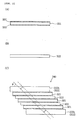
- Fig. 1 illustrates a polarization conversion element 320 in accordance with the present invention.
- Fig. 2 illustrates a method of producing a polarization separation element 330.
- Fig. 3 illustrates the bonding of first transmissive plates 321 and second transmissive plates 322.
- Fig. 4 illustrates another method of producing the polarization separation element 330.
- Fig. 5 is an enlarged sectional view of the polarization separation film 331.
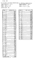
- Fig. 6 shows the thickness of each layer of the polarization separation film 331 of Fig. 5.
- Fig. 7 illustrates a graph showing simulation results of optical characteristics of the polarization separation film 331 having the structure of Fig. 6.
- Fig. 8 shows the thickness of each layer of a reflection film 332.
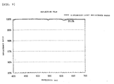
- Fig. 9 illustrates a graph showing simulation results of an s-polarized light beam reflection characteristic when the reflection film 332 having the structure of Fig. 8 is used.
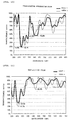
- Fig. 10 illustrates a graph showing simulation results of optical characteristics of the polarization separation film 331 in a wavelength range of 300 to 400 nm (that is, in the ultraviolet region).
- Fig. 11 illustrates a graph showing simulation results of optical characteristics of the reflection film 332 in the wavelength range of 300 to 400 nm.
- Fig. 12 illustrates the structure of a comparative-example polarization separation film and that of a comparative-example reflection film used in a conventional polarization conversion element.
- Fig. 13 illustrates a graph showing simulation results of optical characteristics of the comparative-example polarization separation film in a wavelength range of 400 to 700 nm.
- Fig. 14 illustrates a graph showing simulation results of optical characteristics in the wavelength range of 300 to 400 nm.
- Fig. 15 illustrates a graph showing simulation results of an optical characteristic of the comparative-example reflection film in the wavelength range of 400 to 700 nm.
- Fig. 16 illustrates a graph showing simulation results of optical characteristics in the wavelength range of 300 to 400 nm.
- Fig. 17 illustrates another structure of the reflection film 332.
- Fig. 18 illustrates a graph showing simulation results of an s-polarized light beam reflection characteristic when a reflection film 332A having the structure of Fig. 17 is used.
- Fig. 19 illustrates a graph showing simulation results of optical characteristics of the reflection film 332A in the wavelength range of 300 to 400 nm.
- Fig. 20 is a schematic structural view of the main portion of a projector including the polarization conversion element of the present invention.
- Fig. 1 illustrates a polarization conversion element 320 in accordance with the present invention.
- Fig. 1(A) is a plan view of the polarization conversion element 320
- Fig. 1(B) is a front view of the polarization conversion element 320.
- the polarization conversion element 320 includes a polarization separation element 330 and a plurality of ⁇ /2 retardation plates 381 selectively disposed at portions of a light-exiting surface of the polarization separation element 330.
- the polarization separation element 330 has a shape formed by alternately bonding first transmissive members 333 and second transmissive members 334, which are columnar members that are parallelogrammic in section.
- a third transmissive member 334a and a fourth transmissive member 334b, which are columnar members that are trapezoidal in section, are bonded to both ends of the polarization separation element 330.
- a plurality of polarization separation films 331 and a plurality of reflection films 332 are alternately formed on interfaces of the transmissive members 333, 334, 334a, and 334b.
- Each ⁇ /2 retardation plate 381 is selectively disposed on an image portion of a light-exiting surface in an x direction of either its corresponding polarization separation film 331 or reflection film 332. In this embodiment, each ⁇ /2 retardation plate 381 is selectively disposed on the image portion in the x direction of the light-exiting surface of its corresponding polarization separation film 331.
- the third and fourth transmissive members 334a and 334b may have the same shape as the second transmissive members 334, that is, they may be columnar members which are parallelogrammic in section. They may also be columnar members having a substantially right-angled triangular section.
- the unpolarized light beam strikes any one of the polarization separation films 331 of the polarization conversion element 320 of Fig. 1(A), the unpolarized light beam is separated into an s-polarized light beam and a p-polarized light beam by the corresponding polarization separation film 331.
- the s-polarized light beam is reflected by the corresponding polarization separation film 331. Then, it is further reflected by the corresponding reflection film 332, and leaves therefrom.
- the p-polarized light beam passes through the polarization separation film 331.
- the corresponding ⁇ /2 retardation plate 381 is disposed on an exiting plane of the p-polarized light beam which has passed through the polarization separation film 331, so that the p-polarized light beam is converted into an s-polarized light beam, and the resulting s-polarized light beam leaves therefrom. Therefore, almost all of the light beam incident to the polarization separation film 331 of the polarization conversion element 320 leaves it as s-polarized light beams.
- the corresponding retardation plate 381 is disposed on an exiting plane of an s-polarized light beam reflected by the corresponding reflection film 332.
- Fig. 2 illustrates a method of producing the polarization separation element 330.
- a plurality of first transmissive members 321 and a plurality of second transmissive plates 322 are made available.
- a polarization separating film 331 is formed on one of the surfaces of each first transmissive plate 321, while a reflection film 332 is formed on the other of the surfaces thereof.
- the polarization separation films 331 and the reflection films 332 are described in more detail below.
- first transmissive plates 321 and the second transmissive plates 322 are alternately bonded together so that the polarization separation films 331 and the reflection films 332 are alternately disposed in order to produce a composite plate 340 shown in Fig. 2(C).
- transmissive plates which are thicker than the first transmissive plates 321 and the second transmissive plates 322 may be used.
- third and fourth transmissive plates 322a and 322b are used.
- the transmissive plates 322a and 322b are thicker than the first transmissive plates 321 and the second transmissive plates 322, and are the same as the second transmissive plates 322 in that they do not have anything formed on their surfaces.
- the third and fourth transmissive plates 322a and 322b functionally act as second transmissive plates.
- the term second transmissive member 322 may be used to refer to the third and fourth transmissive plates 322a and 322b.
- the thickness of the adhesive used in bonding it is preferable that plates which are slightly thinner than the first transmissive plates 321 are used for the second transmissive plates 322.
- the thicknesses of the first transmissive plates 321 and those of the second transmissive plates 322 differ by a few percent or less.
- a transmissive block is cut out. It is preferable that ⁇ be approximately 45 degrees.
- the "planar surfaces of the composite plate” correspond to the planar surfaces of the third and fourth transmissive plates 322a and 322b which are bonded at both ends. The protruding portions at both ends are cut into substantially rectangular parallelepiped shapes.
- the first transmissive plates 321 correspond to the first transmissive members 333, while the second transmissive plates 322 correspond to the second transmissive plates 334.
- the third transmissive plate 322a corresponds to the third transmissive member 334a, while the fourth transmissive plate 322b corresponds to the fourth transmissive member 334b.
- the first transmissive plates 321 and the second transmissive plates 322 are bonded as follows.
- Fig. 3 illustrates the bonding of the first transmissive plates 321 and the second transmissive plates 322.
- a first transmissive plate 321 is bonded onto the third transmissive plate 322a with optical adhesive 327.
- the bonding is carried out by making the side of the first transmissive plate 321 where the reflection film 332 is formed face downward.
- the optical adhesive 327 which has not yet been cured is irradiated with ultraviolet light (UV) beams through the polarization separation film 331, the first transmissive plate 321, and the reflection film 332 in order to cure the optical adhesive 327.
- UV ultraviolet light
- a second transmissive plate 322 is bonded onto the first transmissive plate 321 which has been bonded as shown in Fig. 3(A).
- the optical adhesive 327 which has not yet been cured is irradiated with ultraviolet light beams through the second transmissive plate 322 in order to cure the optical adhesive 327.
- FIG. 3(C) As shown in Fig. 3(C), using optical adhesive 327, another first transmissive plate 321 is, as in Fig. 3(A), bonded onto the second transmissive plate 322 which has been bonded as shown in Fig. 3(B).
- the first transmissive plates 321 and the second transmissive plates 322 are bonded together, respectively.
- the fourth transmissive plate 322b is bonded in a way similar to that shown in Fig. 3(B).
- the bonding is started from the third transmissive plate 322a side. However, it may be started from the fourth transmissive plate 322b side. Ultraviolet light beams may be irradiated from the third transmissive plate 322a side.
- Fig. 4 illustrates another method of producing the polarization separation element 330.
- first transmissive plates 321 and second transmissive plates 322 are made available.
- reflection films 332 are formed at sides of corresponding second transmissive plates 322 to which the reflection films 332 are bonded by the bonding step shown in Fig. 3.
- the first transmissive plates 321 and the second transmissive plates 322 are alternately bonded in order to produce a composite plate 340a formed in such a way that the polarization separation films 331 and the reflection films 332 are alternately disposed.
- the composite plate 340a produced in this way is, as in Fig. 2(C), cut along cutting planes (indicated by broken lines in the figure) which are substantially parallel to each other and which extend at a predetermined angle ⁇ from planar surfaces thereof, the protruding portions at both ends are cut into a substantially rectangular parallelepiped shape, and the surfaces (that is, cut surfaces) are polished, so that a polarization separation element 330' similar to the polarization separation element 330 can be produced.
- first transmissive plates 321 and the second transmissive plates 322 can be bonded in a way similar to the way the first and second transmissive plates are bonded in Fig. 3.
- Fig. 5 is an enlarged sectional view of a polarization separation film 331.
- the polarization separation film 331 is a dielectric multilayered film formed on the corresponding first transmissive member 333, and includes a multilayered structural section 331a in which two types of materials are alternately placed upon each other so that 49 layers are formed, and a covering layer 331b formed on the multi-layered structural section 331a.
- the polarization separation film 331 is formed by successively placing its layers one layer at a time onto the surface of the corresponding first transmissive plate 321 which corresponds to the first transmissive member 333.
- the first transmissive member 333 onto which the layers of the polarization separation film 331 has been placed is bonded to the corresponding second transmissive member 334 (that is, the second transmissive plate 322) or the third transmissive member 334a (that is, the third transmissive plate 322a) with optical adhesive 327.
- Fig. 5 illustrates the case where it is bonded to the second transmissive member 334.
- the covering layer 331b functions to increase an adhesive property between the polarization separation film 331 and the second transmissive member 334.
- the multi-layered structural section 331a comprises a laminated structure of layers (hereunder called layers L) which are formed on the first transmissive member 333 with a refractive index of approximately 1.5 and which have relatively small refractive indices compared to that of the first transmissive member 333, and layers (hereunder called layers H) with relatively large refractive indices.
- layers L layers which are formed on the first transmissive member 333 with a refractive index of approximately 1.5 and which have relatively small refractive indices compared to that of the first transmissive member 333, and layers (hereunder called layers H) with relatively large refractive indices.
- layers L1 layers
- H layers
- the covering layer 331b has a refractive index which is substantially intermediate between those of the materials of the layers H and the layers L.
- transmissive members 333, 334, 334a, and 334b may be used to form the transmissive members 333, 334, 334a, and 334b, so that, for example, a white transmissive plate with a refractive index of approximately 1.52, or an optical glass such as BK7-S (product of Schott) may be used.
- MgF 2 with a refractive index of approximately 1.38 is used as a material for the layers L of the polarization separation film 331, whereas MgO having a refractive index of approximately 1.73 is used as a material for the layers H.
- SiO 2 with a refractive index of approximately 1.44 is used as a material for the covering layer 331b.
- the refractive index of each layer changes as a result of, for example, absorption of moisture in the atmosphere.
- the "refractive index” is maintained in a state in which the polarization separation film 331 is exposed to the atmosphere for a long period of time.
- Fig. 6 shows the thickness of each layer of the polarization separation film 331 shown in Fig. 5.
- the structure thereof is used when a design wavelength ⁇ is 600 nm.
- the design wavelength ⁇ is the initial set value when a film is being designed, and the thickness of each layer is determined so that a required transmission/reflection characteristic can be obtained at this design wavelength.
- As the design wavelength ⁇ a wavelength of a primary light component used in the optical element is selected.
- the polarization conversion element 320 of the embodiment is used to convert the polarizations of three color light beams, R, G, and B light beams, and, here, a wavelength near the wavelength of red light (that is, 600 nm) is selected as the design wavelength.
- a wavelength near the wavelength of red light that is, 600 nm
- value D in the right column represents a value obtained by dividing the optical thickness of each layer (that is, the thickness obtained by multiplying the refractive index n of each material of each layer to the actual film thickness d of each layer) by 1/4th the design wavelength ⁇ . Therefore, each actual film thickness d is a value obtained by multiplying its corresponding value D by ⁇ /4 and dividing the product by its corresponding refractive index n.
- the refractive index of each layer L is used for the refractive index n thereof
- the refractive index of each layer H is used for the refractive index n thereof.
- the optical thickness of each layer of the multilayered structural section 331a is of the order of ⁇ /4, different values may be used. Only the optical thickness of the covering layer 331b is 3 ⁇ ( ⁇ /4).
- Fig. 7 is a graph showing simulation results of optical characteristics of the polarization separation film 331 having the structure of Fig. 6.
- the refractive index of each layer changes by an amount of the order of 0.1.
- the simulation results of Fig. 7 are values obtained by solving each film characteristic matrix while considering the wavelength characteristic of the refractive index of each layer.
- the polarization separation film 331 is such that the transmittance ratio of a p-polarized light beam at an angle of incidence of approximately 45 degrees is at least 99.2%, while the reflectance ratio of an s-polarized light beam is at least 97.5%.
- the covering layer 331b is disposed to increase the adhesive property between the multilayered structural section 331a and the second transmissive member 334, so that it virtually does not affect the optical characteristics of the polarization separation film 331. In other words, even if the covering layer 331b is not disposed, results similar to the simulation results of Fig. 7 can be obtained, so that the covering layer 331b does not have to be disposed.
- Fig. 7 shows the simulation results obtained when the light beams are incident from the L1 layer side. However, similar results can be obtained when the light beams are incident from the covering layer 331b side.
- the reflection film 332 is also a dielectric multilayered film formed on either the first transmissive member 333 or the second transmissive member 334, and comprises two types of materials alternately placed upon each other.
- Fig. 8 shows the thickness of each layer of the reflection film 332.
- SiO 2 with a refractive index of approximately 1.44 is used as a material for the layers L
- TiO 2 with a refractive index of approximately 2.266 is used as a material for the layers H.
- 31 layers, L1, H2, L3, H4, ... H30, L31, are successively placed upon each other in that order on the first transmissive member 333. In the method shown in Fig. 4, they are placed on the second transmissive member 334.
- Fig. 9 is a graph showing simulation results of the reflection characteristic of an s-polarized light beam when the reflection film 332 having the structure shown in Fig. 8 is used.
- the reflection film 332 having the structure shown in Fig. 6(B) in the visible wavelength range of 400 to 700 nm, it is possible to obtain a reflectance ratio of at least 99.8% for an s-polarized light beam at an angle of incidence of approximately 45 degrees, as shown in Fig. 9.
- the reflection film 332 produces similar simulation results regardless of whether light beams are incident from the L1 layer side or are incident from the L31 layer side.
- the first and second transmissive plates 321 and 322 corresponding to the respective transmissive members 333 and 334 of the polarization conversion element 320 are bonded with the optical adhesive 327, and, as shown in Fig. 3, the optical adhesive 327 is irradiated with ultraviolet light beams through the polarization separation films 331 and the reflection films 332 in order to be cured. Therefore, it is preferable that the polarization separation films 331 and the reflection films 332 transmit ultraviolet light beams therethrough. In particular, it is preferable that they transmit as much ultraviolet light beams therethrough in order to reduce the time required to carry out the bonding.
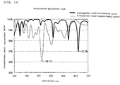
- Fig. 10 is a graph showing simulation results of optical characteristics of the polarization separation film 331 in a wavelength range of 300 to 400 nm (that is, the ultraviolet range).
- the thick line in Fig. 10 represents the transmittance ratio of the polarization separation film 331 in a state (hereunder referred to as "state 1") where the polarization separation film 331 is sandwiched by its corresponding first transmissive plate 321 and its corresponding second transmissive plate 322, whereas the thin line represents the transmittance ratio of the polarization separation film 331 in a state (hereunder referred to as "state 2") where one side of the polarization separation film is in contact with air.
- states 1 and 2 two characteristics in states 1 and 2 are shown due to the following reasons. As shown in Fig.
- the polarization separation films and the reflection films may be sandwiched by their corresponding first transmissive members 321 and second transmissive members 322, or one side thereof may be in contact with air.
- the transmittance characteristics of the films vary with the media at the interfaces. Therefore, in Fig. 10, the characteristics in the states 1 and 2 are shown.
- the transmittance ratio is at least 18.7% in the state 1, and at least 19.9% in the state 2.
- the transmittance ratio is at least 45.8% in the state 1, and at least 47.6% in the state 2.
- Fig. 11 is a graph showing simulation results of optical characteristics in the wavelength range of 300 to 400 nm of a reflection film 332.
- the thick line in Fig. 11 represents the transmittance ratio in a state (hereunder called “state 3") where the reflection film 332 is sandwiched by its corresponding first transmissive plate 321 and second transmissive plate 322, while the thin line represents the transmittance ratio in a state (hereunder called “state 4") where one side of the reflection film is in contact with air.
- the light transmittance ratio is at least 28.5% in the state 3, and at least 19.7% in the state 4.
- the transmittance ratio is at least 71.0% in the state 3, and at least 65.5% in the state 4.
- Fig. 12 shows the structures of comparative examples of a polarization separation film and a reflection film used in a conventional polarization conversion element.
- the comparative-example polarization separation film and reflection film are the same as the polarization separation films 331 and the reflection films 332 used in the above-described embodiment except that the thicknesses of the layers are different.
- Fig. 13 illustrates a graph showing simulation results of optical characteristics in the wavelength range of 400 to 700 nm (that is, in the visible range).
- Fig. 14 illustrates a graph showing simulation results of optical characteristics in the wavelength range of 300 to 400 nm (that is, in the ultraviolet range).
- the comparative-example polarization separation film is such that, in the visible region, the p-polarized light beam transmittance ratio is at least 96.1%, and the s-polarized light beam reflectance ratio is at least 97.0%.
- the polarization separation film 331 used in the embodiment is such that, in the visible region, the p-polarized light beam transmittance ratio is at least 99.2%, and the s-polarized light beam reflectance ratio is at least 98.1%. Therefore, in the visible range, the polarization separation film 331 used in the above-described embodiment has transmission/reflection characteristics which are better than those of the comparative-example polarization separation film. Therefore, like the conventional polarization separation element, the polarization separation element can be constructed to transmit a p-polarized light beam and reflect an s-polarized light in the visible region with high efficiency.
- the comparative-example polarization separation film is such that, in the wavelength range of 300 to 400 nm (that is, the ultraviolet region), the transmittance ratio of light is at least 10.3% in the state 1, and at least 8.4% in the state 2. In particular, even in the wavelength range of 365 ⁇ 30 nm, it is at least 26.3% in the state 1, and at least 18.3% in the state 2.
- the light transmittance ratio of the polarization separation film 331 used in the above-described embodiment is at least 18.7% in the state 1 and at least 19.9% in the state 2.
- the transmittance ratio is at least 45.8% in the state 1 and at least 47.6% in the state 2. Therefore, it can be seen that, in the wavelength range of 300 to 400 nm, the transmittance ratio of the polarization separation film 331 used in the embodiment is at least 1.8 times that of the comparative-example polarization separation film in the state 1, and at least 1.7 times that of the comparative-example polarization separation film in the state 2.
- the transmittance ratio is at least 2.3 times that of the comparative-example polarization separation film in the state 1, and at least 2.6 times that of the comparative-example polarization separation film in the state 2.
- the polarization separation film 331 used in the embodiment has greater transmittance ratios in the ultraviolet region than the comparative-example polarization separation film.
- the time required to cure the optical adhesive 327 can be made shorter in the step of bonding the transmissive plates when producing the above-described polarization separation element. This makes it possible to reduce the number of man-hours required to produce the polarization conversion element.
- Fig. 15 illustrates a graph showing simulation results of optical characteristics in the wavelength range of 400 to 700 nm (that is, the visible region) for the comparative-example reflection film.
- Fig. 16 illustrates a graph showing simulation results of optical characteristics in the wavelength range of 300 to 400 nm (that is, the ultraviolet region).
- the s-polarized light beam reflectance ratio of the comparative-example reflection film is at least 98.9%.
- the s-polarized light beam reflectance ratio of the reflection film 332 used in the embodiment is at least 99.8%. Therefore, in the visible region, the reflection characteristic of the reflection film 332 used in the embodiment is better than that of the comparative-example reflection film. Consequently, as is conventionally the case, a polarization separation element which reflects s-polarized light beams with high efficiency in the visible region can be constructed.
- the ultraviolet light transmittance ratio of the comparative-example reflection film is at least 15.4% in the state 3 and at least 11.1% in the state 4, and this is also true in the wavelength range of 365 ⁇ 30 nm.
- the light transmittance ratio of the reflection film 332 used in the embodiment is at least 28.5% in the state 3 and at least 19.7% in the state 4.
- the transmittance ratio of the reflection film 332 used in the embodiment is at least 1.8 times that of the comparative-example reflection film in the state 3 and at least 1.7 times that of the comparative-example reflection film in the state 4.
- the transmittance ratio is at least 4.6 times that of the comparative-example reflection film in the state 3 and at least 5.9 times that of the comparative-example reflection film in the state 4.
- the transmittance ratios of the reflection film 332 used in the embodiment are greater than those of the comparative-example reflection film.
- the time required to cure the optical adhesive 327 can be made shorter in the step of bonding the transmissive plates when producing the above-described polarization separation element. This makes it possible to reduce the number of man-hours required to produce the polarization conversion element.
- the transmission characteristics in the ultraviolet region are improved compared to those of a conventional polarization conversion element while making the usual reflection and transmission characteristics in the visible region comparable to or better than those of the conventional polarization conversion element, it is possible to shorten the length of time required to bond the transmissive plates together during the manufacturing process. This makes it possible to reduce the number of man-hours required to produce the polarization conversion element.
- Fig. 17 illustrates another structure of the reflection film 332.
- SiO 2 with a refractive index of approximately 1.44 is used as a material for the layers L
- Ta 2 O 5 with a refractive index of approximately 2.18 is used as a material for the layers H.
- Fig. 18 illustrates a graph of simulated results of an s-polarized light beam reflection characteristic when the reflection film 332A having the structure described in Fig. 17 is used.
- the s-polarized light beam reflectance ratio in the visible wavelength range of 400 to 700 nm is at least 98.9%, making it possible to obtain reflectance ratios which are comparable to those of the comparative-example reflection film.
- Fig. 19 illustrates a graph showing simulation results of an optical characteristic of the reflection film 332A in the wavelength range of 300 to 400 nm.
- the transmittance ratio is at least 16.6% in the state 3 and at least 11.6% in the state 4.
- the transmittance ratio is at least 75.7% in the state 3 and at least 67.4% in the state 4. Therefore, it can be seen that, in the wavelength range of 300 to 400 nm, the transmittance ratio of the reflection film 332A is at least 1.07 times that of the comparative-example reflection film in the state 3 and at least 1.04 times that of the comparative-example reflection film in the state 4.
- the transmittance ratio is at least 4.9 times that of the comparative-example reflection film in the state 3 and at least 6.0 times that of the comparative-example reflection film in the state 4. Even with the reflection film 332A, in the ultraviolet region, a transmittance characteristic which is substantially the same as that of the reflection film 332 (shown in Fig. 11) can be obtained.
- the transmittance ratios of the reflection film 332A are greater. Therefore, it is possible to shorten the time required to cure the optical adhesive 327 in the step of bonding the above-described transmissive plates. Thus, the number of man-hours required to produce the polarization conversion element can be reduced.
- the degree of light absorption of Ta 2 O 5 used to form the reflection film 332A can be made smaller than that of TiO 2 used to form the reflection film 332. Therefore, the reflection film used to provide an s-polarized light beam reflectance ratio in the ultraviolet region while maintaining the light transmittance ratios can be easily formed.
- FIG. 20 is a schematic structural view illustrating the main portion of a projector including the polarization conversion element in accordance with the present invention.
- a projector 800 comprises a polarization illumination device 50, dichroic mirrors 801 and 804, reflection mirrors 802, 807 and 809, relay lenses 806, 808, and 810, three liquid crystal light valves 803, 805, and 811, a cross dichroic prism 813, and a projection lens 814.
- the polarization illumination device 50 includes a light source 60 and a polarization generation device 70.
- An unpolarized light beam including an s-polarized light beam component and a p-polarized light beam component exits from the light source 60.
- the polarization generation device 70 converts the light beam which has exited the light source 60 into one type of linearly polarized light beam (an s-polarized light beam in the embodiment) whose polarization directions are substantially aligned, and the resulting polarized light beam illuminates illumination areas.
- the three liquid crystal light valves 803, 805, and 811 correspond to the illumination areas.
- the polarization generation device 70 includes a first optical element 200 and a second optical element 400.
- the first optical element 200 is a lens array in which small lenses with rectangular contours are disposed in a matrix arrangement.
- the second optical element 400 (shown in Fig. 20) includes an optical element 300 and a light exiting side lens 390.
- the optical element 300 includes a condensing lens array 310 and two polarization conversion elements 320a and 320b.
- the condensing lens array 310 has the same structure as the first optical element 200, and is disposed so as to oppose the first optical element 200.
- the condensing lens array 310 functions, along with the first optical element 200, to gather a plurality of partial light beams divided at the small lenses in order to guide them to incident areas of the polarization conversion elements 320a and 320b.
- the polarization conversion elements 320a and 320b are disposed so that the polarization separation films 331 and the reflection films 332 of the polarization conversion element 320 (shown in Fig.
- the light beam which has exited the light source 60 is converted into substantially one type of linearly polarized light beam (an s-polarized light beam in the embodiment) by the polarization generation device 70.
- the light exiting side lens 390 functions to superimpose the plurality of partial light beams exiting from the optical element 300 onto each of the liquid crystal light valves 803, 805, and 811.
- the light beam which has exited the polarization illumination device 50 is separated into three color light beams, a red light beam, a green light beam, and a blue light beam, by the dichroic mirrors 801 and 804 functioning together as a color light beam separation optical system.
- the blue light beam is guided by the relay system 850 which is comprised of three relay lenses 806, 808, and 810, and two reflection mirrors 807 and 809 to the liquid crystal light valve 811.
- the separated color light beams are modulated by their respective color-light liquid crystal light valves 803, 805, and 811 in accordance with provided image information (image signals). These liquid crystal light valves 803, 805, and 811 correspond to light-modulating devices in the present invention.
- the color light beams modulated by their respective liquid crystal light valves 803, 805, and 811 are synthesized by the cross dichroic prism 813 serving as a color-light synthesizing optical system, and the resulting synthesized light beams are projected onto a screen 815 by the projection lens 814 serving as a projection optical system. This causes a color image to be displayed on the screen 815.
- the structures and functions of the parts of the projector such as those shown in Fig. 20 are discussed in detail in Japanese Unexamined Patent Application Publication No. 10-177151 disclosed by the present applicant, so that they will not be described in detail herein.
- the polarization conversion elements 320a and 320b produced by a method of the present invention are used in the polarization illumination device 50 of the projector 800, the light beam from the light source 60 incident on the polarization generation device 70 is converted into a desired linearly polarized light beam (an s-polarized light beam in the embodiment) with high efficiency, and the polarized light beam exits the polarization illumination device 50. Therefore, in the projector including the polarization conversion elements 320a and 320b, the intensity of the image projected onto the screen 815 can be increased.
- the number of man-hours required to produce the polarization conversion elements 320a and 320b can be made less than that required to produce the comparative-example polarization conversion element, the number of man-hours required to manufacture the entire projector can be decreased.
Landscapes
- Physics & Mathematics (AREA)
- General Physics & Mathematics (AREA)
- Optics & Photonics (AREA)
- Polarising Elements (AREA)
- Devices For Indicating Variable Information By Combining Individual Elements (AREA)
Applications Claiming Priority (2)
| Application Number | Priority Date | Filing Date | Title |
|---|---|---|---|
| JP11197687A JP2001021719A (ja) | 1999-07-12 | 1999-07-12 | 偏光分離素子、偏光変換素子および投写型表示装置 |
| JP19768799 | 1999-07-12 |
Publications (2)
| Publication Number | Publication Date |
|---|---|
| EP1070976A2 true EP1070976A2 (de) | 2001-01-24 |
| EP1070976A3 EP1070976A3 (de) | 2001-10-10 |
Family
ID=16378689
Family Applications (1)
| Application Number | Title | Priority Date | Filing Date |
|---|---|---|---|
| EP00305896A Ceased EP1070976A3 (de) | 1999-07-12 | 2000-07-12 | Polarisationsstrahlteiler, Polarisationswandlungselement und Projektor |
Country Status (6)
| Country | Link |
|---|---|
| US (1) | US6402322B1 (de) |
| EP (1) | EP1070976A3 (de) |
| JP (1) | JP2001021719A (de) |
| KR (1) | KR100453119B1 (de) |
| CN (1) | CN1179220C (de) |
| TW (1) | TWM264502U (de) |
Cited By (3)
| Publication number | Priority date | Publication date | Assignee | Title |
|---|---|---|---|---|
| EP2919045A4 (de) * | 2012-11-08 | 2016-06-08 | Asukanet Co Ltd | Herstellungsverfahren für lichtsteuerungsplatte |
| US9513486B2 (en) | 2011-10-24 | 2016-12-06 | Asukanet Company, Ltd. | Optical imaging apparatus |
| US9523859B2 (en) | 2012-02-28 | 2016-12-20 | Asukanet Company, Ltd. | Volumetric-image forming system and method thereof |
Families Citing this family (6)
| Publication number | Priority date | Publication date | Assignee | Title |
|---|---|---|---|---|
| JP4483840B2 (ja) | 2006-09-04 | 2010-06-16 | セイコーエプソン株式会社 | 画像表示装置 |
| CN101808818B (zh) * | 2007-09-28 | 2013-01-09 | Jsr株式会社 | 液晶面板和液晶面板用光学膜组件 |
| JP5953835B2 (ja) * | 2011-09-07 | 2016-07-20 | セイコーエプソン株式会社 | プロジェクター |
| WO2014208725A1 (ja) * | 2013-06-27 | 2014-12-31 | デクセリアルズ株式会社 | 偏光変換素子、偏光変換素子の製造方法及び光学機器 |
| JP6287037B2 (ja) * | 2013-10-16 | 2018-03-07 | セイコーエプソン株式会社 | 偏光変換素子、プロジェクター、および偏光変換素子の製造方法 |
| JP7663612B2 (ja) * | 2020-06-25 | 2025-04-16 | マジック リープ, インコーポレイテッド | ウェアラブルディスプレイ内の光透過アーチファクトの調整可能減衰 |
Family Cites Families (15)
| Publication number | Priority date | Publication date | Assignee | Title |
|---|---|---|---|---|
| US96A (en) * | 1836-12-02 | Temple eor weaving- cloth | ||
| US2748659A (en) * | 1951-02-26 | 1956-06-05 | Jenaer Glaswerk Schott & Gen | Light source, searchlight or the like for polarized light |
| NL8303109A (nl) * | 1983-09-08 | 1985-04-01 | Philips Nv | Werkwijze voor het aan elkaar bevestigen van twee delen. |
| KR920010621B1 (ko) | 1988-09-12 | 1992-12-12 | 후지쓰 가부시끼가이샤 | 광학부품용기재와그의제조방법및그를사용한광학제품 |
| JPH0643305A (ja) * | 1992-07-23 | 1994-02-18 | Fujitsu Ltd | 光カプラ膜 |
| JPH0682623A (ja) | 1992-08-31 | 1994-03-25 | Nippon Telegr & Teleph Corp <Ntt> | 光ビーム分離素子及びその作製方法 |
| JPH07294906A (ja) * | 1994-04-28 | 1995-11-10 | Nippon Hoso Kyokai <Nhk> | 映像表示装置 |
| JPH1039136A (ja) * | 1996-07-25 | 1998-02-13 | Seiko Epson Corp | 光学素子および投写型表示装置 |
| JP3486516B2 (ja) | 1996-07-25 | 2004-01-13 | セイコーエプソン株式会社 | 光学素子 |
| US6404550B1 (en) | 1996-07-25 | 2002-06-11 | Seiko Epson Corporation | Optical element suitable for projection display apparatus |
| US5912762A (en) | 1996-08-12 | 1999-06-15 | Li; Li | Thin film polarizing device |
| JPH1096815A (ja) * | 1996-09-25 | 1998-04-14 | Sumitomo Bakelite Co Ltd | シート状偏光素子 |
| JP3298437B2 (ja) | 1996-12-18 | 2002-07-02 | セイコーエプソン株式会社 | 光学素子、偏光照明装置および投写型表示装置 |
| JPH11271682A (ja) * | 1998-03-20 | 1999-10-08 | Fujitsu Ltd | 偏光変換装置及び液晶表示装置 |
| JPH11305167A (ja) * | 1998-04-21 | 1999-11-05 | Canon Inc | 偏光変換素子及びそれを用いた画像投射装置 |
-
1999
- 1999-07-12 JP JP11197687A patent/JP2001021719A/ja active Pending
-
2000
- 2000-05-30 TW TW093211621U patent/TWM264502U/zh not_active IP Right Cessation
- 2000-06-22 US US09/598,482 patent/US6402322B1/en not_active Expired - Lifetime
- 2000-07-11 CN CNB001201301A patent/CN1179220C/zh not_active Expired - Fee Related
- 2000-07-11 KR KR10-2000-0039664A patent/KR100453119B1/ko not_active Expired - Fee Related
- 2000-07-12 EP EP00305896A patent/EP1070976A3/de not_active Ceased
Non-Patent Citations (1)
| Title |
|---|
| BASS M.: 'Handbook of Optics I. Fundamentals, Techniques, and Design', Chapter 42.4: 'Optical Coating Materials', 1995, MCGRAW.HILL, NEW YORK * |
Cited By (3)
| Publication number | Priority date | Publication date | Assignee | Title |
|---|---|---|---|---|
| US9513486B2 (en) | 2011-10-24 | 2016-12-06 | Asukanet Company, Ltd. | Optical imaging apparatus |
| US9523859B2 (en) | 2012-02-28 | 2016-12-20 | Asukanet Company, Ltd. | Volumetric-image forming system and method thereof |
| EP2919045A4 (de) * | 2012-11-08 | 2016-06-08 | Asukanet Co Ltd | Herstellungsverfahren für lichtsteuerungsplatte |
Also Published As
| Publication number | Publication date |
|---|---|
| CN1179220C (zh) | 2004-12-08 |
| JP2001021719A (ja) | 2001-01-26 |
| US6402322B1 (en) | 2002-06-11 |
| EP1070976A3 (de) | 2001-10-10 |
| TWM264502U (en) | 2005-05-11 |
| KR20010015285A (ko) | 2001-02-26 |
| KR100453119B1 (ko) | 2004-10-15 |
| CN1280302A (zh) | 2001-01-17 |
Similar Documents
| Publication | Publication Date | Title |
|---|---|---|
| EP0829739B1 (de) | Polarisationsstrahlteiler, verfahren zu seiner herstellung und projektionsanzeige | |
| US6690521B2 (en) | Light-selective prism, projection display apparatus using the same, and method of manufacturing light-selective prism | |
| JPH04212102A (ja) | ダイクロイックミラーおよび該ミラーを用いた投写型表示装置 | |
| KR100408381B1 (ko) | 광학 부품 및 그것을 사용한 프로젝터 | |
| US6402322B1 (en) | Polarization separation element, polarization conversion element, and projector | |
| JP2002182307A (ja) | 投射型表示装置 | |
| US6669797B2 (en) | Manufacturing method for polarizing conversion elements | |
| JP2001523351A (ja) | カラー投影プリズム | |
| US20100245772A1 (en) | Optical filter, projection display, and method for manufacturing optical filter | |
| JP3399449B2 (ja) | 偏光変換素子の製造方法 | |
| JP3065081B1 (ja) | 投写型表示装置 | |
| JP2000075427A (ja) | 投射型表示装置 | |
| JP2008083214A (ja) | クロスプリズムの製造方法およびクロスプリズム | |
| JP2004170677A (ja) | 偏光分離素子 | |
| TW470853B (en) | Full color image display projection system | |
| JPH1031111A (ja) | 偏光分離装置及びそれを用いた投射表示装置 | |
| JPH09127317A (ja) | ダイクロイックプリズム | |
| JPH10268234A (ja) | 偏光色分解合成装置 | |
| JP2002131544A (ja) | 光学偏光素子 | |
| JPH09318908A (ja) | 投写型表示装置 | |
| JP2010039301A (ja) | プロジェクタ装置 | |
| JPWO1997034173A1 (ja) | 偏光分離装置及びその製造方法並びに投写型表示装置 |
Legal Events
| Date | Code | Title | Description |
|---|---|---|---|
| PUAI | Public reference made under article 153(3) epc to a published international application that has entered the european phase |
Free format text: ORIGINAL CODE: 0009012 |
|
| AK | Designated contracting states |
Kind code of ref document: A2 Designated state(s): AT BE CH CY DE DK ES FI FR GB GR IE IT LI LU MC NL PT SE Kind code of ref document: A2 Designated state(s): DE FR GB |
|
| AX | Request for extension of the european patent |
Free format text: AL;LT;LV;MK;RO;SI |
|
| PUAL | Search report despatched |
Free format text: ORIGINAL CODE: 0009013 |
|
| AK | Designated contracting states |
Kind code of ref document: A3 Designated state(s): AT BE CH CY DE DK ES FI FR GB GR IE IT LI LU MC NL PT SE |
|
| AX | Request for extension of the european patent |
Free format text: AL;LT;LV;MK;RO;SI |
|
| 17P | Request for examination filed |
Effective date: 20020409 |
|
| AKX | Designation fees paid |
Free format text: DE FR GB |
|
| 17Q | First examination report despatched |
Effective date: 20020816 |
|
| STAA | Information on the status of an ep patent application or granted ep patent |
Free format text: STATUS: THE APPLICATION HAS BEEN REFUSED |
|
| 18R | Application refused |
Effective date: 20051009 |