EP1071197A2 - Gleichstrom -Gleichstromwandlerschaltung - Google Patents
Gleichstrom -Gleichstromwandlerschaltung Download PDFInfo
- Publication number
- EP1071197A2 EP1071197A2 EP00203454A EP00203454A EP1071197A2 EP 1071197 A2 EP1071197 A2 EP 1071197A2 EP 00203454 A EP00203454 A EP 00203454A EP 00203454 A EP00203454 A EP 00203454A EP 1071197 A2 EP1071197 A2 EP 1071197A2
- Authority
- EP
- European Patent Office
- Prior art keywords
- rectifier
- converter
- secondary winding
- conversion circuit
- transistor
- Prior art date
- Legal status (The legal status is an assumption and is not a legal conclusion. Google has not performed a legal analysis and makes no representation as to the accuracy of the status listed.)
- Withdrawn
Links
Images


Classifications
-
- H—ELECTRICITY
- H02—GENERATION; CONVERSION OR DISTRIBUTION OF ELECTRIC POWER
- H02J—ELECTRIC POWER NETWORKS; CIRCUIT ARRANGEMENTS OR SYSTEMS FOR SUPPLYING OR DISTRIBUTING ELECTRIC POWER; SYSTEMS FOR STORING ELECTRIC ENERGY
- H02J3/00—Circuit arrangements for AC mains or AC distribution networks
- H02J3/01—Arrangements for reducing harmonics or ripples
-
- H—ELECTRICITY
- H02—GENERATION; CONVERSION OR DISTRIBUTION OF ELECTRIC POWER
- H02J—ELECTRIC POWER NETWORKS; CIRCUIT ARRANGEMENTS OR SYSTEMS FOR SUPPLYING OR DISTRIBUTING ELECTRIC POWER; SYSTEMS FOR STORING ELECTRIC ENERGY
- H02J3/00—Circuit arrangements for AC mains or AC distribution networks
- H02J3/18—Arrangements for adjusting, eliminating or compensating reactive power in networks
- H02J3/1821—Arrangements for adjusting, eliminating or compensating reactive power in networks using shunt compensators
- H02J3/1835—Arrangements for adjusting, eliminating or compensating reactive power in networks using shunt compensators with stepless control
- H02J3/1842—Arrangements for adjusting, eliminating or compensating reactive power in networks using shunt compensators with stepless control having reactive elements actively controlled by bridge converters, e.g. active filters or static compensators [STATCOM]
-
- H—ELECTRICITY
- H02—GENERATION; CONVERSION OR DISTRIBUTION OF ELECTRIC POWER
- H02M—APPARATUS FOR CONVERSION BETWEEN AC AND AC, BETWEEN AC AND DC, OR BETWEEN DC AND DC, AND FOR USE WITH MAINS OR SIMILAR POWER SUPPLY SYSTEMS; CONVERSION OF DC OR AC INPUT POWER INTO SURGE OUTPUT POWER; CONTROL OR REGULATION THEREOF
- H02M3/00—Conversion of DC power input into DC power output
- H02M3/22—Conversion of DC power input into DC power output with intermediate conversion into AC
- H02M3/24—Conversion of DC power input into DC power output with intermediate conversion into AC by static converters
- H02M3/28—Conversion of DC power input into DC power output with intermediate conversion into AC by static converters using discharge tubes with control electrode or semiconductor devices with control electrode to produce the intermediate AC
- H02M3/325—Conversion of DC power input into DC power output with intermediate conversion into AC by static converters using discharge tubes with control electrode or semiconductor devices with control electrode to produce the intermediate AC using devices of a triode or a transistor type requiring continuous application of a control signal
- H02M3/335—Conversion of DC power input into DC power output with intermediate conversion into AC by static converters using discharge tubes with control electrode or semiconductor devices with control electrode to produce the intermediate AC using devices of a triode or a transistor type requiring continuous application of a control signal using semiconductor devices only
- H02M3/33569—Conversion of DC power input into DC power output with intermediate conversion into AC by static converters using discharge tubes with control electrode or semiconductor devices with control electrode to produce the intermediate AC using devices of a triode or a transistor type requiring continuous application of a control signal using semiconductor devices only having several active switching elements
-
- H—ELECTRICITY
- H02—GENERATION; CONVERSION OR DISTRIBUTION OF ELECTRIC POWER
- H02M—APPARATUS FOR CONVERSION BETWEEN AC AND AC, BETWEEN AC AND DC, OR BETWEEN DC AND DC, AND FOR USE WITH MAINS OR SIMILAR POWER SUPPLY SYSTEMS; CONVERSION OF DC OR AC INPUT POWER INTO SURGE OUTPUT POWER; CONTROL OR REGULATION THEREOF
- H02M7/00—Conversion of AC power input into DC power output; Conversion of DC power input into AC power output
- H02M7/02—Conversion of AC power input into DC power output without possibility of reversal
- H02M7/04—Conversion of AC power input into DC power output without possibility of reversal by static converters
- H02M7/12—Conversion of AC power input into DC power output without possibility of reversal by static converters using discharge tubes with control electrode or semiconductor devices with control electrode
- H02M7/21—Conversion of AC power input into DC power output without possibility of reversal by static converters using discharge tubes with control electrode or semiconductor devices with control electrode using devices of a triode or transistor type requiring continuous application of a control signal
- H02M7/217—Conversion of AC power input into DC power output without possibility of reversal by static converters using discharge tubes with control electrode or semiconductor devices with control electrode using devices of a triode or transistor type requiring continuous application of a control signal using semiconductor devices only
-
- Y—GENERAL TAGGING OF NEW TECHNOLOGICAL DEVELOPMENTS; GENERAL TAGGING OF CROSS-SECTIONAL TECHNOLOGIES SPANNING OVER SEVERAL SECTIONS OF THE IPC; TECHNICAL SUBJECTS COVERED BY FORMER USPC CROSS-REFERENCE ART COLLECTIONS [XRACs] AND DIGESTS
- Y02—TECHNOLOGIES OR APPLICATIONS FOR MITIGATION OR ADAPTATION AGAINST CLIMATE CHANGE
- Y02E—REDUCTION OF GREENHOUSE GAS [GHG] EMISSIONS, RELATED TO ENERGY GENERATION, TRANSMISSION OR DISTRIBUTION
- Y02E40/00—Technologies for an efficient electrical power generation, transmission or distribution
- Y02E40/20—Active power filtering [APF]
-
- Y—GENERAL TAGGING OF NEW TECHNOLOGICAL DEVELOPMENTS; GENERAL TAGGING OF CROSS-SECTIONAL TECHNOLOGIES SPANNING OVER SEVERAL SECTIONS OF THE IPC; TECHNICAL SUBJECTS COVERED BY FORMER USPC CROSS-REFERENCE ART COLLECTIONS [XRACs] AND DIGESTS
- Y02—TECHNOLOGIES OR APPLICATIONS FOR MITIGATION OR ADAPTATION AGAINST CLIMATE CHANGE
- Y02E—REDUCTION OF GREENHOUSE GAS [GHG] EMISSIONS, RELATED TO ENERGY GENERATION, TRANSMISSION OR DISTRIBUTION
- Y02E40/00—Technologies for an efficient electrical power generation, transmission or distribution
- Y02E40/40—Arrangements for reducing harmonics
Definitions
- each of the diodes have been replaced by a MOSFET transistor (also shown with their respective body diodes) that operates in the cut-off and switched-on states in synchronism with the alternating signal coming from the secondary winding of the transformer.
- MOSFET transistor also shown with their respective body diodes
- the technical problem to be overcome consists in preventing the flow of current through the body diode of the MOSFET transistors in the self-driven synchronous rectifier, thereby reducing its losses and enhancing the overall efficiency of the whole assembly.
- the DC/DC conversion circuit in accordance with the invention, comprise a DC/AC converter that includes means for generating an alternating signal with a square waveform that does not take zero instantaneous values, a self-driven synchronous rectifier and a filter.
- the DC/DC conversion circuit of figure 1 consists of a DC/AC converter, M, that generates an alternating signal across its output terminals I1 and I2, that has to be rectified by a rectifier circuit and filtered by a filter in order to obtain the required DC voltage at its output O1,O2.
- the DC/AC converter, M does not make use of a conventional demagnetising procedure for the output transformer, which would result in an alternating signal with a waveform of the type shown in figure 2.1, instead it includes means to generate an alternating signal with a square waveform that does not take zero instantaneous values, of the kind shown in figure 2.2, which avoids a situation of simultaneous cutt-off of both transistors T1,T2.
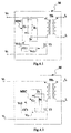
- Figure 3.1 shows a possible implementation of the DC/AC converter, M, that consists of a transformer TR1 which has one of its windings connected between a DC supply voltage Vi and the drain of a transistor T3 which, in turn, has its source connected to the reference voltage V0, in such a way that this transistor T3 is brought to the cut-off or switched-on state by the application of a control voltage Vc1, with a square waveform, coming from a control circuit CC1.
- a magnetising return current module MRC which is an active limiter formed by the capacitor C2 in series with the drain-source junction of the transistor T4, the latter operating in the cut-off or switched-on state through the application to its gate of a control signal Vc2 coming from the control circuit CC1, this being a complementary signal to the control signal Vc1.
- This magnetising return current module MRC is connected between the node that joins the drain of the transistor T3 to one of the terminals of one of the windings of TR1 and a constant voltage node which, in this case, is the DC voltage supply Vi.
- Figure 3.2 is a variation on figure 3.1, in which the constant voltage node to which the magnetising return current module MRC is connected, is, in this case, the reference voltage V0, this module consisting of the capacitor C3 and the transistor T5, its operation being entirely analogous to the previous case.
Landscapes
- Engineering & Computer Science (AREA)
- Power Engineering (AREA)
- Rectifiers (AREA)
- Dc-Dc Converters (AREA)
- Amplifiers (AREA)
Applications Claiming Priority (3)
| Application Number | Priority Date | Filing Date | Title |
|---|---|---|---|
| ES09300668A ES2056747B1 (es) | 1993-03-31 | 1993-03-31 | Circuito de conversion de continua-continua. |
| ES9300668 | 1993-03-31 | ||
| EP94104956A EP0618666B1 (de) | 1993-03-31 | 1994-03-29 | Gleichstrom-Gleichstrom Wandlerschaltung |
Related Parent Applications (2)
| Application Number | Title | Priority Date | Filing Date |
|---|---|---|---|
| EP94104956.1 Division | 1994-03-29 | ||
| EP94104956A Division EP0618666B1 (de) | 1993-03-31 | 1994-03-29 | Gleichstrom-Gleichstrom Wandlerschaltung |
Publications (2)
| Publication Number | Publication Date |
|---|---|
| EP1071197A2 true EP1071197A2 (de) | 2001-01-24 |
| EP1071197A3 EP1071197A3 (de) | 2003-11-26 |
Family
ID=8281315
Family Applications (2)
| Application Number | Title | Priority Date | Filing Date |
|---|---|---|---|
| EP94104956A Expired - Lifetime EP0618666B1 (de) | 1993-03-31 | 1994-03-29 | Gleichstrom-Gleichstrom Wandlerschaltung |
| EP00203454A Withdrawn EP1071197A3 (de) | 1993-03-31 | 1994-03-29 | Gleichstrom -Gleichstromwandlerschaltung |
Family Applications Before (1)
| Application Number | Title | Priority Date | Filing Date |
|---|---|---|---|
| EP94104956A Expired - Lifetime EP0618666B1 (de) | 1993-03-31 | 1994-03-29 | Gleichstrom-Gleichstrom Wandlerschaltung |
Country Status (7)
| Country | Link |
|---|---|
| US (1) | US5535112A (de) |
| EP (2) | EP0618666B1 (de) |
| JP (1) | JPH06327242A (de) |
| AT (1) | ATE199112T1 (de) |
| CA (1) | CA2120286C (de) |
| DE (1) | DE69426656T2 (de) |
| ES (1) | ES2056747B1 (de) |
Cited By (3)
| Publication number | Priority date | Publication date | Assignee | Title |
|---|---|---|---|---|
| US6776856B2 (en) | 1999-07-01 | 2004-08-17 | Sollac | Aluminum-killed medium-carbon steel sheet for containers |
| CN111049262A (zh) * | 2019-11-26 | 2020-04-21 | 国网江苏省电力有限公司盐城供电分公司 | 一种基于电力物联力配网施工安全质量管控平台用传感器 |
| CN112019060A (zh) * | 2020-08-28 | 2020-12-01 | 东莞市大忠电子有限公司 | 一种车载交直流快充电源适配器电路 |
Families Citing this family (28)
| Publication number | Priority date | Publication date | Assignee | Title |
|---|---|---|---|---|
| US5303138A (en) * | 1993-04-29 | 1994-04-12 | At&T Bell Laboratories | Low loss synchronous rectifier for application to clamped-mode power converters |
| US5590032A (en) * | 1995-05-25 | 1996-12-31 | Lucent Technologies Inc. | Self-synchronized drive circuit for a synchronous rectifier in a clamped-mode power converter |
| EP0791239B1 (de) * | 1995-09-01 | 1999-05-06 | Koninklijke Philips Electronics N.V. | Leistungsversorgungseinrichtung mit verbessertem wirkungsgrad |
| JP2806320B2 (ja) * | 1995-09-13 | 1998-09-30 | 日本電気株式会社 | 同期整流回路 |
| US5694303A (en) * | 1995-11-07 | 1997-12-02 | Interpoint Corporation | Semi-regulated power supply using forward converter leakage energy |
| US5619402A (en) * | 1996-04-16 | 1997-04-08 | O2 Micro, Inc. | Higher-efficiency cold-cathode fluorescent lamp power supply |
| WO1997040679A1 (en) | 1996-05-01 | 1997-11-06 | Imarx Pharmaceutical Corp. | Methods for delivering compounds into a cell |
| GB2313495B (en) * | 1996-05-20 | 2000-11-01 | Int Rectifier Corp | Synchronizing/driving circuit for a forward synchronous rectifier |
| US5757173A (en) * | 1996-10-31 | 1998-05-26 | Linfinity Microelectronics, Inc. | Semi-soft switching and precedent switching in synchronous power supply controllers |
| US7269034B2 (en) | 1997-01-24 | 2007-09-11 | Synqor, Inc. | High efficiency power converter |
| EP0954899A2 (de) | 1997-01-24 | 1999-11-10 | Fische, LLC | Hocheffizienter stromrichter |
| US6011703A (en) * | 1997-07-30 | 2000-01-04 | Lucent Technologies Inc. | Self-synchronized gate drive for power converter employing self-driven synchronous rectifier and method of operation thereof |
| DE69822284T2 (de) * | 1997-08-04 | 2005-02-24 | Koninklijke Philips Electronics N.V. | Stromversorgung mit syncronischer gleichrichtung |
| US6081432A (en) * | 1998-05-26 | 2000-06-27 | Artesyn Technologies, Inc. | Active reset forward converter employing synchronous rectifiers |
| EP1001514A3 (de) * | 1998-11-16 | 2000-09-27 | Alcatel | Schaltstromwandler mit Uberbrückungszeit und Oberwellenreduzierung |
| US6246592B1 (en) | 1999-08-10 | 2001-06-12 | Texas Instruments Incorporated | Unique power supply architecture with cascaded converters for large input-to-output step-down ratio |
| JP3233138B2 (ja) * | 1999-09-27 | 2001-11-26 | 松下電器産業株式会社 | インバータ回路 |
| GB2370655B (en) * | 2000-07-18 | 2005-01-19 | Coutant Lambda Ltd | A DC switching regulator |
| SE520159C2 (sv) * | 2001-01-26 | 2003-06-03 | Ericsson Telefon Ab L M | Anordning för avmagnetisering av en transformator |
| JP4088756B2 (ja) * | 2001-03-13 | 2008-05-21 | デンセイ・ラムダ株式会社 | スイッチング電源装置 |
| EP1388208B1 (de) * | 2001-03-28 | 2007-01-10 | Koninklijke Philips Electronics N.V. | Sychrongleichrichter |
| US6545883B2 (en) | 2001-05-07 | 2003-04-08 | Artesyn Technologies, Inc. | Integrated boost-asymmetrical half-bridge converter |
| US6421256B1 (en) * | 2001-06-25 | 2002-07-16 | Koninklijke Philips Electronics N.V. | Method for reducing mains harmonics and switching losses in discontinuous-mode, switching power converters |
| US7049767B2 (en) * | 2003-03-24 | 2006-05-23 | International Rectifier Corporation | High voltage offset detection circuit and method |
| EP1551097A1 (de) * | 2003-12-31 | 2005-07-06 | STMicroelectronics S.r.l. | Stromrichteranordnung mit einer Ansteuerung für Synchrongleichrichter und einer Begrenzung von Spannungsschwingungen während des lückenden Betriebes |
| JP5157987B2 (ja) * | 2009-03-25 | 2013-03-06 | 株式会社豊田自動織機 | 絶縁形dc−dcコンバータ |
| ATE523948T1 (de) * | 2009-04-07 | 2011-09-15 | Osram Gmbh | Wandlungsvorrichtung und entsprechendes wandlungsverfahren |
| US10199950B1 (en) | 2013-07-02 | 2019-02-05 | Vlt, Inc. | Power distribution architecture with series-connected bus converter |
Family Cites Families (7)
| Publication number | Priority date | Publication date | Assignee | Title |
|---|---|---|---|---|
| US4441146A (en) * | 1982-02-04 | 1984-04-03 | Vicor Corporation | Optimal resetting of the transformer's core in single ended forward converters |
| US4809148A (en) * | 1987-10-21 | 1989-02-28 | British Columbia Telephone Company | Full-fluxed, single-ended DC converter |
| US4951186A (en) * | 1988-03-04 | 1990-08-21 | Siemens Aktiengesellschaft | Single-ended forward frequency converter with a transformer and a demagnetization means |
| ES2051950T3 (es) * | 1989-09-29 | 1994-07-01 | Siemens Ag | Disposicion de circuito para una fuente de alimentacion de conexion de transformador de bloqueo. |
| DE3942593A1 (de) * | 1989-12-22 | 1991-06-27 | Bosch Gmbh Robert | Einrichtung zur energieversorgung einer heizscheibe aus dem fahrzeugbordnetz |
| US5126931A (en) * | 1990-09-07 | 1992-06-30 | Itt Corporation | Fixed frequency single ended forward converter switching at zero voltage |
| US5434768A (en) * | 1993-02-12 | 1995-07-18 | Rompower | Fixed frequency converter switching at zero voltage |
-
1993
- 1993-03-31 ES ES09300668A patent/ES2056747B1/es not_active Expired - Fee Related
-
1994
- 1994-03-29 DE DE69426656T patent/DE69426656T2/de not_active Expired - Lifetime
- 1994-03-29 EP EP94104956A patent/EP0618666B1/de not_active Expired - Lifetime
- 1994-03-29 EP EP00203454A patent/EP1071197A3/de not_active Withdrawn
- 1994-03-29 AT AT94104956T patent/ATE199112T1/de active
- 1994-03-30 US US08/220,018 patent/US5535112A/en not_active Expired - Lifetime
- 1994-03-30 CA CA002120286A patent/CA2120286C/en not_active Expired - Lifetime
- 1994-03-31 JP JP6062854A patent/JPH06327242A/ja active Pending
Cited By (3)
| Publication number | Priority date | Publication date | Assignee | Title |
|---|---|---|---|---|
| US6776856B2 (en) | 1999-07-01 | 2004-08-17 | Sollac | Aluminum-killed medium-carbon steel sheet for containers |
| CN111049262A (zh) * | 2019-11-26 | 2020-04-21 | 国网江苏省电力有限公司盐城供电分公司 | 一种基于电力物联力配网施工安全质量管控平台用传感器 |
| CN112019060A (zh) * | 2020-08-28 | 2020-12-01 | 东莞市大忠电子有限公司 | 一种车载交直流快充电源适配器电路 |
Also Published As
| Publication number | Publication date |
|---|---|
| EP0618666B1 (de) | 2001-02-07 |
| ES2056747B1 (es) | 1997-10-16 |
| DE69426656D1 (de) | 2001-03-15 |
| ES2056747R (de) | 1997-03-01 |
| ATE199112T1 (de) | 2001-02-15 |
| EP0618666A3 (de) | 1995-01-04 |
| JPH06327242A (ja) | 1994-11-25 |
| CA2120286A1 (en) | 1994-10-01 |
| EP1071197A3 (de) | 2003-11-26 |
| US5535112A (en) | 1996-07-09 |
| DE69426656T2 (de) | 2001-09-20 |
| EP0618666A2 (de) | 1994-10-05 |
| ES2056747A2 (es) | 1994-10-01 |
| CA2120286C (en) | 1998-02-17 |
Similar Documents
| Publication | Publication Date | Title |
|---|---|---|
| US5535112A (en) | DC/DC conversion circuit | |
| US6038148A (en) | Self-driven synchronous rectification scheme | |
| US6831847B2 (en) | Synchronous rectifier drive circuit and power supply including same | |
| USRE37510E1 (en) | Self-synchronized drive circuit for a synchronized rectifier in a clamped-mode power converter | |
| JP4515683B2 (ja) | 同期整流の外部駆動方式 | |
| US6538905B2 (en) | DC-to-DC power converter including at least two cascaded power conversion stages | |
| US5726869A (en) | Synchronous rectifier type DC-to-DC converter in which a saturable inductive device is connected in series with a secondary-side switching device | |
| US6288920B1 (en) | Drive compensation circuit for synchronous rectifier and method of operating the same | |
| US9118259B2 (en) | Phase-shifted dual-bridge DC/DC converter with wide-range ZVS and zero circulating current | |
| US5343383A (en) | Rectifier for DC/DC converter | |
| KR100691929B1 (ko) | 플로팅 게이트를 가진 동기 정류기에 대한 일반적인 자기 구동 동기 정류 방식 | |
| US6570268B1 (en) | Synchronous rectifier drive circuit and power supply including same | |
| EP1120896A2 (de) | Resonanter Leistungsumwandler | |
| US20020167821A1 (en) | Integrated boost-asymmetrical half-bridge converter | |
| US11641165B2 (en) | Flyback converter and method of operating the same | |
| US6650551B1 (en) | ZVS/ZVT resonant choke with voltage clamp winding | |
| US20180351469A1 (en) | Multi-transformer llc resonant converter circuit | |
| US6597587B1 (en) | Current driven synchronous rectifier with energy recovery using hysterisis driver | |
| KR100874809B1 (ko) | 영전압-영전류 스위칭을 이용한 3레벨 직류-직류 컨버터 | |
| US11632051B2 (en) | Flyback converter and method of operating the same | |
| KR102075470B1 (ko) | 플라이백 컨버터 | |
| KR100842734B1 (ko) | 영전압-영전류 스위칭을 이용한 3레벨 직류-직류 컨버터 | |
| KR102537358B1 (ko) | 절연형 스위칭 전원 | |
| KR100353803B1 (ko) | 직류 전압 변환기 | |
| JPH05344718A (ja) | 電力変換装置の駆動回路 |
Legal Events
| Date | Code | Title | Description |
|---|---|---|---|
| PUAI | Public reference made under article 153(3) epc to a published international application that has entered the european phase |
Free format text: ORIGINAL CODE: 0009012 |
|
| AC | Divisional application: reference to earlier application |
Ref document number: 618666 Country of ref document: EP |
|
| AK | Designated contracting states |
Kind code of ref document: A2 Designated state(s): AT BE CH DE FR GB IE IT LI SE |
|
| RIN1 | Information on inventor provided before grant (corrected) |
Inventor name: RODRIGUEZ PEREZ, JULIO Inventor name: DE LA CRUZ MORENO, ENRIQUE Inventor name: VAZQUEZ LOPEZ, MANUEL |
|
| RIN1 | Information on inventor provided before grant (corrected) |
Inventor name: RODRIGUEZ PEREZ, JULIO Inventor name: DE LA CRUZ MORENO, ENRIQUE Inventor name: VAZQUEZ LOPEZ, MANUEL |
|
| PUAL | Search report despatched |
Free format text: ORIGINAL CODE: 0009013 |
|
| AK | Designated contracting states |
Kind code of ref document: A3 Designated state(s): AT BE CH DE FR GB IE IT LI SE |
|
| 17P | Request for examination filed |
Effective date: 20040526 |
|
| AKX | Designation fees paid |
Designated state(s): AT BE CH DE FR GB IE IT LI SE |
|
| RAP1 | Party data changed (applicant data changed or rights of an application transferred) |
Owner name: ALCATEL LUCENT |
|
| STAA | Information on the status of an ep patent application or granted ep patent |
Free format text: STATUS: THE APPLICATION IS DEEMED TO BE WITHDRAWN |
|
| 18D | Application deemed to be withdrawn |
Effective date: 20080917 |