EP1071285A1 - Compensation verticale dans une caméra en mouvement - Google Patents
Compensation verticale dans une caméra en mouvement Download PDFInfo
- Publication number
- EP1071285A1 EP1071285A1 EP99401815A EP99401815A EP1071285A1 EP 1071285 A1 EP1071285 A1 EP 1071285A1 EP 99401815 A EP99401815 A EP 99401815A EP 99401815 A EP99401815 A EP 99401815A EP 1071285 A1 EP1071285 A1 EP 1071285A1
- Authority
- EP
- European Patent Office
- Prior art keywords
- image
- frame
- camera
- frames
- display
- Prior art date
- Legal status (The legal status is an assumption and is not a legal conclusion. Google has not performed a legal analysis and makes no representation as to the accuracy of the status listed.)
- Withdrawn
Links
- 238000012545 processing Methods 0.000 claims abstract description 33
- 230000003287 optical effect Effects 0.000 claims abstract description 17
- 238000000034 method Methods 0.000 claims abstract description 15
- 238000004891 communication Methods 0.000 claims description 15
- 230000009466 transformation Effects 0.000 claims description 14
- 238000004458 analytical method Methods 0.000 claims description 10
- 238000005259 measurement Methods 0.000 claims description 4
- 238000000844 transformation Methods 0.000 claims description 2
- 238000003672 processing method Methods 0.000 claims 1
- 238000012937 correction Methods 0.000 description 6
- 238000010586 diagram Methods 0.000 description 6
- 230000005540 biological transmission Effects 0.000 description 4
- 230000003139 buffering effect Effects 0.000 description 2
- 230000006870 function Effects 0.000 description 2
- 238000013459 approach Methods 0.000 description 1
- 238000013461 design Methods 0.000 description 1
- 230000000694 effects Effects 0.000 description 1
- 238000011156 evaluation Methods 0.000 description 1
- 230000005484 gravity Effects 0.000 description 1
- 230000001788 irregular Effects 0.000 description 1
- 239000013307 optical fiber Substances 0.000 description 1
- 230000008447 perception Effects 0.000 description 1
- 230000035484 reaction time Effects 0.000 description 1
- 239000007787 solid Substances 0.000 description 1
- 230000000007 visual effect Effects 0.000 description 1
- 238000004804 winding Methods 0.000 description 1
Images


Classifications
-
- H—ELECTRICITY
- H04—ELECTRIC COMMUNICATION TECHNIQUE
- H04N—PICTORIAL COMMUNICATION, e.g. TELEVISION
- H04N7/00—Television systems
- H04N7/14—Systems for two-way working
- H04N7/141—Systems for two-way working between two video terminals, e.g. videophone
- H04N7/142—Constructional details of the terminal equipment, e.g. arrangements of the camera and the display
-
- H—ELECTRICITY
- H04—ELECTRIC COMMUNICATION TECHNIQUE
- H04N—PICTORIAL COMMUNICATION, e.g. TELEVISION
- H04N23/00—Cameras or camera modules comprising electronic image sensors; Control thereof
- H04N23/60—Control of cameras or camera modules
- H04N23/63—Control of cameras or camera modules by using electronic viewfinders
-
- H—ELECTRICITY
- H04—ELECTRIC COMMUNICATION TECHNIQUE
- H04N—PICTORIAL COMMUNICATION, e.g. TELEVISION
- H04N7/00—Television systems
- H04N7/14—Systems for two-way working
- H04N7/141—Systems for two-way working between two video terminals, e.g. videophone
- H04N7/142—Constructional details of the terminal equipment, e.g. arrangements of the camera and the display
- H04N2007/145—Handheld terminals
Definitions
- the invention relates to image processing, more especially to a method of and apparatus for processing motion picture images taken with a moving camera such as a hand-held camera, or a hand-held terminal device including a camera.
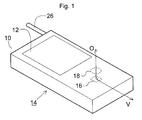
- FIG. 1 of the accompanying drawings illustrates one possible design for a video telephone in the form of a hand-held terminal 14.
- the hand-held terminal has a main housing 10 to which is mounted a video display 12 and an antenna 26.
- the display is provided for showing moving picture images received by the terminal from a wireless transmission to the antenna 26.
- a camera 16 and 18 for taking images is built into the housing 10.
- the camera is provided to take a sequence of image frames and to supply them to the antenna 26 for wireless transmission to a base station.
- the camera will most likely be a digital camera based on a charged coupled device (CCD) 16, or other array detector, and will have conventional lens optics 18, possibly in conjunction with optical fibre components.
- the camera will have an optical axis "O".
- CCD charged coupled device
- V vertical alignment of the terminal
- the alignment of the display 12 will be made to coincide with the alignment of the projection of the image viewed by the camera on the rectangular active area of the CCD chip 16.
- the antenna 26 may be a broad-band transceiver antenna 26, or some other antenna arrangement such as separate helical antennae for receiving and transmitting arranged within the housing 10.
- the main housing 10 will also comprise various keys or buttons for dialling and other functions, and have an in-built loudspeaker and microphone for the audio part of the signal. These components are not shown.
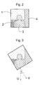
- FIG. 2 of the accompanying drawings illustrates Janet's image displayed on John's hand-held terminal with proper alignment of Janet's hand-held terminal relative to herself.
- the image is shown as a number of shaded objects, as would result from use of a standard such as MPEG-4.
- Janet is object 3, the remaining objects 1, 2 and 4 being background objects.
- FIG. 3 of the accompanying drawings shows Janet's image as superimposed on the CCD chip 16 of her hand-held terminal, which is now being held by her tilted at an angle. More particularly, the vertical axis "V" of the hand-held terminal now extends at an angle ⁇ to an axis "U” characteristic of Janet's image.
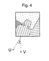
- Figure 4 of the accompanying drawings shows Janet's image as it appears on the display of John's hand-held terminal when Janet is holding her terminal as shown in Figure 3.
- John could re-align Janet's image by rotating his terminal, but this would affect his image as displayed on Janet's terminal. Reaction times and transmission lag could result in an unstable picture orientation if communicating parties attempt hand correction of the vertical alignment in this way.
- the image taken by the camera will appear distorted in the perception of a viewer when displayed on a remote terminal.
- a door or building will appear to be leaning over at an angle, or the horizon of a landscape will appear tilted.
- a hand-held device comprising a display for displaying moving pictures on a frame-by-frame basis and a camera having an optical axis extending generally away from the display to image a person who is viewing the display.
- the hand-held device further comprises a sensor configured to determine a rotational angle between an alignment axis of the hand-held device and a reference alignment axis in real space, and a signal processing circuit arranged to associate image frames taken by the camera with respective rotational angles determined by the sensor.
- vertical mis-alignment can be corrected for by applying a rotational transform to the image frames, either in the hand-held device itself or subsequently.
- a digital signal processor is operatively arranged between the camera's detector and an output stage of the hand-held device so as to apply a rotational transform to each image frame taken by the camera prior to supply of that frame to the output stage.
- a digital signal processor is operatively arranged between an input stage of a terminal device and its display so as to apply a rotational transform to each image frame received by the input stage prior to supply to the display, the transform being a rotation of the image frame through an angle derived from the rotational angle associated with that frame which is supplied to the hand-held device with the image data.
- the terminal device may in fact not be a hand-held device, but could be a larger device such as a bulky projector, home video player or personal computer.
- a digital signal processor for applying the rotational transform is arranged in a wireless base station used for relaying data between transceiver parties.
- the transform angle is derived from the rotational angle associated with that frame which is supplied to the base station with the image data by the transmitting party.
- an image processing apparatus comprising a digital signal processor for processing a sequence of image frames by: (a) determining a vertical alignment axis for each frame of the sequence from an analysis of the data content of that frame; (b) applying a rotational transform to each frame to map the vertical alignment axis determined by the analysis onto a fixed alignment axis of the frame; and (c) outputting the sequence of image frames.
- This approach differs from that of the first aspect of the invention in that the vertical mis-alignment is determined from image processing of the data content of the image frames themselves, rather than by an independent measurement of a physical parameter, such as gravity, with a sensor.
- the image processing apparatus of the second aspect of the invention is provided in a hand-held device comprising a camera, the image processing apparatus being connected on an output side of the camera to apply rotational transformations to frames obtained by the camera, thereby to compensate for vertical misalignment of the data content of the frames.
- the image processing apparatus of the second aspect of the invention is provided in a video display device, the image processing apparatus being connected in the data path leading to the display, thereby to compensate for vertical misalignment of the data content of the frames supplied for display.
- the display device may be a personal computer, a hand-held video telephone, or a micromirror projector, for example.
- a base station for wireless communication between a plurality of transceiver devices is equipped with an image processing apparatus according to the second aspect of the invention to compensate for vertical misalignment of the data content of the image frames received by the base station from a transmitting party prior to relaying the signal to a receiving party.
- Figure 5 illustrates a hand-held device comprising a housing 10 shaped and dimensioned to allow the device to be hand-held.
- a display 12 is secured to the housing 10 and connected internally so as to display moving pictures on a frame-by-frame basis.
- Frame data is received through the wireless antenna 26 which is a broad-band antenna. Any other standard antenna, such as a helical antenna arranged in the housing 10 could also be used.
- a camera 16 and 18 is arranged in the housing 10 so as to define an optical axis "O" extending from the housing 10 in a direction from which the display 12 is viewable by a user.
- the alignment is as shown in the drawing, with the optical axis "O" extending approximately at right angles to the plane of the display 12.
- the optical axis "O” it will be preferable to align the optical axis "O" to form an angle of close to 90° with an axis "W” extending laterally across the terminal, but the angle which the optical axis "O” forms with the notional vertical axis "V" of the terminal may be less than 90°, for example in the range 60 to 90°, to take account of a tendency to tilt the terminal slightly backwards when being held.
- the optical axis "O" is directed so as best to image a user who is holding the hand-held terminal normally to view the display 12. An image of the user will thus be incident on the array detector 16 which comprises an array of light sensitive elements for obtaining respective pixels of an image frame.
- the hand-held terminal further comprises a sensor 20 arranged in the housing 10.
- the sensor 20 is operable to determine the orientation of the hand-held terminal relative to its environment. More specifically, the sensor is configured to determine a rotational angle " ⁇ " between the vertical alignment axis "V" of the hand-held device and a reference alignment axis "U” defined by a real space orientation.
- the angle " ⁇ ” is the angle between the axes "U” and “V” in the image plane of the camera, noting that both axes by definition extend in or parallel to the image plane.
- the reference alignment axis may for example be based on sensing the earth's gravitational field axis "G", i.e. vertical.
- the axes "G” and “U” are related in that the axis "U” is the projection of axis "G” onto the image plane of the camera. A similar relation will hold between any other real-space axis defined by sensor reading and the reference axis "U” in the image plane. It is also noted that the image plane of the camera will generally be co-planar with the plane of the CCD chip 16 if conventional optics are used, and also the plane of the display 12, although this may not be the case in all applications.
- the sensor 20 may be a magneto-inductive sensor such as those used in automobile navigation systems, virtual reality head trackers and other applications.
- One commercially available sensor is made by Tri-M Systems of Canada and employs a single solenoid winding for each real-space axis, thereby to allow absolute sensing of alignment in all three dimensions. These sensors weigh only around one half of a gramme (0.02 ounces) and consume less than 1 mA of current.
- the magneto-inductive sensor can be used in combination with a digital signal processor or a dedicated signal processing circuit to compute the rotational angle " ⁇ " between the alignment axis "V" and some convenient reference alignment axis in real space, such as an axis derived from measurement of the earth's magnetic field orientation.
- an input socket 24 and an output socket 22 providing alternative routes for input and output of image data, additional to the antenna 26.
- FIG. 6 is a block diagram showing the inter-relationship between elements of the hand-held terminal illustrated in Figure 5.
- the CCD-chip 16 is arranged to read out into a first frame memory 38.
- the first frame memory 38 has the capacity to store at least one image frame at a time, preferably several image frames.
- the hand-held terminal further comprises a digital signal processor (DSP) 34 operative to apply a rotational transform to an image frame held in the first frame memory 38 and to write the transformed image frame into a second frame memory 40.
- DSP digital signal processor
- the second frame memory 40 has the capacity to store at least one image frame at a time, preferably several image frames.
- the rotational transform performs rotation of the image through an angle derived from the output of the sensor 20.
- the DSP can then refer to the look-up table using the time stamp of the image frame to be transformed.
- the CCD chip 16 is preferably oversized relative to the desired output frame. This will allow image rotation to take place within a certain angular range, for example within 20 degrees from vertical, without areas in the image plane that lie beyond edges of the active area of the CCD chip 116 being mapped onto the output frame.
- auto-enlargement techniques could be used to avoid loss of signal content at the peripheries of the output frames, with the enlargement factor being determined by the amount of rotation.
- Transformed image frames are read out from the second frame memory 40 into an output stage 42.
- the output stage 42 leads in turn to the antenna 26 through a wireless transmitter.
- Output may also take place through an electrical or optical communication line 21 leading to the output socket 22.
- One method by which the rotational transform can be performed is to calculate a new pixel address using the coordinates of the corners of a triangle where the sides that are separated by the mis-alignment angle ⁇ are of equal length.
- the coordinates of the corners of the triangles opposite to the angle ⁇ represent the old and new coordinates for the pixel concerned.
- This relocation of pixels is repeated pixel by pixel over the frames to be corrected with the new pixel addresses being written into the second frame memory 40 and the old pixel addresses being read from the first frame memory 38.
- rotational transform can be performed based on block transformation of visual or audio-visual objects in an encoded video signal, such as in MPEG-4.
- MPEG-4 tools, algorithms and profiles can be developed and defined which allow for rotational transformation on a frame-by-frame basis.
- rotational transformation could be confined to the audio-visual object or objects forming the subject person, with a synthetic background being substituted for the real background.
- Figure 6 also shows in dotted lines a drive 44 connected to the communication line 21 from the output stage 42.
- the drive 44 is mounted in the housing 10 and includes a removable data carrier 46.
- the removable data carrier could be a digital audio tape or optical disc.
- the sequence of images stored on the data carrier 46 could also be viewable on the display 12 through a playing function of the hand-held terminal.
- the data carrier 46 could be a fixed data carrier such as a memory, e.g. a non-volatile solid state memory, and the drive 44 could be omitted. If a data carrier of this kind were included, a sequence of images taken by the camera could be stored in the hand-held terminal for later read out through the output 22.
- the display 12 could be omitted altogether, as could the wireless components such as the wireless transmitter and antenna 26.
- FIG. 7 is a flow diagram showing operation of the DSP 34 to compensate for vertical mis-alignment of the data content of the image frames.
- the DSP 34 is configured to process the frames taken by the CCD chip 16 by determining a vertical alignment axis for each frame of the sequence.
- a rotational transform is then applied to rotate each frame through an angle determined from the mis-alignment between the axis "V" and the axis "U", as defined by the real vertical axis "G” as projected onto the image plane of the camera.
- the thus transformed image frames are then output in sequence to the frame memory 40 and on to the output stage 42.
- the correction angle is thus determined responsive to reference data of axial camera alignment in real space obtained contemporaneously with the frame concerned.
- the senor 20 is omitted.
- the digital signal processor is then configured to apply standard image processing techniques to compute the vertical alignment axis "U" of each frame.
- the mis-alignment angle is thus determined from an analysis of the image content of the frames themselves.
- One technique is to identify mutually perpendicular straight lines between data objects in the image. These can then be classified into vertical and horizontal lines from which the alignment axis "U" can be deduced. Referring to the image shown in Figure 2, such lines appear at the border between data objects 1 & 2, and 1 & 4.
- An advantage of this technique is that the orientation of objects can be identified using contrast techniques to isolate the boundaries of the object. If an object is irregular in shape the DSP can be configured so as to perform no alignment correction. For example, a sequence of images of a dropping flower can be processed by making no alignment correction, since no straight alignment lines are identified.
- vertical mis-alignment in the image frames taken by a moving camera can be corrected for prior to output, either using a reference axis obtained from sensor data collated from a sensor mounted in fixed relation to the camera, or through an image processing analysis of the data content of the image frames.
- a further alternative is instead to defer rotational transformation of the image frames until immediately prior to supply to the display 12. This alternative is now described with reference to Figure 8.
- Figure 8 illustrates internal structure of a hand-held terminal as shown in Figure 5.
- Image frames are received in sequence at the antenna 26, or from the input socket 24 through the electrical or optical communication line 21.
- the input stage 30 supplies the image data into a first frame memory 32.
- the image data not only includes the pixel data but also includes a rotational angle which is the angle taken by the sensor 20 in the transmitting device.
- a DSP 34 is then arranged to apply a rotational transform to its image frame prior to supply to the display.
- the DSP 34 reads the rotational angle ⁇ for an image frame from the frame memory 32 and then applies the transform rotating through that angle ⁇ on the pixel data for that frame which is then read from the first frame memory 32 and, after transformation, written to the second frame memory 36 from which the image data corrected for vertical mis-alignment is supplied to the display 12.
- the DSP 34 determines the rotational angle itself from an analysis of the image content of the frames held in the first frame memory 32, in which case no rotational angle needs to be supplied with the signal input from the antenna 26 or input socket 24.
- This variant will be understood by analogy to the above-described variant of Figure 6 in which the sensor 20 is dispensed with.
- Figure 9 shows a further embodiment of the invention in the form of a base station 50 comprising a receiver 52, image processor 54 and transmitter 56.
- the base station is of the kind provided for relaying wireless communications between transceiver devices such as hand-held video telephones.
- the receiver 52 and transmitter 56 are conventional components, but the image processing apparatus 54 is operable to perform automatic correction for vertical mis-alignment in the image frames.
- the image processing apparatus 54 includes a digital signal processor operable to determine a vertical alignment axis for each frame of the video sequence from an analysis of the data content of that frame, as described further above with reference to the preceding embodiments. A rotational transform is applied to each frame to map the vertical alignment axis determined by the analysis on to a fixed alignment axis for that frame.
- the frames, transformed to compensate for vertical mis-alignment of the data content, are then output to the transmitter 56.
- this embodiment there is the advantage that standard hand-held terminal devices can be used, since the image processing is performed centrally at the base station. Terminal equipment costs can therefore be reduced and more numerically intensive image processing techniques can be used, since a larger computing resource can be employed in the base station than is possible in the terminal devices.
- FIG. 9 may depict an image processing apparatus as described with reference to Figure 9 in any apparatus used to record, display or process sequences of image frames, thereby to compensate for vertical mis-alignment of image content prior to transmission, recording or display of a sequence of image frames.
- One example of a display apparatus is a video player, which may additionally have a recording capability and thus be a combined display and recording apparatus.
- a recording apparatus is a semi-professional or professional type video camera.
- a professional cameraman achieves vertical alignment manually by looking through the viewfinder.
- picture orientation is maintained by a mechanical gyroscope system held by the cameraman in which the video camera is suspended.
- a video camera could be provided with an image processing apparatus as described with reference to Figure 9 which serves to analyze and correct the vertical alignment only within a relatively small angular range, for example up to five degrees from vertical, based on the assumption that approximate vertical alignment will have already been achieved manually by the cameraman.
- the alignment correction could be activated over a larger range of angles and the mechanical gyroscope support dispensed with.
Landscapes
- Engineering & Computer Science (AREA)
- Multimedia (AREA)
- Signal Processing (AREA)
- Studio Devices (AREA)
Priority Applications (3)
| Application Number | Priority Date | Filing Date | Title |
|---|---|---|---|
| EP99401815A EP1071285A1 (fr) | 1999-07-19 | 1999-07-19 | Compensation verticale dans une caméra en mouvement |
| US09/615,117 US6781623B1 (en) | 1999-07-19 | 2000-07-13 | Vertical compensation in a moving camera |
| US10/889,954 US20040252200A1 (en) | 1999-07-19 | 2004-07-13 | Vertical compensation in a moving camera |
Applications Claiming Priority (1)
| Application Number | Priority Date | Filing Date | Title |
|---|---|---|---|
| EP99401815A EP1071285A1 (fr) | 1999-07-19 | 1999-07-19 | Compensation verticale dans une caméra en mouvement |
Publications (1)
| Publication Number | Publication Date |
|---|---|
| EP1071285A1 true EP1071285A1 (fr) | 2001-01-24 |
Family
ID=8242065
Family Applications (1)
| Application Number | Title | Priority Date | Filing Date |
|---|---|---|---|
| EP99401815A Withdrawn EP1071285A1 (fr) | 1999-07-19 | 1999-07-19 | Compensation verticale dans une caméra en mouvement |
Country Status (2)
| Country | Link |
|---|---|
| US (2) | US6781623B1 (fr) |
| EP (1) | EP1071285A1 (fr) |
Cited By (7)
| Publication number | Priority date | Publication date | Assignee | Title |
|---|---|---|---|---|
| EP1298925A3 (fr) * | 2001-09-28 | 2004-04-07 | Matsushita Electric Industrial Co., Ltd. | Méthode et appareil de communication d'images animées |
| WO2004066615A1 (fr) * | 2003-01-22 | 2004-08-05 | Nokia Corporation | Commande d'images |
| WO2006007315A3 (fr) * | 2004-06-22 | 2006-05-04 | Analog Devices Inc | Systeme et procede destines au traitement d'une image de camera numerique |
| WO2008061811A1 (fr) * | 2006-11-24 | 2008-05-29 | Sony Ericsson Mobile Communications Ab | Alignement d'une image dans un dispositif d'imagerie portable |
| US7567752B2 (en) | 2006-11-24 | 2009-07-28 | Sony Ericsson Mobile Communications Ab | Image alignment system with overlying frame in display |
| WO2013188310A1 (fr) * | 2012-06-14 | 2013-12-19 | Qualcomm Incorporated | Estimation adaptative de la latence d'un marqueur temporel de trame |
| WO2014031830A1 (fr) * | 2012-08-23 | 2014-02-27 | Smugmug, Inc. | Stabilisation de rotation |
Families Citing this family (46)
| Publication number | Priority date | Publication date | Assignee | Title |
|---|---|---|---|---|
| US6901429B2 (en) * | 2000-10-27 | 2005-05-31 | Eric Morgan Dowling | Negotiated wireless peripheral security systems |
| US7035932B1 (en) | 2000-10-27 | 2006-04-25 | Eric Morgan Dowling | Federated multiprotocol communication |
| US7742073B1 (en) * | 2000-11-01 | 2010-06-22 | Koninklijke Philips Electronics N.V. | Method and apparatus for tracking an object of interest using a camera associated with a hand-held processing device |
| US20030076408A1 (en) * | 2001-10-18 | 2003-04-24 | Nokia Corporation | Method and handheld device for obtaining an image of an object by combining a plurality of images |
| WO2004008411A1 (fr) * | 2002-07-11 | 2004-01-22 | Nokia Corporation | Procede et dispositif de modification automatique d'un contenu numerique dans un dispositif mobile conformement au donnees de capteur |
| WO2004047011A2 (fr) * | 2002-11-20 | 2004-06-03 | Koninklijke Philips Electronics N.V. | Systeme d'interface utilisateur fonde sur un dispositif de pointage |
| US20040100560A1 (en) * | 2002-11-22 | 2004-05-27 | Stavely Donald J. | Tracking digital zoom in a digital video camera |
| US20050093891A1 (en) * | 2003-11-04 | 2005-05-05 | Pixel Instruments Corporation | Image orientation apparatus and method |
| WO2005093654A2 (fr) | 2004-03-25 | 2005-10-06 | Fatih Ozluturk | Procede et appareil de correction du flot des images numeriques en raison du mouvement du sujet ou du dispositif d'imagerie |
| US10721405B2 (en) | 2004-03-25 | 2020-07-21 | Clear Imaging Research, Llc | Method and apparatus for implementing a digital graduated filter for an imaging apparatus |
| US9826159B2 (en) | 2004-03-25 | 2017-11-21 | Clear Imaging Research, Llc | Method and apparatus for implementing a digital graduated filter for an imaging apparatus |
| US8587648B2 (en) * | 2004-06-01 | 2013-11-19 | SeeScan, Inc. | Self-leveling camera head |
| KR100774479B1 (ko) * | 2004-07-06 | 2007-11-08 | 엘지전자 주식회사 | 휴대단말기의 영상신호 기울기 보정장치 및 방법 |
| US7583858B2 (en) * | 2004-10-12 | 2009-09-01 | Eastman Kodak Company | Image processing based on direction of gravity |
| US8018489B2 (en) * | 2005-02-04 | 2011-09-13 | Mccutchen David | Surveillance system |
| JP2006245726A (ja) * | 2005-03-01 | 2006-09-14 | Fuji Photo Film Co Ltd | デジタルカメラ |
| KR100708178B1 (ko) | 2005-09-01 | 2007-04-16 | 삼성전자주식회사 | 영상 처리 방법, 장치 및 영상 정보를 기록한 정보저장매체 |
| US20070081195A1 (en) * | 2005-10-07 | 2007-04-12 | Sbc Knowledge Ventures, L.P. | Digital photographic display device |
| US20070126867A1 (en) * | 2005-12-02 | 2007-06-07 | Mccutchen David | High resolution surveillance camera |
| JP5630957B2 (ja) * | 2006-05-19 | 2014-11-26 | 日産化学工業株式会社 | ハイパーブランチポリマー及びその製造方法 |
| US7593627B2 (en) | 2006-08-18 | 2009-09-22 | Sony Ericsson Mobile Communications Ab | Angle correction for camera |
| JP4068661B1 (ja) * | 2006-10-13 | 2008-03-26 | 株式会社ナビタイムジャパン | ナビゲーションシステム、携帯端末装置および経路案内方法 |
| TW200837663A (en) * | 2007-03-13 | 2008-09-16 | Univ Nat Taiwan | Constant picture quality bit rate control system for a multiple-video encoder in single video signal source and the method |
| USD584738S1 (en) * | 2007-04-12 | 2009-01-13 | Lg Electronics Inc. | MP3 player |
| USD606965S1 (en) * | 2007-09-04 | 2009-12-29 | Apple Inc. | Electronic device |
| USD598425S1 (en) | 2007-08-31 | 2009-08-18 | Apple Inc. | Electronic device |
| USD607869S1 (en) * | 2007-09-05 | 2010-01-12 | Apple Inc. | Electronic device |
| USD606966S1 (en) * | 2007-09-05 | 2009-12-29 | Apple Inc. | Electronic device |
| USD606964S1 (en) * | 2007-09-04 | 2009-12-29 | Apple Inc. | Electronic device |
| USD615554S1 (en) * | 2007-09-04 | 2010-05-11 | Apple Inc. | Electronic device |
| USD614162S1 (en) * | 2007-09-04 | 2010-04-20 | Apple Inc. | Electronic device |
| USD614161S1 (en) * | 2007-09-04 | 2010-04-20 | Apple Inc. | Electronic device |
| USD614165S1 (en) * | 2007-09-05 | 2010-04-20 | Apple Inc. | Electronic device |
| USD606967S1 (en) * | 2007-09-05 | 2009-12-29 | Apple Inc. | Electronic device |
| USD614163S1 (en) * | 2007-09-05 | 2010-04-20 | Apple Inc. | Electronic device |
| USD608763S1 (en) * | 2007-09-05 | 2010-01-26 | Apple Inc. | Electronic device |
| USD614164S1 (en) * | 2007-09-05 | 2010-04-20 | Apple Inc. | Electronic device |
| TW200917824A (en) * | 2007-10-12 | 2009-04-16 | Univ Nat Taiwan | Shockproof method for digital imaging |
| USD584743S1 (en) * | 2008-03-07 | 2009-01-13 | Sandisk Corporation | Media player |
| USD584741S1 (en) * | 2008-03-07 | 2009-01-13 | Sandisk Corporation | Media player |
| USD584740S1 (en) * | 2008-03-07 | 2009-01-13 | Sandisk Corporation | Media player |
| USD584742S1 (en) * | 2008-03-07 | 2009-01-13 | Sandisk Corporation | Media player |
| US8648919B2 (en) * | 2011-06-06 | 2014-02-11 | Apple Inc. | Methods and systems for image stabilization |
| US8823813B2 (en) | 2011-06-06 | 2014-09-02 | Apple Inc. | Correcting rolling shutter using image stabilization |
| CN104252302A (zh) * | 2013-06-26 | 2014-12-31 | 富泰华工业(深圳)有限公司 | 图像自适应调整系统及方法 |
| WO2018072271A1 (fr) * | 2016-10-17 | 2018-04-26 | 华为技术有限公司 | Procédé et dispositif d'optimisation d'affichage d'image |
Citations (8)
| Publication number | Priority date | Publication date | Assignee | Title |
|---|---|---|---|---|
| EP0456414A2 (fr) * | 1990-05-11 | 1991-11-13 | Matsushita Electric Industrial Co., Ltd. | Correction de l'inclinaison pour un appareil de caméra vidéo |
| WO1991018366A1 (fr) * | 1990-05-21 | 1991-11-28 | Eastman Kodak Company | Procede de detection de desalignement dans des images de feuillet |
| EP0526802A2 (fr) * | 1991-08-07 | 1993-02-10 | Alcatel SEL Aktiengesellschaft | Radiotéléphone |
| GB2307133A (en) * | 1995-11-13 | 1997-05-14 | Secr Defence | Video camera image stabilisation system |
| DE19720200A1 (de) * | 1996-05-14 | 1997-11-20 | Sony Corp | Bildaufnahmevorrichtung |
| DE19726602A1 (de) * | 1996-07-10 | 1998-01-29 | Motorola Inc | Kommunikationsvorrichtung |
| EP0884905A2 (fr) * | 1997-06-13 | 1998-12-16 | Nokia Mobile Phones Ltd. | Méthode et appareil de traitement d'une image pour la transmission d'un terminal |
| US5910815A (en) * | 1994-09-13 | 1999-06-08 | U.S. Philips Corporation | Telephone set |
Family Cites Families (18)
| Publication number | Priority date | Publication date | Assignee | Title |
|---|---|---|---|---|
| JPS58222382A (ja) * | 1982-06-18 | 1983-12-24 | Ricoh Co Ltd | 画像の傾き補正方式 |
| JP2829006B2 (ja) * | 1988-11-10 | 1998-11-25 | 株式会社リコー | 画像処理装置 |
| US5060074A (en) * | 1989-10-18 | 1991-10-22 | Hitachi, Ltd. | Video imaging apparatus |
| JP2891342B2 (ja) * | 1992-03-09 | 1999-05-17 | 富士ゼロックス株式会社 | 画像信号処理装置 |
| US5335290A (en) * | 1992-04-06 | 1994-08-02 | Ricoh Corporation | Segmentation of text, picture and lines of a document image |
| US5825415A (en) * | 1993-12-17 | 1998-10-20 | Canon Kabushiki Kaisha | Electronic image-movement correcting device with a variable correction step feature |
| JPH08336069A (ja) * | 1995-04-13 | 1996-12-17 | Eastman Kodak Co | 電子スチルカメラ |
| US5973733A (en) * | 1995-05-31 | 1999-10-26 | Texas Instruments Incorporated | Video stabilization system and method |
| US5926221A (en) * | 1995-08-18 | 1999-07-20 | Texas Instruments Incorporated | Method and apparatus for improved video coding using a center-biased orthogonal search technique and a zero block predictor module |
| US6011585A (en) * | 1996-01-19 | 2000-01-04 | Apple Computer, Inc. | Apparatus and method for rotating the display orientation of a captured image |
| US5901253A (en) * | 1996-04-04 | 1999-05-04 | Hewlett-Packard Company | Image processing system with image cropping and skew correction |
| US6452632B1 (en) * | 1997-01-31 | 2002-09-17 | Kabushiki Kaisha Toshiba | Solid state image sensor and video system using the same |
| US6043837A (en) * | 1997-05-08 | 2000-03-28 | Be Here Corporation | Method and apparatus for electronically distributing images from a panoptic camera system |
| US6943839B1 (en) * | 1997-05-16 | 2005-09-13 | Canon Kabushiki Kaisha | Photographic method at time of self-photography, and image sensing apparatus thereof |
| US6535243B1 (en) * | 1998-01-06 | 2003-03-18 | Hewlett- Packard Company | Wireless hand-held digital camera |
| US6762791B1 (en) * | 1999-02-16 | 2004-07-13 | Robert W. Schuetzle | Method for processing digital images |
| FR2795206B1 (fr) * | 1999-06-17 | 2001-08-31 | Canon Kk | Procede de modification d'orientation geometrique d'une image |
| US6222584B1 (en) * | 1999-11-03 | 2001-04-24 | Inventec Corporation | Method of automatically rotating image storage data subject to image capture angle, and the related digital camera |
-
1999
- 1999-07-19 EP EP99401815A patent/EP1071285A1/fr not_active Withdrawn
-
2000
- 2000-07-13 US US09/615,117 patent/US6781623B1/en not_active Expired - Lifetime
-
2004
- 2004-07-13 US US10/889,954 patent/US20040252200A1/en not_active Abandoned
Patent Citations (8)
| Publication number | Priority date | Publication date | Assignee | Title |
|---|---|---|---|---|
| EP0456414A2 (fr) * | 1990-05-11 | 1991-11-13 | Matsushita Electric Industrial Co., Ltd. | Correction de l'inclinaison pour un appareil de caméra vidéo |
| WO1991018366A1 (fr) * | 1990-05-21 | 1991-11-28 | Eastman Kodak Company | Procede de detection de desalignement dans des images de feuillet |
| EP0526802A2 (fr) * | 1991-08-07 | 1993-02-10 | Alcatel SEL Aktiengesellschaft | Radiotéléphone |
| US5910815A (en) * | 1994-09-13 | 1999-06-08 | U.S. Philips Corporation | Telephone set |
| GB2307133A (en) * | 1995-11-13 | 1997-05-14 | Secr Defence | Video camera image stabilisation system |
| DE19720200A1 (de) * | 1996-05-14 | 1997-11-20 | Sony Corp | Bildaufnahmevorrichtung |
| DE19726602A1 (de) * | 1996-07-10 | 1998-01-29 | Motorola Inc | Kommunikationsvorrichtung |
| EP0884905A2 (fr) * | 1997-06-13 | 1998-12-16 | Nokia Mobile Phones Ltd. | Méthode et appareil de traitement d'une image pour la transmission d'un terminal |
Non-Patent Citations (3)
| Title |
|---|
| DATABASE INSPEC [online] THE INSTITUTION OF ELECTRICAL ENGINEERS, STEVENAGE, GB; 1996, GUTTAG K.: "The TMS3208x family architecture and future roadmap", Database accession no. 5413437 * |
| DIGITAL SIGNAL PROCESSING TECHNOLOGY 10-11 APRIL 1996 ORLANDO, FL, USA, vol. 2750, PROCEEDINGS OF THE SPIE - THE INTERNATIONAL SOCIETY FOR OPTICAL ENGINEERING SPIE-INT. SOC. OPT. ENG USA, pages 2 - 11, ISSN: 0277-786X * |
| KNEIP J. ET AL: "Memory efficient list based Hough transform for programmable digital signal processors with on-chip caches", CONFERENCE PROCEEDINGS ARTICLE, 1 September 1996 (1996-09-01), pages 191 - 194, XP010199649 * |
Cited By (11)
| Publication number | Priority date | Publication date | Assignee | Title |
|---|---|---|---|---|
| EP1298925A3 (fr) * | 2001-09-28 | 2004-04-07 | Matsushita Electric Industrial Co., Ltd. | Méthode et appareil de communication d'images animées |
| US6833857B2 (en) | 2001-09-28 | 2004-12-21 | Matsushita Electric Industrial Co., Ltd. | Moving picture communication method and apparatus |
| WO2004066615A1 (fr) * | 2003-01-22 | 2004-08-05 | Nokia Corporation | Commande d'images |
| WO2006007315A3 (fr) * | 2004-06-22 | 2006-05-04 | Analog Devices Inc | Systeme et procede destines au traitement d'une image de camera numerique |
| WO2008061811A1 (fr) * | 2006-11-24 | 2008-05-29 | Sony Ericsson Mobile Communications Ab | Alignement d'une image dans un dispositif d'imagerie portable |
| US7567752B2 (en) | 2006-11-24 | 2009-07-28 | Sony Ericsson Mobile Communications Ab | Image alignment system with overlying frame in display |
| WO2013188310A1 (fr) * | 2012-06-14 | 2013-12-19 | Qualcomm Incorporated | Estimation adaptative de la latence d'un marqueur temporel de trame |
| US9116001B2 (en) | 2012-06-14 | 2015-08-25 | Qualcomm Incorporated | Adaptive estimation of frame time stamp latency |
| WO2014031830A1 (fr) * | 2012-08-23 | 2014-02-27 | Smugmug, Inc. | Stabilisation de rotation |
| US9843729B2 (en) | 2012-08-23 | 2017-12-12 | Smugmug, Inc. | Rotation stabilization |
| US9998667B2 (en) | 2012-08-23 | 2018-06-12 | Smugmug, Inc. | Rotation stabilization |
Also Published As
| Publication number | Publication date |
|---|---|
| US20040252200A1 (en) | 2004-12-16 |
| US6781623B1 (en) | 2004-08-24 |
Similar Documents
| Publication | Publication Date | Title |
|---|---|---|
| US6781623B1 (en) | Vertical compensation in a moving camera | |
| US11785344B2 (en) | Panoramic camera | |
| US20210084221A1 (en) | Image processing system and image processing method | |
| US6542184B1 (en) | Methods, apparatus, and program products for presenting panoramic images of a remote location | |
| US12549859B2 (en) | Omnidirectional camera system with improved point of interest selection | |
| EP1500045B1 (fr) | Correction de rotation d'image pour equipement video ou photographique | |
| US7224382B2 (en) | Immersive imaging system | |
| EP1178352A1 (fr) | Procédé et dispositif pour présenter des images panoramiques sur un recepteur local, et logiciel correspondant | |
| EP2132932A1 (fr) | Premier dispositif de communication portable | |
| US11102403B2 (en) | Image device, information processing apparatus, information processing method, system, and storage medium | |
| JP2002016837A (ja) | 撮像装置 | |
| JP4019785B2 (ja) | 画像表示システムと画像処理装置及び画像表示方法 | |
| US11614627B2 (en) | Image processing apparatus, head-mounted display, and image displaying method | |
| CN220570624U (zh) | 图像捕获系统和图像捕获装置 | |
| WO2020124504A1 (fr) | Procédé d'optimisation de qualité d'image, dispositif d'affichage et support | |
| US7480001B2 (en) | Digital camera with a spherical display | |
| US12477219B1 (en) | Image capture device with a non-dive mode and a dive mode | |
| JPH1169280A (ja) | 方位情報を記録可能なスチルカメラおよび再生方法 | |
| JP2020167657A (ja) | 画像処理装置、ヘッドマウントディスプレイ、および画像表示方法 | |
| JP2000032322A (ja) | 画像捕捉システム | |
| KR20060091438A (ko) | 파노라마 전용 디지털 카메라 | |
| JP2002135373A (ja) | デジタルカメラ画像取扱方法及びこの方法に用いられる簡易デジタルカメラ並びにマルチメディア端末機 | |
| JP2007208596A (ja) | データ再生機器、データ再生方法およびプログラム | |
| JPH03139982A (ja) | 電子カメラ | |
| JPH044691A (ja) | テレビ電話用画像通信装置 |
Legal Events
| Date | Code | Title | Description |
|---|---|---|---|
| PUAI | Public reference made under article 153(3) epc to a published international application that has entered the european phase |
Free format text: ORIGINAL CODE: 0009012 |
|
| AK | Designated contracting states |
Kind code of ref document: A1 Designated state(s): AT BE CH CY DE DK ES FI FR GB GR IE IT LI LU MC NL PT SE |
|
| AX | Request for extension of the european patent |
Free format text: AL;LT;LV;MK;RO;SI |
|
| 17P | Request for examination filed |
Effective date: 20010704 |
|
| AKX | Designation fees paid |
Free format text: AT BE CH CY DE DK ES FI FR GB GR IE IT LI LU MC NL PT SE |
|
| RAP1 | Party data changed (applicant data changed or rights of an application transferred) |
Owner name: TEXAS INSTRUMENTS FRANCE Owner name: TEXAS INSTRUMENTS INC. |
|
| 17Q | First examination report despatched |
Effective date: 20060929 |
|
| STAA | Information on the status of an ep patent application or granted ep patent |
Free format text: STATUS: THE APPLICATION IS DEEMED TO BE WITHDRAWN |
|
| 18D | Application deemed to be withdrawn |
Effective date: 20100602 |