EP1071360B1 - Aspirateur comprenant un porte-accessoires - Google Patents
Aspirateur comprenant un porte-accessoires Download PDFInfo
- Publication number
- EP1071360B1 EP1071360B1 EP00901553A EP00901553A EP1071360B1 EP 1071360 B1 EP1071360 B1 EP 1071360B1 EP 00901553 A EP00901553 A EP 00901553A EP 00901553 A EP00901553 A EP 00901553A EP 1071360 B1 EP1071360 B1 EP 1071360B1
- Authority
- EP
- European Patent Office
- Prior art keywords
- handle
- holder
- vacuum cleaner
- bridge
- suction
- Prior art date
- Legal status (The legal status is an assumption and is not a legal conclusion. Google has not performed a legal analysis and makes no representation as to the accuracy of the status listed.)
- Expired - Lifetime
Links
Images


Classifications
-
- A—HUMAN NECESSITIES
- A47—FURNITURE; DOMESTIC ARTICLES OR APPLIANCES; COFFEE MILLS; SPICE MILLS; SUCTION CLEANERS IN GENERAL
- A47L—DOMESTIC WASHING OR CLEANING; SUCTION CLEANERS IN GENERAL
- A47L9/00—Details or accessories of suction cleaners, e.g. mechanical means for controlling the suction or for effecting pulsating action; Storing devices specially adapted to suction cleaners or parts thereof; Carrying-vehicles specially adapted for suction cleaners
- A47L9/0009—Storing devices ; Supports, stands or holders
- A47L9/0018—Storing devices ; Supports, stands or holders integrated in or removably mounted upon the suction cleaner for storing parts of said suction cleaner
- A47L9/0027—Storing devices ; Supports, stands or holders integrated in or removably mounted upon the suction cleaner for storing parts of said suction cleaner specially adapted for holding the suction cleaning tools
-
- A—HUMAN NECESSITIES
- A47—FURNITURE; DOMESTIC ARTICLES OR APPLIANCES; COFFEE MILLS; SPICE MILLS; SUCTION CLEANERS IN GENERAL
- A47L—DOMESTIC WASHING OR CLEANING; SUCTION CLEANERS IN GENERAL
- A47L5/00—Structural features of suction cleaners
- A47L5/12—Structural features of suction cleaners with power-driven air-pumps or air-compressors, e.g. driven by motor vehicle engine vacuum
- A47L5/22—Structural features of suction cleaners with power-driven air-pumps or air-compressors, e.g. driven by motor vehicle engine vacuum with rotary fans
- A47L5/36—Suction cleaners with hose between nozzle and casing; Suction cleaners for fixing on staircases; Suction cleaners for carrying on the back
- A47L5/362—Suction cleaners with hose between nozzle and casing; Suction cleaners for fixing on staircases; Suction cleaners for carrying on the back of the horizontal type, e.g. canister or sledge type
-
- A—HUMAN NECESSITIES
- A47—FURNITURE; DOMESTIC ARTICLES OR APPLIANCES; COFFEE MILLS; SPICE MILLS; SUCTION CLEANERS IN GENERAL
- A47L—DOMESTIC WASHING OR CLEANING; SUCTION CLEANERS IN GENERAL
- A47L9/00—Details or accessories of suction cleaners, e.g. mechanical means for controlling the suction or for effecting pulsating action; Storing devices specially adapted to suction cleaners or parts thereof; Carrying-vehicles specially adapted for suction cleaners
- A47L9/0009—Storing devices ; Supports, stands or holders
-
- A—HUMAN NECESSITIES
- A47—FURNITURE; DOMESTIC ARTICLES OR APPLIANCES; COFFEE MILLS; SPICE MILLS; SUCTION CLEANERS IN GENERAL
- A47L—DOMESTIC WASHING OR CLEANING; SUCTION CLEANERS IN GENERAL
- A47L9/00—Details or accessories of suction cleaners, e.g. mechanical means for controlling the suction or for effecting pulsating action; Storing devices specially adapted to suction cleaners or parts thereof; Carrying-vehicles specially adapted for suction cleaners
- A47L9/32—Handles
- A47L9/327—Handles for suction cleaners with hose between nozzle and casing
Definitions
- the invention relates to a vacuum cleaner comprising a housing, which accommodates a suction unit, a suction accessory, which can be coupled to the housing via a suction hose and a suction tube, a handle, which is situated near a coupling between the suction hose and the suction tube, and a holder for further accessories, which is detachably coupled to the handle and connects to said handle near a first end and a second end.
- the invention also relates to a holder which can suitably be used in a vacuum cleaner in accordance with the invention.
- the invention further relates to a suction hose which can suitably be used in a vacuum cleaner in accordance with the invention, said suction hose comprising the handle of the vacuum cleaner.
- the invention additionally relates to a suction tube which can suitably be used in a vacuum cleaner in accordance with the invention, said suction tube comprising the handle of the vacuum cleaner.
- a vacuum cleaner of the type mentioned in the opening paragraph is disclosed in EP-B-0 747 000 .
- the handle of the known vacuum cleaner is tubular and forms part of a suction duct of the vacuum cleaner which connects the suction accessory to the suction unit.
- the holder of the known vacuum cleaner is plate-shaped and extends parallel to the handle in a state wherein the holder is coupled to the handle.
- a number of further accessories of the vacuum cleaner are detachably coupled to the holder. Since the holder is in the immediate vicinity of the handle, a user of the vacuum cleaner has said accessories close at hand, resulting in a high ease of use.
- the known holder comprises, at each of the two ends, a coupling member for coupling the holder to the handle. As a result, a stable coupling of the holder to the handle is achieved.
- a drawback of the known vacuum cleaner resides in that uncoupling the holder requires both the first end and the second end of the holder to be uncoupled from the handle, while coupling the holder to the handle requires both the first end of the holder and the second end of the holder to be coupled to the handle. Consequently, coupling and uncoupling of the holder is rather inconvenient to the user.
- a further drawback of the known vacuum cleaner resides in that the forces exerted on the holder during detaching an accessory from the holder may unintentionally cause the entire holder to be uncoupled from the handle.
- the vacuum cleaner in accordance with the invention is characterized in that the holder is provided with a bridge which interconnects both ends of the holder, which holder can be coupled to the handle exclusively by means of a coupling member which is provided on a part of the bridge which is situated at a distance from both ends.
- a coupling member which is provided on a part of the bridge which is situated at a distance from both ends.
- said gripping space is situated between the holder and the bridge interconnecting both ends of the holder.
- the user gripping the handle also grips the bridge of the holder, so that, during operation, the holder cannot separate from the handle if the holder were to be unintentionally uncoupled from the handle, or if forces were to be exerted on the holder during detaching accessories from the holder.
- a particular embodiment of a vacuum cleaner in accordance with the invention is characterized in that the handle is tubular, while the bridge comprises a shell-shaped part at least near the two ends of the holder, which shell-shaped part partly fits over the tubular handle substantially without clearance.
- the bridge is provided with said shell-shaped part near both ends of the holder, the holder is secured against torsional movements about the coupling member in an effective and robust manner. It is thus precluded that, under the influence of such torsional movements, the holder is unintentionally uncoupled from the handle and that the coupling member is distorted under the influence of such torsional movements.
- a further embodiment of a vacuum cleaner in accordance with the invention is characterized in that the bridge comprises a single shell-shaped part which extends from the first end to the second end of the holder and partly fits over the tubular handle substantially without clearance. Due to the fact that the bridge comprises said single shell-shaped part, a simple construction of the holder is obtained and the handle with the bridge coupled thereto handles nicely.
- Yet another embodiment of a vacuum cleaner in accordance with the invention is characterized in that the handle and the bridge are curved, viewed in a longitudinal direction of the handle. Said curved shape of the handle and the bridge, viewed in the longitudinal direction of the handle, provides for a relatively large space between the holder and the bridge and hence a relatively large gripping space for the handle.
- a particular embodiment of a vacuum cleaner in accordance with the invention is characterized in that the handle and the bridge are provided with co-operating locking elements by means of which the holder can be locked with respect to the handle, viewed in a longitudinal direction of the handle.
- said locking elements By using said locking elements, it is precluded, in a practical and simple manner, that the holder can be moved along the handle in the longitudinal direction under the influence of handling forces when the holder is in the coupled situation.
- a further embodiment of a vacuum cleaner in accordance with the invention is characterized in that the coupling member comprises two elastically deformable hooks for co-operation with a coupling element of the handle which, viewed in cross-section, is T-shaped.
- the coupling member comprises two elastically deformable hooks for co-operation with a coupling element of the handle which, viewed in cross-section, is T-shaped.
- the coupling element comprises a central part for co-operation with the hooks of the holder, and the coupling element is provided, on either side of the central part, with parts which are widened with respect to the central part.
- the hooks and said widened parts of the coupling element form the above-mentioned co-operating locking elements by means of which shifting of the holder along the handle in the longitudinal direction is precluded. In this manner, reliably operating locking elements are obtained in a simple manner.
- the vacuum cleaner in accordance with the invention is a so-called canister-type vacuum cleaner which comprises a housing 1 which can be moved over a surface 5 to be cleaned by means of a number of wheels 3.
- the housing 1 accommodates an electrical suction unit 7 which is only diagrammatically shown in Fig. 1 .
- the vacuum cleaner further comprises a suction accessory 9 which, in the example shown, has a suction nozzle 11.
- the suction accessory 9 is detachably coupled to the housing 1 via a metal suction tube 13 and a flexible suction hose 15, said suction accessory 9 being pivotably coupled to the suction tube 13, and the suction tube 13 being detachably coupled to a tubular handle 17 secured to the suction hose 15, and the suction hose 15 being detachably coupled to an input 19 of the housing 1.
- the input 19 opens into a dust chamber 21 of the housing 1 which is connected to the suction unit 7 via a filter 23.
- the suction unit 7 creates a partial vacuum in a suction duct which comprises, in succession, the suction accessory 9, the suction tube 13, the handle 17, the suction hose 15, the input 19 and the dust chamber 21 of the vacuum cleaner. Under the influence of said partial vacuum, dust and dirt particles present on the surface 5 to be cleaned are sucked via the suction nozzle 11 of the suction accessory 9 and said suction duct towards the dust chamber 21 where they are collected in a disposable dust bag.
- the vacuum cleaner is provided with a synthetic resin holder 25 to which a number of further accessories 27, 29 of the vacuum cleaner are detachably attached, such as a number of alternative suction accessories which can be used instead of the suction accessory 9 to clean, for example, furniture.
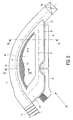
- the holder 25 is detachably coupled to the handle 17 in a manner which will be described in greater detail hereinafter, and the holder is shown in detail in Fig. 2 .
- the holder 25 comprises a clamping member 31 which extends substantially parallel to the tubular handle 17.
- Fig. 2 the holder 25 comprises a clamping member 31 which extends substantially parallel to the tubular handle 17.
- the clamping member 31 has a C-shaped cross-section with two elastically deformable cheeks 33, 35 between which the accessories 27, 29 can be clamped.
- the clamping member 31 of the holder 25 connects to the handle 17 close to a first end 37 and close to a second end 39, said two ends 37 and 39 being interconnected by a bridge 41 forming part of the holder 25.
- the bridge 41 includes a shell-shaped part 43 having a cross-section which is slightly shorter than a half ring.
- the shell-shaped part 43 extends throughout the holder 25, i.e. throughout the first end 37 of the holder 25, throughout the bridge 41 and throughout the second end 39 of the holder 25.
- the shell-shaped part 43 fits partly over the tubular handle 17, viewed throughout the length of the holder 25, both edges 45 and 47 of the shell-shaped part 43 engaging the handle 17 almost without clearance.
- a user of the vacuum cleaner has the accessories 27, 29 close at hand, so that a great ease of use is provided.
- the clamping member 31 connects with both ends 37 and 39 to the handle 17, and the two ends 37 and 39 are interconnected by the bridge 41, a large gripping space 49 is provided between the clamping member 31 and the bridge 41, in which gripping space the user can place a hand to grip the handle 17.
- the user grips the handle 17 via the gripping space 49, he is not hampered by the clamping member 31 with the further accessories 27, 29, so that said construction of the holder 25 provides a great ease of use.
- the tubular handle 17 and the bridge 41 are curved, viewed in a longitudinal direction of the handle 17, so that the gripping space 49 is further increased.
- the bridge 41 By using the bridge 41, a rigid and stable construction of the holder 25 is obtained. Since the bridge 41 comprises said shell-shaped part 43, the handle 17 and the bridge 41 handle nicely. When the user grips the handle 17, he also grips the bridge 41 of the holder 25, so that, during operation, the holder 25 cannot fall from the handle 17 if the holder 25 were to be unintentionally uncoupled from the handle 17, or if forces were to be exerted on the holder 25 during detaching the accessories 27, 29.
- the holder 25 is detachably coupled to the handle 17 exclusively by means of a coupling member 51 which is provided on a part 53 of the bridge 41 which is situated at a distance from both ends 37 and 39.
- said part 53 of the bridge 41 is closer to the second end 39 than to the first end 37.
- said part 53 of the bridge 41 may alternatively be situated centrally between the two ends 37 and 39, or closer to the first end 37 than to the second end 39.
- the coupling member 51 is situated in an enlarged part 55 of the shell-shaped part 43 of the bridge 41, and is shown in section in Fig. 4 . As shown in Fig.
- the coupling member 51 comprises two elastically deformable hooks 57, 59 which are integrated with the shell-shaped part 43 of the bridge 41.
- the hooks co-operate with a coupling element 61, which is integrated with the handle 17, and, as shown in Fig. 4 , is T-shaped in cross-section.
- the coupling element 61 extends in the longitudinal direction of the tubular handle 17 and comprises, as shown in Fig. 5 , a central part 63 for co-operation with the hooks 57, 59 of the coupling member 51.
- the coupling element 61 is provided with parts 65 and 67 which are widened with respect to the central part 63.
- the holder 25 Since the holder 25 is detachably coupled to the handle 17 exclusively by means of the coupling member 51, the holder 25 can be simply and quickly uncoupled from and coupled to the handle 17.
- the coupling member 51 and the coupling element 61 are constructed in a simple, robust manner and operate reliably.
- the holder 25 is uncoupled by simply pulling it from the handle 17, whereby the hooks 57, 59 are elastically deformed.
- the holder 25 is coupled to the handle 17 by simply snapping it onto the handle 17, which also involves deformation of the hooks 57, 59.
- the coupling element 61 is provided with the parts 65, 67, which are widened with respect to the central part 63, the holder 25 can be coupled to the handle 17 exclusively in a position where the hooks 57, 59 embrace the central part 63.
- This is a simple way of accurately positioning the holder 25 with respect to the handle 17.
- the parts 65, 67, which are widened with respect to the central part 63 also preclude in a simple and reliable manner that, during use, the holder 25 can be moved in the longitudinal direction of the handle 17 as a result of, for example, handling forces.
- the hooks 57, 59 and the widened parts 65, 67 thus form co-operating locking elements by means of which the holder 25 can be locked with respect to the handle 17, viewed in the longitudinal direction of the handle 17.
- the holder 25 is not coupled to the handle 17 but only connects to the handle 17, i.e. it fits on the handle 17 substantially without clearance and engages the handle 17 with the two edges 45, 47. Since the cross-section of the shell-shaped part 43 of the bridge is slightly shorter than a half ring, the shell-shaped part 43 is not coupled to the handle 17 near the ends 37 and 39, and the shell-shaped part 43 causes no resistance near the ends 37 and 39 upon uncoupling and removing the holder 25. Since the shell-shaped part 43 extends to a point proximate to the first end 37 and the second end 39, the holder 25 is secured against torsional movements about the coupling member 51 in an efficacious and robust manner.
- the shell-shaped part 43 thus precludes that the holder 25 can be unintentionally uncoupled from the handle 17 under the influence of such torsional movements, and that the coupling member 51 can be distorted or damaged under the influence of such torsional movements. It is noted that such securing of the holder 25 with respect to the handle 17 is also achieved in an alternative embodiment of the vacuum cleaner in accordance with the invention, wherein the bridge 41 of the holder 25 comprises a shell-shaped part exclusively near the two ends 37 and 39, which shell-shaped part partly fits over the tubular handle 17 substantially without clearance, and wherein the bridge 41 between the two ends 37 and 39 has a different shape or, for example, is recessed in the handle 17.
- the handle 17 is permanently secured to the suction hose 15, and the handle 17 comprises a coupling 69, only diagrammatically shown in Fig. 2 , with which the handle 17 can be detachably coupled to the suction tube 13.
- the suction hose 15, the handle 17 secured to the suction hose 15, and the holder 25 which is detachably coupled to the handle 17 thus constitute a separate part of the vacuum cleaner.
- the invention also includes vacuum cleaners wherein the handle and the holder for further accessories, which is detachably coupled to said handle, are permanently secured to the suction tube, said handle comprising a coupling with which the handle can be detachably coupled to the suction hose.
- the invention also includes vacuum cleaners wherein the handle and the holder for further accessories, which is detachably coupled to said handle, includes two couplings with which the handle can be detachably coupled to , respectively, the suction hose and the suction tube.
- the coupling member 51 another type of coupling member may alternatively be used which is provided on the central part 53 of the bridge 41.
- a central part of the shell-shaped part 43 can be used as the coupling member, in which case the relevant central part of the shell-shaped part 43 has a slightly longer cross-section than a half ring, so that the central part of the shell-shaped part 43 can be made to embrace the tubular handle 17, while being subject to elastic deformation.
- coupling member 51 instead of the coupling member 51, use can be made, for example, of a coupling member which is provided with a locking slide which is slidably mounted in the shell-shaped part 43 and which co-operates with a locking element provided on the handle 17, said locking slide being slidable against the pretension of a mechanical spring by pushing in at least one operating knob provided on the holder.
- Other variations may relate to, for example, a pair of wire springs secured in the shell-shaped part which co-operate with a T-shaped coupling element of the handle, which wire springs can be pressed apart, leading to elastic deformation of the wire springs and to the release of the coupling element, by shifting a slide knob arranged between the two wire springs.
- the coupling member 51 and the coupling element 61 can be used which are customary per se, such as a projection for co-operation with a clamping groove. It is further noted that the central part 53 of the bridge 41 in accordance with the invention can also be provided with more than one coupling member for coupling the holder 25 to the handle 17.
- the hooks 57, 59 of the coupling member 51 and the coupling element 61 also form co-operating locking elements for precluding movements of the holder 25 along the handle 17 in the longitudinal direction.
- the handle 17 and the holder 25 in accordance with the invention may also be provided with separate locking elements for precluding such movements.
Landscapes
- Engineering & Computer Science (AREA)
- Mechanical Engineering (AREA)
- Electric Vacuum Cleaner (AREA)
- Electric Suction Cleaners (AREA)
Abstract
Claims (10)
- Aspirateur comprenant un boîtier qui comprend une unité d'aspiration (7), un accessoire d'aspiration qui peut être couplé au boîtier par le biais d'un tuyau d'aspiration (15) et d'un tube d'aspiration (13), une poignée (17) qui se situe près d'un accouplement entre le tuyau d'aspiration et le tube d'aspiration, et un support (25) pour de nouveaux autres accessoires (27, 29) qui est couplé d'une manière amovible à la poignée et qui se raccorde à ladite poignée près d'une première extrémité (37) et d'une deuxième extrémité (39), caractérisé en ce que le support est pourvu d'un pont (41) qui interconnecte les deux extrémités du support, lequel support peut être couplé à la poignée exclusivement au moyen d'un organe d'accouplement (51) qui est appliqué sur une partie du pont qui se situe à une distance des deux extrémités.
- Aspirateur selon la revendication 1, caractérisé en ce que la poignée est tubulaire alors que le pont comprend une partie en forme d'un manchon au moins près des deux extrémités du support, laquelle partie en forme de manchon s'adapte partiellement par-dessus la poignée tubulaire sensiblement sans aucun jeu.
- Aspirateur selon la revendication 2, caractérisé en ce que le pont comprend une seule partie en forme de manchon qui s'étend à partir de la première extrémité vers la deuxième extrémité du support et qui s'adapte partiellement par-dessus la poignée tubulaire sensiblement sans aucun jeu.
- Aspirateur selon la revendication 1, 2 ou 3, caractérisé en ce que la poignée et le pont sont courbés, vu dans une direction longitudinale de la poignée.
- Aspirateur selon la revendication 1, 2, 3 ou 4, caractérisé en ce que la poignée et le pont sont pourvus d'éléments de verrouillage de coopération (57, 59, 61) au moyen desquels le support peut être verrouillé par rapport à la poignée, vu dans une direction longitudinale de la poignée.
- Aspirateur selon la revendication 1, 2, 3, 4 ou 5, caractérisé en ce que l'organe d'accouplement comprend deux crochets d'une manière élastique déformables (57, 59) pour coopérer avec un élément d'accouplement (61) de la poignée qui est en forme de T, vu en coupe transversale.
- Aspirateur selon les revendications 5 et 6, caractérisé en ce que l'élément d'accouplement comprend une partie centrale pour coopérer avec les crochets du support et en ce que l'élément d'accouplement est pourvu, des deux côtés de la partie centrale, de parties qui sont élargies par rapport à la partie centrale.
- Support qui peut d'une manière appropriée être utilisé dans un aspirateur selon la revendication 1, 2, 3, 4, 5 ou 6.
- Tuyau d'aspiration qui peut d'une manière appropriée être utilisé dans un aspirateur selon la revendication 6 ou 7, ledit tuyau d'aspiration comprenant la poignée de l'aspirateur.
- Tube d'aspiration qui peut d'une manière appropriée être utilisé dans un aspirateur selon la revendication 5, 6 ou 7, ledit tube d'aspiration comprenant la poignée de l'aspirateur.
Priority Applications (1)
| Application Number | Priority Date | Filing Date | Title |
|---|---|---|---|
| EP00901553A EP1071360B1 (fr) | 1999-02-12 | 2000-01-13 | Aspirateur comprenant un porte-accessoires |
Applications Claiming Priority (4)
| Application Number | Priority Date | Filing Date | Title |
|---|---|---|---|
| EP99200408 | 1999-02-12 | ||
| EP99200408 | 1999-02-12 | ||
| PCT/EP2000/000232 WO2000047101A1 (fr) | 1999-02-12 | 2000-01-13 | Aspirateur comprenant un porte-accessoires |
| EP00901553A EP1071360B1 (fr) | 1999-02-12 | 2000-01-13 | Aspirateur comprenant un porte-accessoires |
Publications (2)
| Publication Number | Publication Date |
|---|---|
| EP1071360A1 EP1071360A1 (fr) | 2001-01-31 |
| EP1071360B1 true EP1071360B1 (fr) | 2008-07-16 |
Family
ID=8239890
Family Applications (1)
| Application Number | Title | Priority Date | Filing Date |
|---|---|---|---|
| EP00901553A Expired - Lifetime EP1071360B1 (fr) | 1999-02-12 | 2000-01-13 | Aspirateur comprenant un porte-accessoires |
Country Status (7)
| Country | Link |
|---|---|
| US (1) | US6286182B1 (fr) |
| EP (1) | EP1071360B1 (fr) |
| JP (1) | JP4467807B2 (fr) |
| KR (1) | KR100595355B1 (fr) |
| CN (1) | CN1285316C (fr) |
| DE (1) | DE60039475D1 (fr) |
| WO (1) | WO2000047101A1 (fr) |
Families Citing this family (14)
| Publication number | Priority date | Publication date | Assignee | Title |
|---|---|---|---|---|
| AU2002215302A1 (en) * | 2000-10-03 | 2002-04-15 | Arcelik, A.S. | Vacuum cleaner |
| DE10055912A1 (de) * | 2000-11-10 | 2002-05-23 | Bsh Bosch Siemens Hausgeraete | Griffteil an einem Sauggerät |
| USD494333S1 (en) | 2001-02-13 | 2004-08-10 | Bsh Bosch Und Siemens Hausgerate Gmbh | Combined vacuum cleaner handle and releasable attachment |
| US6568025B2 (en) | 2001-06-21 | 2003-05-27 | Black & Decker Inc. | Vacuum cleaner having upright handle with translucent tray for supporting accessory attachments |
| DE10130331A1 (de) * | 2001-06-22 | 2003-04-17 | Bsh Bosch Siemens Hausgeraete | Halter für Zubehörteile eines Staubsaugers |
| USD494332S1 (en) | 2001-08-13 | 2004-08-10 | Bsh Bosch Und Siemens Hausgerate Gmbh | Vacuum cleaner handle |
| GB2388526B (en) * | 2002-05-15 | 2005-11-02 | Techtronic Ind Co Ltd | Handle assembly for suction cleaner |
| SE0203264D0 (sv) * | 2002-11-05 | 2002-11-05 | Electrolux Ab | Vacuum cleaner control |
| KR20050025695A (ko) * | 2003-09-08 | 2005-03-14 | 삼성광주전자 주식회사 | 진공청소기 |
| KR200339906Y1 (ko) * | 2003-10-23 | 2004-01-28 | 윤광노 | 화장실문 개폐용 다기능스토퍼장치 |
| KR100582522B1 (ko) | 2004-06-04 | 2006-05-23 | 삼성광주전자 주식회사 | 업라이트형 진공청소기의 악세사리 지지장치 및악세사리유닛 |
| USD566359S1 (en) * | 2006-02-06 | 2008-04-08 | Black & Decker Inc. | Handle for a vacuum cleaner wand with accessory tool holder |
| USD565819S1 (en) * | 2006-03-03 | 2008-04-01 | Alfred Kaercher Gmbh & Co. Kg | Pipe section for suction pipe of a vacuum cleaner |
| EP2087828A1 (fr) * | 2008-02-07 | 2009-08-12 | Koninklijke Philips Electronics N.V. | Ensemble de poignée pour accessoire d'aspiration |
Family Cites Families (7)
| Publication number | Priority date | Publication date | Assignee | Title |
|---|---|---|---|---|
| US3872538A (en) * | 1973-12-10 | 1975-03-25 | Hoover Co | Tool Storage rack |
| DE8119955U1 (de) * | 1981-07-08 | 1982-06-24 | Bosch-Siemens Hausgeräte GmbH, 7000 Stuttgart | Elektrischer handstaubsauger |
| DE3430402A1 (de) * | 1984-08-17 | 1986-02-27 | Progress-Elektrogeräte Mauz & Pfeiffer GmbH & Co, 7000 Stuttgart | Staubsaugergriff |
| DE8809157U1 (de) * | 1988-07-16 | 1989-11-16 | Licentia Patent-Verwaltungs-Gmbh, 6000 Frankfurt | Halter für Zubehörteile |
| SE510059C2 (sv) * | 1995-06-08 | 1999-04-12 | Electrolux Ab | Anordning vid en dammsugare |
| US5586360A (en) * | 1995-07-05 | 1996-12-24 | Anser Tool & Machinery Technologies, Inc. | Attachment for pneumatic cleaning device |
| KR19980018887U (ko) * | 1996-09-30 | 1998-07-06 | 배순훈 | 진공청소기의 보조브러쉬 보관용 브러쉬 |
-
2000
- 2000-01-13 KR KR1020007011304A patent/KR100595355B1/ko not_active Expired - Fee Related
- 2000-01-13 WO PCT/EP2000/000232 patent/WO2000047101A1/fr not_active Ceased
- 2000-01-13 CN CNB00800563XA patent/CN1285316C/zh not_active Expired - Fee Related
- 2000-01-13 JP JP2000598056A patent/JP4467807B2/ja not_active Expired - Lifetime
- 2000-01-13 DE DE60039475T patent/DE60039475D1/de not_active Expired - Lifetime
- 2000-01-13 EP EP00901553A patent/EP1071360B1/fr not_active Expired - Lifetime
- 2000-02-07 US US09/498,885 patent/US6286182B1/en not_active Expired - Fee Related
Also Published As
| Publication number | Publication date |
|---|---|
| CN1300200A (zh) | 2001-06-20 |
| DE60039475D1 (de) | 2008-08-28 |
| JP2002536100A (ja) | 2002-10-29 |
| WO2000047101A1 (fr) | 2000-08-17 |
| KR100595355B1 (ko) | 2006-07-03 |
| KR20010042623A (ko) | 2001-05-25 |
| EP1071360A1 (fr) | 2001-01-31 |
| US6286182B1 (en) | 2001-09-11 |
| JP4467807B2 (ja) | 2010-05-26 |
| CN1285316C (zh) | 2006-11-22 |
Similar Documents
| Publication | Publication Date | Title |
|---|---|---|
| US6286182B1 (en) | Vacuum cleaner comprising a holder for accessories | |
| KR101972885B1 (ko) | 진공청소기용 청소 기구 및 청소 장치 | |
| US8720002B2 (en) | Handle assembly for a cleaning appliance | |
| US5358290A (en) | Release mechanism for use with a vacuum cleaning hose | |
| EP1039828B1 (fr) | Poignee pour aspirateur | |
| US20150297050A1 (en) | Cleaning apparatus | |
| EP2048998B1 (fr) | Ensemble manche pour appareil de nettoyage | |
| WO1997012168A1 (fr) | Raccord de tuyau comportant une coulisse de deverrouillage a mouvement axial | |
| EP2242411B1 (fr) | Ensemble de poignée pour accessoire d'aspiration | |
| US4876763A (en) | Vacuum cleaner | |
| GB2310369A (en) | Vacuum cleaner hose | |
| CN209750916U (zh) | 手持式吸尘器 | |
| US20050144754A1 (en) | Suction cleaners | |
| EP1733673B1 (fr) | Aspirateur | |
| JP5386260B2 (ja) | 電気掃除機の吸口体及びそれを用いた電気掃除機 | |
| CA1097009A (fr) | Traduction non-disponible | |
| JP2025099304A (ja) | 電気掃除機 | |
| JP2008022950A (ja) | 電気掃除機 | |
| HK1051797A1 (en) | Hose and wand assembly |
Legal Events
| Date | Code | Title | Description |
|---|---|---|---|
| PUAI | Public reference made under article 153(3) epc to a published international application that has entered the european phase |
Free format text: ORIGINAL CODE: 0009012 |
|
| AK | Designated contracting states |
Kind code of ref document: A1 Designated state(s): AT BE CH CY DE DK ES FI FR GB GR IE IT LI LU MC NL PT SE |
|
| 17P | Request for examination filed |
Effective date: 20010219 |
|
| RBV | Designated contracting states (corrected) |
Designated state(s): DE ES FR GB NL SE |
|
| GRAP | Despatch of communication of intention to grant a patent |
Free format text: ORIGINAL CODE: EPIDOSNIGR1 |
|
| GRAS | Grant fee paid |
Free format text: ORIGINAL CODE: EPIDOSNIGR3 |
|
| GRAA | (expected) grant |
Free format text: ORIGINAL CODE: 0009210 |
|
| AK | Designated contracting states |
Kind code of ref document: B1 Designated state(s): DE ES FR GB NL SE |
|
| REG | Reference to a national code |
Ref country code: GB Ref legal event code: FG4D |
|
| REF | Corresponds to: |
Ref document number: 60039475 Country of ref document: DE Date of ref document: 20080828 Kind code of ref document: P |
|
| NLV1 | Nl: lapsed or annulled due to failure to fulfill the requirements of art. 29p and 29m of the patents act | ||
| PG25 | Lapsed in a contracting state [announced via postgrant information from national office to epo] |
Ref country code: NL Free format text: LAPSE BECAUSE OF FAILURE TO SUBMIT A TRANSLATION OF THE DESCRIPTION OR TO PAY THE FEE WITHIN THE PRESCRIBED TIME-LIMIT Effective date: 20080716 Ref country code: ES Free format text: LAPSE BECAUSE OF FAILURE TO SUBMIT A TRANSLATION OF THE DESCRIPTION OR TO PAY THE FEE WITHIN THE PRESCRIBED TIME-LIMIT Effective date: 20081027 |
|
| PLBE | No opposition filed within time limit |
Free format text: ORIGINAL CODE: 0009261 |
|
| STAA | Information on the status of an ep patent application or granted ep patent |
Free format text: STATUS: NO OPPOSITION FILED WITHIN TIME LIMIT |
|
| 26N | No opposition filed |
Effective date: 20090417 |
|
| PG25 | Lapsed in a contracting state [announced via postgrant information from national office to epo] |
Ref country code: SE Free format text: LAPSE BECAUSE OF FAILURE TO SUBMIT A TRANSLATION OF THE DESCRIPTION OR TO PAY THE FEE WITHIN THE PRESCRIBED TIME-LIMIT Effective date: 20081016 |
|
| PGFP | Annual fee paid to national office [announced via postgrant information from national office to epo] |
Ref country code: FR Payment date: 20100212 Year of fee payment: 11 |
|
| PGFP | Annual fee paid to national office [announced via postgrant information from national office to epo] |
Ref country code: GB Payment date: 20100129 Year of fee payment: 11 |
|
| PGFP | Annual fee paid to national office [announced via postgrant information from national office to epo] |
Ref country code: DE Payment date: 20100331 Year of fee payment: 11 |
|
| GBPC | Gb: european patent ceased through non-payment of renewal fee |
Effective date: 20110113 |
|
| REG | Reference to a national code |
Ref country code: FR Ref legal event code: ST Effective date: 20110930 |
|
| PG25 | Lapsed in a contracting state [announced via postgrant information from national office to epo] |
Ref country code: FR Free format text: LAPSE BECAUSE OF NON-PAYMENT OF DUE FEES Effective date: 20110131 |
|
| PG25 | Lapsed in a contracting state [announced via postgrant information from national office to epo] |
Ref country code: GB Free format text: LAPSE BECAUSE OF NON-PAYMENT OF DUE FEES Effective date: 20110113 |
|
| REG | Reference to a national code |
Ref country code: DE Ref legal event code: R119 Ref document number: 60039475 Country of ref document: DE Effective date: 20110802 |
|
| PG25 | Lapsed in a contracting state [announced via postgrant information from national office to epo] |
Ref country code: DE Free format text: LAPSE BECAUSE OF NON-PAYMENT OF DUE FEES Effective date: 20110802 |