EP1072184A1 - Dispositif d'actionnement pour une unité de traitement ou transport de la récolte dans un tablier d'une moissonneuse-batteuse - Google Patents
Dispositif d'actionnement pour une unité de traitement ou transport de la récolte dans un tablier d'une moissonneuse-batteuse Download PDFInfo
- Publication number
- EP1072184A1 EP1072184A1 EP00113322A EP00113322A EP1072184A1 EP 1072184 A1 EP1072184 A1 EP 1072184A1 EP 00113322 A EP00113322 A EP 00113322A EP 00113322 A EP00113322 A EP 00113322A EP 1072184 A1 EP1072184 A1 EP 1072184A1
- Authority
- EP
- European Patent Office
- Prior art keywords
- swivel
- swivel arm
- drive device
- arms
- strand
- Prior art date
- Legal status (The legal status is an assumption and is not a legal conclusion. Google has not performed a legal analysis and makes no representation as to the accuracy of the status listed.)
- Withdrawn
Links
- 238000003306 harvesting Methods 0.000 title description 2
- 230000005540 biological transmission Effects 0.000 claims description 13
- 230000007246 mechanism Effects 0.000 description 17
- 240000008042 Zea mays Species 0.000 description 4
- 235000005824 Zea mays ssp. parviglumis Nutrition 0.000 description 4
- 235000002017 Zea mays subsp mays Nutrition 0.000 description 4
- 235000005822 corn Nutrition 0.000 description 4
- 238000007665 sagging Methods 0.000 description 4
- 241001124569 Lycaenidae Species 0.000 description 2
- 239000000463 material Substances 0.000 description 2
- 239000002689 soil Substances 0.000 description 2
- WYTGDNHDOZPMIW-RCBQFDQVSA-N alstonine Natural products C1=CC2=C3C=CC=CC3=NC2=C2N1C[C@H]1[C@H](C)OC=C(C(=O)OC)[C@H]1C2 WYTGDNHDOZPMIW-RCBQFDQVSA-N 0.000 description 1
- 230000006835 compression Effects 0.000 description 1
- 238000007906 compression Methods 0.000 description 1
- 230000001419 dependent effect Effects 0.000 description 1
- 238000009432 framing Methods 0.000 description 1
- 238000004519 manufacturing process Methods 0.000 description 1
- 230000036316 preload Effects 0.000 description 1
- 230000002787 reinforcement Effects 0.000 description 1
Images



Classifications
-
- F—MECHANICAL ENGINEERING; LIGHTING; HEATING; WEAPONS; BLASTING
- F16—ENGINEERING ELEMENTS AND UNITS; GENERAL MEASURES FOR PRODUCING AND MAINTAINING EFFECTIVE FUNCTIONING OF MACHINES OR INSTALLATIONS; THERMAL INSULATION IN GENERAL
- F16H—GEARING
- F16H7/00—Gearings for conveying rotary motion by endless flexible members
- F16H7/08—Means for varying tension of belts, ropes or chains
- F16H7/10—Means for varying tension of belts, ropes or chains by adjusting the axis of a pulley
- F16H7/12—Means for varying tension of belts, ropes or chains by adjusting the axis of a pulley of an idle pulley
- F16H7/1254—Means for varying tension of belts, ropes or chains by adjusting the axis of a pulley of an idle pulley without vibration damping means
- F16H7/1281—Means for varying tension of belts, ropes or chains by adjusting the axis of a pulley of an idle pulley without vibration damping means where the axis of the pulley moves along a substantially circular path
-
- A—HUMAN NECESSITIES
- A01—AGRICULTURE; FORESTRY; ANIMAL HUSBANDRY; HUNTING; TRAPPING; FISHING
- A01D—HARVESTING; MOWING
- A01D41/00—Combines, i.e. harvesters or mowers combined with threshing devices
- A01D41/12—Details of combines
- A01D41/14—Mowing tables
- A01D41/142—Header drives
-
- F—MECHANICAL ENGINEERING; LIGHTING; HEATING; WEAPONS; BLASTING
- F16—ENGINEERING ELEMENTS AND UNITS; GENERAL MEASURES FOR PRODUCING AND MAINTAINING EFFECTIVE FUNCTIONING OF MACHINES OR INSTALLATIONS; THERMAL INSULATION IN GENERAL
- F16H—GEARING
- F16H7/00—Gearings for conveying rotary motion by endless flexible members
- F16H7/08—Means for varying tension of belts, ropes or chains
- F16H2007/0802—Actuators for final output members
- F16H2007/081—Torsion springs
-
- F—MECHANICAL ENGINEERING; LIGHTING; HEATING; WEAPONS; BLASTING
- F16—ENGINEERING ELEMENTS AND UNITS; GENERAL MEASURES FOR PRODUCING AND MAINTAINING EFFECTIVE FUNCTIONING OF MACHINES OR INSTALLATIONS; THERMAL INSULATION IN GENERAL
- F16H—GEARING
- F16H7/00—Gearings for conveying rotary motion by endless flexible members
- F16H7/08—Means for varying tension of belts, ropes or chains
- F16H2007/0802—Actuators for final output members
- F16H2007/0825—Actuators for final output members influenced by other actuators of output members
-
- F—MECHANICAL ENGINEERING; LIGHTING; HEATING; WEAPONS; BLASTING
- F16—ENGINEERING ELEMENTS AND UNITS; GENERAL MEASURES FOR PRODUCING AND MAINTAINING EFFECTIVE FUNCTIONING OF MACHINES OR INSTALLATIONS; THERMAL INSULATION IN GENERAL
- F16H—GEARING
- F16H7/00—Gearings for conveying rotary motion by endless flexible members
- F16H7/08—Means for varying tension of belts, ropes or chains
- F16H2007/0846—Means for varying tension of belts, ropes or chains comprising a mechanical stopper
-
- F—MECHANICAL ENGINEERING; LIGHTING; HEATING; WEAPONS; BLASTING
- F16—ENGINEERING ELEMENTS AND UNITS; GENERAL MEASURES FOR PRODUCING AND MAINTAINING EFFECTIVE FUNCTIONING OF MACHINES OR INSTALLATIONS; THERMAL INSULATION IN GENERAL
- F16H—GEARING
- F16H7/00—Gearings for conveying rotary motion by endless flexible members
- F16H7/08—Means for varying tension of belts, ropes or chains
- F16H2007/0863—Finally actuated members, e.g. constructional details thereof
- F16H2007/0874—Two or more finally actuated members
Definitions
- the invention relates to a drive device Good processing and / or good conveying device Header, with a drive shaft on which a first Power transmission element is attached, one of the Good processing and / or material conveying device driving Shaft on which a second power transmission element attached, an endless, flexible element that with the interacts first and second power transmission element, to transmit a drive torque, and with a first one Roll that abuts a first strand of the flexible element.
- Headers for harvesters include in usually an arrangement for cutting and collecting Crop that harvests a portion of the crop from the field to it then processed in the harvester.
- the type of Arrangement for cutting and collecting differs depending on Header type.
- a cutting unit has one Mower bar on the front and a reel to do that Press the crop against the cutter bar.
- a corn picker is equipped with picking rollers and scraper plates to ensure that Wiping off corn on the cob; Conveyor chains transport the Corn cobs to the rear. Have row-dependent headers interacting, serpentine straps to secure the crop grasp and hold, and rotating knife to it to cut.
- Conveyor or transport device When the crop is cut, one moves Conveyor or transport device laterally over the crop the header to an outlet through which the Harvested crop in the feeder of a combine harvester or on the Soil is promoted.
- the conveyor can be a Screw conveyor for bringing together the crop or a Be conveyor belt.
- One is along the side Back of the header extending drive shaft is with the screw conveyor by a drive device with a endless, flexible element, typically one Chain is and revolves around sprockets.
- a tension pulley engages in the sagging side of the chain to the sagging side to stretch.
- the tension pulley is typically in the form of a Ritzels designed that are adjustable on the frame of the Harvester head is attached and locked in position to provide the desired voltage.
- operating the header may require that Direction of the drive device of the screw conveyor reverse to block the cut crop remove. When that happens, it usually goes limp Run the chain to the tight run. This will reduce the burden the tension pulley significantly enlarged.
- the Tensioner pulley with an additional load transfer capacity be interpreted during the occasional reversal the direction of the drive device is required. Thereby will incur considerable costs for framing and hanging the Tensioner added.
- the object underlying the invention is seen in an inexpensive tensioning mechanism for a chain Provide header which, in the event of a reversal of the Drive direction occurring forces can absorb.
- the flexible element is usually one Chain or strap. It transfers the driving force from one incoming wave with which a power transmission element (e.g. B. pinion or pulley) is connected to a Good processing and / or good conveying device Shaft, also with a power transmission element (also usually a pinion or a pulley) is provided.
- a power transmission element e.g. B. pinion or pulley
- the flexible element runs around the two Power transmission elements around.
- the swivel arms are preferably about a common one Swivel bearing rotatably mounted. You can go through a common Spring biased against each other. Through the together Parts used are the number of components that Manufacturing effort and costs are reduced. The usage a spring for generating the bias of the swivel arms the advantage that no adjustment of the tension of the flexible Element is necessary; it is determined by the spring. Alternatively, the clamping arms can be adjusted to one another an assembly fastened with a screw and a nut be an adjustable clamping force for the flexible Provide item.
- a torsion spring is particularly suitable as a spring, which is wrapped around the common swivel bearing to save space can be, and the ends of each with the first or second swivel arm are coupled.
- a cutting unit usually includes a belt drive for a cutter bar on the front of the cutting unit.
- the Mower bar can go through the same incoming drive shaft be driven near the pinion for driving the screw conveyor has a pulley arranged on it having.
- the belt extends to a pulley on Gearbox to drive the blades of the cutter bar and has a tension pulley to the necessary tension in the drive belt produce.
- the tensioning mechanism according to the invention can be different Types of headers are used. He can Drives of a screw conveyor, a reel or one Mower bar can be used. It can also be used with corn pickers the picking rollers are used to remove the pistons exhibit. During the tensioning mechanism in the context of a Chain drive is shown, it can also be on a belt or other drive with an endless element.
- the chain tensioning mechanism according to the invention is in one Realized cutting unit 10 shown in Figure 1.
- the Cutting device 10 comprises a frame, which has a total of 12 is characterized, a bottom 14, a rear wall 16 and Side walls 18 (Figure 2) at opposite ends of the Header 10.
- a cutter bar 30 is on the front Edge of soil 14 provided to the crop to cut off.
- a reel 32 rotates above the Mower bar 30 to the crop against the mower bar 30th to press.
- the reel 32 is on the frame 12 of the cutting unit 10 at one Pair of reel support arms 34 in a conventional manner appropriate.
- a screw conveyor 40 moves to Merge the crop laterally over the crop Cutter 10 to a central rear opening (not shown) to the cut crop in the feeder of an assigned combine harvester.
- the frame 12 of the cutting unit 10 includes a lower rear cross tube 44 and an end plate 20, which is connected to the cross tube 44.
- a drive shaft 46 ( Figure 4) extends laterally behind the rear wall 16 and through the end plate 20.
- a drive device 48 connects the incoming drive shaft 46 with a shaft 49 of the Screw conveyor 40 to rotate it.
- the drive device 48 includes a first power transmission element in the form of a pinion 50 connected to the incoming drive shaft 46 is coupled.
- a second power transmission element in Shape of a pinion 52 is with the shaft of the screw conveyor 40 coupled.
- An endless, flexible element, in this case a chain 56 is wound around the sprockets 50 and 52 to Rotational power from the incoming drive shaft 46 to To transfer shaft of the screw conveyor 40.
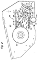
- the tensioning mechanism includes a pair of lower and upper swing arms 64, 66, both of which are attached to a pivot bearing 68, which extends from the end plate 20.
- the swivel arms 64, 66 are on a central region 70 of each swivel arm 64, 66 am Swivel bearing 68 attached.
- Each swivel arm 64, 66 has one radial arm 72 extending from the central region 70 to the outside extends and ends at an outer end 74.
- a roll 76 preferably made of plastic, is on everyone Swivel arm 64, 66 at the outer end 74 of the radial arm 72 rotatably attached.
- a torsion spring 80 is around that Pivot bearing 68 wound and has opposite ends 82, which are inserted into openings 84 in each of the pivot arms 64, 66 are. The torsion spring 80 presses against the swivel arms 64, 66, around the two rollers 76 against the runs 60, 62 of the chain 56 to press.
- the swivel arms 64, 66 additionally have a second radial one Arm 88 on.
- the radial arm 88 includes an arcuate one Slot 90 which is substantially concentric with the pivot bearing 68 and an opening 92 which is radial in the same Distance from pivot bearing 68 is like slot 90.
- a Pin in the form of a fastening device 94 with nut and Screw is through the opening 92 of a swivel arm and the Slot 90 of the other swivel arm inserted.
- the pin 94 limits the rotation of the pivot arms 64, 66 relative to each other on the extension of slot 90. That is primarily an aid during assembly to the movement of the Limit swivel arms 64, 66 before the chain 56 to the Pinion 50, 52 is placed.
- the swivel arms 64, 66 are one embodiment identical.
- the swing arms 64, 66 are individually around the pivot bearing 68 rotatable and against each other through the Torsion spring 80 coupled to provide the tension force.
- This provides a tensioning mechanism that does not Setting needed.
- the desired tension is determined by the Spring 80 provided.
- a sleeve 96 encloses the fastening device 94 Nut and bolt and is replaced by a second Fastening device 95 with nut and screw in place and Held place.
- the sleeve 96 can engage the chain 56 to ensure that the chain 56 is not the Torsion spring 80 touches.
- the sleeve 96 is shown in FIG Embodiment because of the close proximity of the pivot bearing 68 to Pinion 50 and the small diameter of the pinion 50 expedient.
- a pulley 100 is on the incoming drive shaft 46 coupled.
- a belt 104 is around the pulley 100 and around a pulley 102 on the housing of the drive gear of the Cutter bar 30 placed.
- the strap is also around a pair moving rollers 106 and 108 placed.
- the moving one Roller 108 is rotatably attached to a frame bracket 110 which is in turn fixed on the cross tube 44.
- the moving role 106 is a tension pulley and on a third pivot arm 112 attached, which is also supported on the pivot bearing 68.
- a Rod 114 is coupled to pivot arm 112 and extends by a spring 116 around the idler roller 106 preload.
- An assembly 118 with mother and Washer that is screwed onto the rod 114 used to adjust the compression of the spring 116.
Landscapes
- Engineering & Computer Science (AREA)
- General Engineering & Computer Science (AREA)
- Life Sciences & Earth Sciences (AREA)
- Environmental Sciences (AREA)
- Mechanical Engineering (AREA)
- Outside Dividers And Delivering Mechanisms For Harvesters (AREA)
- Devices For Conveying Motion By Means Of Endless Flexible Members (AREA)
- Harvesting Machines For Root Crops (AREA)
Applications Claiming Priority (2)
| Application Number | Priority Date | Filing Date | Title |
|---|---|---|---|
| US09/364,493 US6167686B1 (en) | 1999-07-30 | 1999-07-30 | Tensioner for header of a harvester |
| US364493 | 1999-07-30 |
Publications (1)
| Publication Number | Publication Date |
|---|---|
| EP1072184A1 true EP1072184A1 (fr) | 2001-01-31 |
Family
ID=23434762
Family Applications (1)
| Application Number | Title | Priority Date | Filing Date |
|---|---|---|---|
| EP00113322A Withdrawn EP1072184A1 (fr) | 1999-07-30 | 2000-06-23 | Dispositif d'actionnement pour une unité de traitement ou transport de la récolte dans un tablier d'une moissonneuse-batteuse |
Country Status (5)
| Country | Link |
|---|---|
| US (1) | US6167686B1 (fr) |
| EP (1) | EP1072184A1 (fr) |
| AU (1) | AU769851B2 (fr) |
| BR (1) | BR0003186A (fr) |
| CA (1) | CA2298816C (fr) |
Cited By (2)
| Publication number | Priority date | Publication date | Assignee | Title |
|---|---|---|---|---|
| EP1458994A4 (fr) * | 2001-12-12 | 2006-11-15 | Dayco Products Llc | Systeme adaptatif de tendeur de courroie pour commande de poulie de charge reversible |
| WO2007124241A1 (fr) * | 2006-04-20 | 2007-11-01 | Borgwarner Inc | Mécanisme à cliquet pour transmission par chaîne |
Families Citing this family (26)
| Publication number | Priority date | Publication date | Assignee | Title |
|---|---|---|---|---|
| DE19926612A1 (de) * | 1999-06-11 | 2000-12-14 | Schaeffler Waelzlager Ohg | Riementrieb einer Brennkraftmaschine |
| US7594912B2 (en) | 2004-09-30 | 2009-09-29 | Intuitive Surgical, Inc. | Offset remote center manipulator for robotic surgery |
| US6857979B2 (en) * | 2001-10-26 | 2005-02-22 | Litens Automotive Partnership | Combination belt tensioner and idler |
| US6942589B2 (en) * | 2002-02-08 | 2005-09-13 | Dayco Products, Llc | Offset starter generator drive utilizing a fixed-offset dual-arm pivoted tensioner |
| US6652401B2 (en) * | 2002-02-11 | 2003-11-25 | The Gates Corporation | Method of tuning a belt drive system |
| GB0212649D0 (en) * | 2002-05-31 | 2002-07-10 | Ford New Holland Nv | Utility machinery and associated reversible feeder mechanisms |
| ITTO20030819A1 (it) * | 2003-10-17 | 2005-04-18 | Dayco Europe Srl | Tenditore bi-braccio per una cinghia di trasmissione di un autoveicolo. |
| US20050181901A1 (en) * | 2004-02-13 | 2005-08-18 | Chang-Hyun Shin | Double action belt tensioner |
| DE102004029829A1 (de) * | 2004-06-19 | 2005-12-29 | Daimlerchrysler Ag | Riemenspanneinrichtung und Riemengetriebe mit einer solchen Riemenspanneinrichtung |
| US9261172B2 (en) * | 2004-09-30 | 2016-02-16 | Intuitive Surgical Operations, Inc. | Multi-ply strap drive trains for surgical robotic arms |
| US10646292B2 (en) | 2004-09-30 | 2020-05-12 | Intuitive Surgical Operations, Inc. | Electro-mechanical strap stack in robotic arms |
| US7479078B2 (en) * | 2004-11-17 | 2009-01-20 | Dayco Products, Llc | Belt tensioner system |
| US7632200B2 (en) * | 2005-06-06 | 2009-12-15 | Borgwarner Inc. | Common link dual arm tensioning device |
| US7678000B2 (en) * | 2006-06-16 | 2010-03-16 | Cnh America, Llc. | Tensioning arrangement for an endless linkage |
| ES2543688T3 (es) * | 2007-11-16 | 2015-08-21 | Ketten-Wulf Betriebs-Gmbh | Medio de accionamiento y accionamiento de cadenas |
| US8065865B1 (en) * | 2010-08-17 | 2011-11-29 | Deere & Company | Spring assisted translating draper belt drive rollers for an agricultural harvesting machine |
| EP2532922B1 (fr) | 2010-09-28 | 2015-02-18 | Oxbo International Corporation | Système tendeur de tensionnement d'une courroie ou d'une châine |
| EP2777815B1 (fr) * | 2013-03-15 | 2017-07-19 | Sandvik Intellectual Property AB | Appareil de tension de courroie de concasseur |
| US9635811B2 (en) * | 2014-05-08 | 2017-05-02 | CNH Industrial America LL | Adjustable gathering chain assembly for a header of an agricultural harvester |
| US9700979B2 (en) * | 2014-09-08 | 2017-07-11 | Jpw Industries Inc. | Belt tensioner for drill press |
| BE1022840B1 (nl) | 2015-03-09 | 2016-09-20 | Cnh Industrial Belgium Nv | Maaier voor een oogstmachine die een verplaatsbare maaibalktafel bevat |
| DE102018215451A1 (de) * | 2018-09-11 | 2020-03-12 | Bayerische Motoren Werke Aktiengesellschaft | Kraftrad mit einer Spannvorrichtung zum Spannen eines Zugorgans und Spannvorrichtung für ein Kraftrad |
| DE102022100471B4 (de) * | 2022-01-11 | 2025-07-17 | Bayerische Motoren Werke Aktiengesellschaft | Riementrieb zum Antreiben eines Kraftfahrzeugs, insbesondere eines Kraftrads, sowie Kraftfahrzeug, insbesondere Kraftrad |
| EP4285707A1 (fr) * | 2022-05-30 | 2023-12-06 | CNH Industrial Belgium N.V. | Alimentation de système d'entraînement de vis sans fin pour un collecteur de ramassage de gazon |
| DE102022130748A1 (de) * | 2022-11-21 | 2024-05-23 | Deere & Company | Erntevorsatz mit höhenbeweglicher Querförderschnecke |
| CN116138033B (zh) * | 2023-03-13 | 2026-03-20 | 九方泰禾国际重工(青岛)股份有限公司 | 一种茎穗兼收机及工作方法 |
Citations (6)
| Publication number | Priority date | Publication date | Assignee | Title |
|---|---|---|---|---|
| DE1936308U (de) * | 1962-09-25 | 1966-04-07 | Faun Werke | Kettenspanner fuer einen in beiden richtungen leistung uebertragenden kettentrieb. |
| DE2014807A1 (de) * | 1969-03-27 | 1970-10-08 | International Harvester Company, Chicago, 111. (V.St.A.) | Vorrichtung zur selbsttätigen Regelung der Fahrgeschwindigkeit selbstfahrender landwirtschaftlicher Erntemaschinen, insbesondere Mähdrescher |
| DE1923779A1 (de) * | 1969-05-09 | 1971-06-09 | Int Harvester Co | Vorrichtung zur automatischen Steuerung der Bodengeschwindigkeit einer mit einer Aufnahmevorrichtung,einer Plattform und einer Bearbeitungsvorrichtung versehenen Erntemaschine duch Abtastung des Drehmoments eines umlaufenden Teiles der Maschine |
| EP0680687A1 (fr) * | 1994-05-07 | 1995-11-08 | New Holland Belgium N.V. | Dispositif d'inversion pour une moissonneuse aericole |
| EP0757190A1 (fr) * | 1995-08-04 | 1997-02-05 | Castelgarden S.P.A. | Tendeur de chaîne élastique bidirectionnel |
| US5778644A (en) * | 1996-08-09 | 1998-07-14 | Deere & Company | Crop harvesting platform having a reversible drive for the reel, cutterbar center-feed augers and conditioner rolls |
Family Cites Families (24)
| Publication number | Priority date | Publication date | Assignee | Title |
|---|---|---|---|---|
| US1257660A (en) * | 1914-06-12 | 1918-02-26 | Charles A Brown | Transmission mechanism. |
| US3374686A (en) * | 1965-12-01 | 1968-03-26 | Brewer Machine & Gear Co | Drive-tensioning apparatus |
| US3628315A (en) * | 1970-08-17 | 1971-12-21 | Robert W Bartholomew | Mower safety device |
| US3673884A (en) * | 1970-11-16 | 1972-07-04 | Bombardier Ltd | Chain tensioning device for snowmobile type transmission |
| US4069719A (en) | 1976-06-18 | 1978-01-24 | Cancilla Philip S | Chain tensioner for chain drives |
| DE2739543A1 (de) * | 1977-09-02 | 1979-03-08 | Fichtel & Sachs Ag | Kettenschaltung |
| US4278211A (en) * | 1979-02-06 | 1981-07-14 | Sperry Corporation | Tensioning mechanism for forage harvester feed roll assembly |
| US4416647A (en) | 1981-05-26 | 1983-11-22 | Dayco Corporation | Belt tensioner |
| FR2508862A1 (fr) * | 1981-07-03 | 1983-01-07 | Simplex Ets | Dispositif de commande assurant des positions multiples preetablies et controlees, applicable en particulier aux changements de vitesse pour les cycles et vehicules similaires |
| US4511348A (en) | 1982-06-24 | 1985-04-16 | Sperry Corporation | Drive tensioning apparatus |
| US4658573A (en) * | 1985-04-08 | 1987-04-21 | New Holland Inc. | Signal device for bale forming machine |
| US4713042A (en) * | 1986-03-24 | 1987-12-15 | Daniel Imhoff | Automatic transmission for a bicycle |
| US4768997A (en) | 1987-03-10 | 1988-09-06 | Tecumseh Products Company | Belt drive system for dual input transmissions/transaxles |
| JP2532236B2 (ja) * | 1987-03-23 | 1996-09-11 | 富士重工業株式会社 | ねじ式オ−トテンシヨナ |
| US4758208A (en) * | 1987-07-13 | 1988-07-19 | General Motors Corporation | Automatic belt tensioner for vehicle combined starter-generator |
| JPH01143454U (fr) | 1988-03-28 | 1989-10-02 | ||
| FR2640714B1 (fr) * | 1988-12-16 | 1991-02-08 | Caoutchouc Manuf Plastique | Dispositif de tension par transmission par lien souple a double galet sur bague elastique de torsion |
| US5221236A (en) * | 1990-07-10 | 1993-06-22 | Raymer Matthew C | Belt tensioning device for belt driven bicycle |
| US5613918A (en) | 1995-04-06 | 1997-03-25 | Fleischman; Daniel G. | Bidirectional torque responsive belt tensioner |
| US5557912A (en) * | 1995-06-13 | 1996-09-24 | Western Combine Corporation | Stripper header attachment |
| IT1277549B1 (it) * | 1995-09-06 | 1997-11-11 | Idit Int Design Nv | Gruppo trasmissione particolarmente per biciclette o simili |
| US5695421A (en) * | 1996-02-21 | 1997-12-09 | Shimano Inc. | Elastomer coated coil spring and chain derailleur employing same |
| US5964674A (en) * | 1997-03-21 | 1999-10-12 | The Gates Corporation | Belt tensioner with bottom wall of base juxtaposed pivot arm |
| US5924947A (en) * | 1997-07-23 | 1999-07-20 | Ford Global Technologies, Inc. | Asymmetrically hydraulically damped drivebelt tensioner for automotive engine |
-
1999
- 1999-07-30 US US09/364,493 patent/US6167686B1/en not_active Expired - Fee Related
-
2000
- 2000-02-15 CA CA002298816A patent/CA2298816C/fr not_active Expired - Fee Related
- 2000-06-23 EP EP00113322A patent/EP1072184A1/fr not_active Withdrawn
- 2000-06-26 AU AU42670/00A patent/AU769851B2/en not_active Ceased
- 2000-07-27 BR BR0003186-0A patent/BR0003186A/pt not_active IP Right Cessation
Patent Citations (6)
| Publication number | Priority date | Publication date | Assignee | Title |
|---|---|---|---|---|
| DE1936308U (de) * | 1962-09-25 | 1966-04-07 | Faun Werke | Kettenspanner fuer einen in beiden richtungen leistung uebertragenden kettentrieb. |
| DE2014807A1 (de) * | 1969-03-27 | 1970-10-08 | International Harvester Company, Chicago, 111. (V.St.A.) | Vorrichtung zur selbsttätigen Regelung der Fahrgeschwindigkeit selbstfahrender landwirtschaftlicher Erntemaschinen, insbesondere Mähdrescher |
| DE1923779A1 (de) * | 1969-05-09 | 1971-06-09 | Int Harvester Co | Vorrichtung zur automatischen Steuerung der Bodengeschwindigkeit einer mit einer Aufnahmevorrichtung,einer Plattform und einer Bearbeitungsvorrichtung versehenen Erntemaschine duch Abtastung des Drehmoments eines umlaufenden Teiles der Maschine |
| EP0680687A1 (fr) * | 1994-05-07 | 1995-11-08 | New Holland Belgium N.V. | Dispositif d'inversion pour une moissonneuse aericole |
| EP0757190A1 (fr) * | 1995-08-04 | 1997-02-05 | Castelgarden S.P.A. | Tendeur de chaîne élastique bidirectionnel |
| US5778644A (en) * | 1996-08-09 | 1998-07-14 | Deere & Company | Crop harvesting platform having a reversible drive for the reel, cutterbar center-feed augers and conditioner rolls |
Cited By (4)
| Publication number | Priority date | Publication date | Assignee | Title |
|---|---|---|---|---|
| EP1458994A4 (fr) * | 2001-12-12 | 2006-11-15 | Dayco Products Llc | Systeme adaptatif de tendeur de courroie pour commande de poulie de charge reversible |
| WO2007124241A1 (fr) * | 2006-04-20 | 2007-11-01 | Borgwarner Inc | Mécanisme à cliquet pour transmission par chaîne |
| CN101427054B (zh) * | 2006-04-20 | 2011-06-08 | 博格华纳公司 | 用于链条驱动的棘齿张紧器 |
| US8066600B2 (en) | 2006-04-20 | 2011-11-29 | Borgwarner Inc. | Ratchet mechanism for a chain drive |
Also Published As
| Publication number | Publication date |
|---|---|
| BR0003186A (pt) | 2001-03-13 |
| US6167686B1 (en) | 2001-01-02 |
| CA2298816C (fr) | 2003-06-10 |
| CA2298816A1 (fr) | 2001-01-30 |
| AU769851B2 (en) | 2004-02-05 |
| AU4267000A (en) | 2001-02-01 |
Similar Documents
| Publication | Publication Date | Title |
|---|---|---|
| AU769851B2 (en) | Tensioner for the header of a harvester | |
| DE10029372C2 (de) | Stellanordnung für die Zinkenträger einer Haspel für ein Schneidwerk | |
| DE60206697T2 (de) | Mäh- und Konditioniereinrichtung | |
| EP1082893B1 (fr) | Faucheuse et véhicule ou appareil | |
| EP1621064B1 (fr) | Conveyeur-élévateur pour une machine agricole | |
| DE3202382C2 (de) | Reversierbare Stauförderbahn | |
| EP0651939B1 (fr) | Strippeur pour dispositif convoyeur sur une moissonneuse | |
| DE2649001A1 (de) | Antriebsstrecke und uebertragung fuer futtererntemaschinen | |
| DE60300438T2 (de) | Arbeitsmaschine und zugehörige umkehrbare Zuführungseinrichtungen | |
| DE3033229A1 (de) | Erntevorrichtung fuer vorzugsweise in reihen angepflanztes erntegut mit vier foerderbahnen und einer leitvorrichtung | |
| DE19529067C2 (de) | Vorsatzgerät für eine Halmguterntemaschine | |
| DE2014807A1 (de) | Vorrichtung zur selbsttätigen Regelung der Fahrgeschwindigkeit selbstfahrender landwirtschaftlicher Erntemaschinen, insbesondere Mähdrescher | |
| EP1245141B1 (fr) | Appareil de travail à unités de travail pivotables | |
| EP1082892A1 (fr) | Faucheuse et véhicule ou appareil | |
| DE2820268A1 (de) | Motor-rasenmaeher | |
| DE7806036U1 (de) | Rundballenpresse fuer heu und anderes faseriges erntegut mit einer baender-spannvorrichtung fuer die baender zur ballenformung | |
| DE1582276B1 (de) | Maehbinder | |
| DE2528828C2 (de) | Antriebsanordnung für einen Feldhäcksler | |
| DE2140577C2 (de) | Feldhäcksler | |
| DE3042254C2 (de) | Umschnürungsvorrichtung an landwirtschaftlichen Rollballenpressen | |
| DE3780942T2 (de) | Mittel zur neutralisierung des antriebs fuer die haspel von landwirtschaftlichen maschinen. | |
| EP0095690A1 (fr) | Presse à balles rondes dont la chambre de compactage comprend une entrée pour le matériau | |
| DE102021105149A1 (de) | Verstellbare Winkelausrichtung einer frei mitlaufenden Riemenscheibe eines Riementriebs | |
| DE19750954A1 (de) | Aufnahmeeinrichtung einer landwirtschaftlichen Erntemaschine | |
| DE4019123B4 (de) | Einzugsvorrichtung für Feldhäcksler |
Legal Events
| Date | Code | Title | Description |
|---|---|---|---|
| PUAI | Public reference made under article 153(3) epc to a published international application that has entered the european phase |
Free format text: ORIGINAL CODE: 0009012 |
|
| AK | Designated contracting states |
Kind code of ref document: A1 Designated state(s): BE DE DK FR IT |
|
| AX | Request for extension of the european patent |
Free format text: AL;LT;LV;MK;RO;SI |
|
| 17P | Request for examination filed |
Effective date: 20010731 |
|
| AKX | Designation fees paid |
Free format text: BE DE DK FR IT |
|
| 17Q | First examination report despatched |
Effective date: 20030324 |
|
| GRAP | Despatch of communication of intention to grant a patent |
Free format text: ORIGINAL CODE: EPIDOSNIGR1 |
|
| STAA | Information on the status of an ep patent application or granted ep patent |
Free format text: STATUS: THE APPLICATION IS DEEMED TO BE WITHDRAWN |
|
| 18D | Application deemed to be withdrawn |
Effective date: 20040323 |