EP1072358A2 - Glasscheibenrand Bearbeitungsvorrichtung - Google Patents
Glasscheibenrand Bearbeitungsvorrichtung Download PDFInfo
- Publication number
- EP1072358A2 EP1072358A2 EP00830478A EP00830478A EP1072358A2 EP 1072358 A2 EP1072358 A2 EP 1072358A2 EP 00830478 A EP00830478 A EP 00830478A EP 00830478 A EP00830478 A EP 00830478A EP 1072358 A2 EP1072358 A2 EP 1072358A2
- Authority
- EP
- European Patent Office
- Prior art keywords
- plate
- grinding wheel
- supporting
- supporting structure
- plane
- Prior art date
- Legal status (The legal status is an assumption and is not a legal conclusion. Google has not performed a legal analysis and makes no representation as to the accuracy of the status listed.)
- Granted
Links
Images




Classifications
-
- B—PERFORMING OPERATIONS; TRANSPORTING
- B24—GRINDING; POLISHING
- B24B—MACHINES, DEVICES, OR PROCESSES FOR GRINDING OR POLISHING; DRESSING OR CONDITIONING OF ABRADING SURFACES; FEEDING OF GRINDING, POLISHING, OR LAPPING AGENTS
- B24B49/00—Measuring or gauging equipment for controlling the feed movement of the grinding tool or work; Arrangements of indicating or measuring equipment, e.g. for indicating the start of the grinding operation
-
- B—PERFORMING OPERATIONS; TRANSPORTING
- B24—GRINDING; POLISHING
- B24B—MACHINES, DEVICES, OR PROCESSES FOR GRINDING OR POLISHING; DRESSING OR CONDITIONING OF ABRADING SURFACES; FEEDING OF GRINDING, POLISHING, OR LAPPING AGENTS
- B24B51/00—Arrangements for automatic control of a series of individual steps in grinding a workpiece
-
- B—PERFORMING OPERATIONS; TRANSPORTING
- B24—GRINDING; POLISHING
- B24B—MACHINES, DEVICES, OR PROCESSES FOR GRINDING OR POLISHING; DRESSING OR CONDITIONING OF ABRADING SURFACES; FEEDING OF GRINDING, POLISHING, OR LAPPING AGENTS
- B24B9/00—Machines or devices designed for grinding edges or bevels on work or for removing burrs; Accessories therefor
- B24B9/02—Machines or devices designed for grinding edges or bevels on work or for removing burrs; Accessories therefor characterised by a special design with respect to properties of materials specific to articles to be ground
- B24B9/06—Machines or devices designed for grinding edges or bevels on work or for removing burrs; Accessories therefor characterised by a special design with respect to properties of materials specific to articles to be ground of non-metallic inorganic material, e.g. stone, ceramics, porcelain
- B24B9/08—Machines or devices designed for grinding edges or bevels on work or for removing burrs; Accessories therefor characterised by a special design with respect to properties of materials specific to articles to be ground of non-metallic inorganic material, e.g. stone, ceramics, porcelain of glass
- B24B9/10—Machines or devices designed for grinding edges or bevels on work or for removing burrs; Accessories therefor characterised by a special design with respect to properties of materials specific to articles to be ground of non-metallic inorganic material, e.g. stone, ceramics, porcelain of glass of plate glass
- B24B9/107—Machines or devices designed for grinding edges or bevels on work or for removing burrs; Accessories therefor characterised by a special design with respect to properties of materials specific to articles to be ground of non-metallic inorganic material, e.g. stone, ceramics, porcelain of glass of plate glass for glass plates while they are turning
Definitions
- the present invention relates to the field of apparatus for machining the edges of glass plates, in particular for bevelling the said edges.
- a first category of known apparatus is that of the so-called manual bevelling apparatus.
- Such apparatus comprise means for supporting the plate in a horizontal plane and for making it rotate about a vertical axis, as well as a rotary grinding wheel carried at the end of an arm which can be oriented about a vertical axis and which is pushed manually so as to cause the grinding wheel to come into contact with the edge of the plate during rotation of the latter.
- the known apparatus of this first type consequently require the intervention of skilled staff for a non-negligible length of time.
- the horizontal position of the plate means that the cooling water used during machining and the swarf remain on the plate while the latter is being machined.
- a second type of known apparatus is represented by the so-called automatic bevelling apparatus.
- These apparatus are equipped with a copying device consisting of a pair of tracer points, which come into contact with the edge of the plate.
- the grinding wheel is consequently controlled in such a way as to follow the profile of the plate thus detected, whilst the latter is made to turn in a horizontal plane about a vertical axis.
- This second type of apparatus presents the same drawback mentioned above deriving from the horizontal position of the plate as regards the problem of cooling water and swarf remaining on the plate during machining.
- the said second type of apparatus works by copying the plate edge, it is necessary for the edge to be finished before bevelling is carried out.
- the working cycle with said apparatus first of all comprises grinding of the edge of the glass plate, next machining of the bevel, and finally a second machining of the edge that is formed on the glass plate by the bevelling operation.
- Execution of the cycle described above entails a relatively long time, with a consequent low productivity of the apparatus, due to the fact that all the plates coming out of the bevelling apparatus must undergo re-machining.
- This apparatus is a numerical control bevelling apparatus in which the plate is set in a horizontal plane. This first of all involves the usual drawback due to the persistence of water and swarf on the plate. In addition, this latter type of apparatus presents a few problems in the machining of very thin plates. During the bevelling operation, the grinding wheel is pressed vertically with its front face inclined against the peripheral edge of the glass plate, which is thus subjected to a bending stress. The plate must therefore be adequately supported and guided in the vicinity of its edge in order to prevent it from breaking. In more traditional apparatus this is obtained by providing supporting and guiding wheels underneath the plate in the vicinity of the grinding wheel.
- the main purpose of the present invention is to overcome such drawbacks.
- a further purpose of the present invention is to achieve the targets specified above, without at the same time introducing the drawbacks that are characteristic of the apparatus known from the documents EP-A-0 798 075 and FR-A-2 545 025.
- the subject of the invention is therefore an apparatus for machining the edge of glass plates, in particular for bevelling the edges of glass plates, comprising means for supporting the plate in a vertical plane, or anyway in a plane substantially inclined with respect to the horizontal, and for causing the plate to rotate in this plane, and a machining head comprising a grinding wheel designed to come into contact with the edge of the plate during rotation of the latter, characterized in that the aforesaid means for supporting the plate are carried by a slide or carriage mounted on a fixed supporting structure in such a way that it is free to move along a horizontal direction away from/up to said grinding wheel, said apparatus comprising a numerical control system for controlling movement of said grinding wheel and of said plate-supporting means.
- the aforesaid machining head is provided with means for orienting the grinding wheel about three mutually orthogonal axes which cross in an area corresponding to the grinding wheel. More precisely, the machining head comprises:
- the grinding wheel can be oriented during machining in order to guarantee perfect execution both of the process of grinding the edge of the plate and of the bevelling operation.
- the apparatus comprises a pair of wheels for supporting and guiding the glass plate in the proximity of the grinding wheel, these wheels being interchangeable in the operating position for grinding and bevelling of the plate. Thanks to the structure and arrangement described above, the apparatus according to the invention enables a series of advantages to be obtained. In the first place, since the plate is kept in a substantially vertical plane, the water and swarf do not remain on the plate during machining. In the second place, the apparatus is equipped with a numerical control system for controlling the movements of the plate and of the grinding wheel during machining. The profile of the plate to be machined may be entered in the control system, without any need for setting up the mechanical tracer-point devices for feeling the profile.
- the plate can be supported, both during grinding of the edge and during bevelling, by means of supporting wheels adjacent to the grinding wheel, which avoid the need to use jigs (with consequent advantages in terms of tooling time and apparatus output) and guarantee execution of the operation without any breakages of the glass plates even when the latter are very thin.
- jigs with consequent advantages in terms of tooling time and apparatus output
- a preliminary operation of grinding the plate edge is not required prior to carrying out the bevelling process.
- the arrangement of the means for supporting the plate on a mobile slide in a horizontal direction when bringing the grinding wheel up to or moving it away from the edge also enables solution of the problems that led to the failure of the apparatus illustrated in EP-A-0 798 075 being implemented.
- the particular geometry of the machining head described above enables the position of the grinding wheel with respect to the plate to be adapted in an optimal way during execution of the bevelling operation.
- the possibility of oscillation of the third supporting structure about the aforesaid third axis enables adjustment of the bevel angle.
- the possibility of rotation of the first supporting structure about the aforesaid first axis makes it possible to maintain the basic plane of the grinding wheel, once the latter has been inclined for carrying out bevelling, constantly tangential to the profile of the plate during machining.
- the possibility of oscillation of the second supporting structure about the aforesaid second horizontal axis makes it possible to perform the so-called "anti-sticking" function in order to reduce considerably the area of contact between the basic surface of the grinding wheel and the edge of the plate.
- the apparatus according to the invention is able to overcome all the drawbacks referred to above present in the various types of known apparatus, and in particular is able to carry out without problems both the grinding process and the process of bevelling even thin plates, with a high production efficiency.
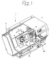
- the reference number 1 designates, as a whole, an apparatus for machining the edges of glass plates, comprising a fixed structure 2 provided with a protective casing 3 (illustrated only partially in Figure 1).
- the apparatus 1 comprises an assembly 4 for supporting the glass plate to be machined.
- the said assembly is provided, in a way in itself known, with a plurality of sucker-type devices 5 which have the purpose of holding the glass plate stably on the assembly 4.
- the said assembly basically includes a turntable 6 lying in a plane substantially inclined with respect to the horizontal plane.
- the invention does not rule out the possibility of the inclination reaching 90°, so as to set the glass plate in a perfectly vertical plane, but, as has already been pointed out, it applies in any case also to solutions which envisage the plate being set in a plane closely approaching the vertical plane or anyway strongly inclined (over 10°) with respect to the horizontal plane, as in the case of the example illustrated.
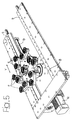
- the turntable 6 is mounted, in such a way that it can turn about an axis 7 normal to the plane in which it lies, on a slide 8 (see Figure 5) which is mounted in a sliding way along a horizontal direction Y between two guides 9 carried by the fixed structure 2 of the apparatus.
- This structure comprises reference means 10 (see Figure 2) for positioning the glass plate, the said means 10 being adjustable on respective guides 11 and moreover having an inoperative or retracted position (underneath the plate-resting surface), where they are taken after the plate has been picked up by the sucker-type devices 5 so as to render the edge of the plate to be machined completely accessible.
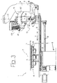
- the movement of the slide 8 is controlled by an electric motor 12 by means of an external thread 13 which engages an internal thread (not illustrated) rigidly connected to the slide 8 (see Figure 3).
- the assembly 4 for supporting the glass plate can be moved up to or away from a machining head 13 carrying a grinding wheel 14 for machining the edge of the glass plate L (see Figure 3) mounted on the assembly 4.
- the machining head 13 is supported by a fixed supporting structure or mount 15 (see Figures 2 and 3) which is rigidly connected to the fixed structure 2 of the apparatus.
- the mount 15 supports in rotation a first supporting structure 16 about an axis C set perpendicular to the plane in which the plate L lies, i.e., parallel to the axis 7 of rotation of the assembly 4 for supporting the plate.
- the angular position of the first supporting structure 16 about the axis C is controlled by an electric motor 18 ( Figure 2) mounted on the mount 15.
- the first supporting structure 16 supports a second supporting structure 19 (see Figure 3) about an axis T that is parallel to the plane in which the plate L lies.
- the angular position of the second supporting structure 19 about the axis T is controlled by a hydraulic cylinder (not illustrated in the drawings).
- the second supporting structure 19 defines an arched guide 20 on which a third supporting structure 21 is mounted in a sliding way.
- a third supporting structure 21 mounted so that it can turn on said third supporting structure 21 is the spindle of the grinding wheel 14, the axis of which is designated by 22 in Figure 3.
- the third supporting structure 21 can be made to oscillate about an axis B that is parallel to the plane in which the plate L lies and orthogonal to the axis T.
- the three axes C, T, B meet in a point corresponding to the grinding wheel 14.
- the position of the third supporting structure 21 on the arched guide 20 is controlled by a motor unit 23 which operates a pinion (not illustrated) which meshes with a toothing (not illustrated either) associated to the guide 20.
- the motor means which control movement about the axes C, T, B, as well as the motor 12 which controls displacement of the slide 8 carrying the assembly 4 for supporting the glass plate are all controlled by a numerical control system, the cabinet of which is designated by 24 in Figure 1.
- the numerical control system can send commands to the apparatus to carry out both grinding of the edge of the glass plate L (see Figures 6 and 7) and bevelling (see Figures 8 and 9).
- a respective wheel 25 or 26 is activated for supporting the edge of the plate L in the vicinity of the grinding wheel 14, so as to guarantee perfect execution of machining without any risk of the plate breaking, even in the case of a very thin plate.
- the two wheels 25, 26 are interchangeable in the operating position, according to the type of machining to be carried out.
- each of said wheels is mounted so that it is free to turn at the end of a telescopic supporting element 27, controlled, for instance, by a hydraulic cylinder, in order to enable displacement of each of said wheels 25, 26 between a raised, operating, position and a lowered, inoperative, position.
- the grinding wheel 14 is inclined as illustrated in Figure 8, by rotation about the axis B. This rotation is obtained by translating the supporting structure 21 on the arched guide 20.
- the maximum angular oscillation that may be set about the axis B is, in the case of the example illustrated, approximately 45°.
- the slide 8 is brought up to the machining head 13 so as to bring the edge of the plate L up against the grinding wheel 14.
- the assembly 4 is set in rotation about the axis 7 so as to bring the various portions of the edge of the plate L, in succession, into contact with the active surface of the grinding wheel 14 (see Figures 8 and 9).
- the first supporting structure 16 is oriented about the axis C in such a way as to maintain the basic plane of the grinding wheel 14 constantly tangential to the edge of the plate, whatever the profile of the latter may be.
- the various motor means with which the apparatus is equipped are governed by the numerical control system 24 according to a pre-set program so as to follow the profile of the plate L, which is preliminarily acquired by the control system.
- the grinding wheel 14 ( Figure 8) exerts a thrust downwards on the edge of the plate, which is, however, adequately supported by the wheel 26. In this way, the risk of breakage of the plate is prevented, even in the case of a very thin plate, without thereby any need for using jigs as, instead, is necessary in the case of some known apparatus that were mentioned at the beginning of the present description.
- the machining head also includes means for varying the position of the grinding wheel 14 along the axis 22, so as to adapt said position to the thickness of the plate.
- a grinding-wheel magazine is envisaged (only partially visible in the right-hand top part of Figure 2) for automatic replacement of the grinding wheel.
- the grinding wheel 14 is positioned with its axis 22 perpendicular to the plane in which the plate L lies, as illustrated in Figures 6 and 7. Also in this case the plate is adequately supported by the wheel 25, which is set further away from the grinding wheel 14 than the wheel 26, in order to prevent any interference with the grinding wheel 14 when the latter is in the position corresponding to the grinding operation.
- the apparatus according to the invention is able to combine the advantages of known apparatus without, however, presenting any of the drawbacks that have been mentioned at the beginning of the present description.
- the apparatus according to the invention is able to carry out both the grinding operation and the bevelling operation on plates that are even very thin, without any risk of the plates breaking and without any of the drawbacks discussed previously.
Landscapes
- Engineering & Computer Science (AREA)
- Mechanical Engineering (AREA)
- Chemical & Material Sciences (AREA)
- Ceramic Engineering (AREA)
- Inorganic Chemistry (AREA)
- Grinding And Polishing Of Tertiary Curved Surfaces And Surfaces With Complex Shapes (AREA)
- Re-Forming, After-Treatment, Cutting And Transporting Of Glass Products (AREA)
Applications Claiming Priority (2)
| Application Number | Priority Date | Filing Date | Title |
|---|---|---|---|
| IT1999TO000656A IT1308106B1 (it) | 1999-07-23 | 1999-07-23 | Macchina per la lavorazione del bordo di lastre di vetro. |
| ITTO990656 | 1999-07-23 |
Publications (3)
| Publication Number | Publication Date |
|---|---|
| EP1072358A2 true EP1072358A2 (de) | 2001-01-31 |
| EP1072358A3 EP1072358A3 (de) | 2003-11-05 |
| EP1072358B1 EP1072358B1 (de) | 2004-09-15 |
Family
ID=11417994
Family Applications (1)
| Application Number | Title | Priority Date | Filing Date |
|---|---|---|---|
| EP00830478A Expired - Lifetime EP1072358B1 (de) | 1999-07-23 | 2000-07-07 | Glasscheibenrand-Bearbeitungsvorrichtung |
Country Status (4)
| Country | Link |
|---|---|
| EP (1) | EP1072358B1 (de) |
| AT (1) | ATE276071T1 (de) |
| DE (1) | DE60013711D1 (de) |
| IT (1) | IT1308106B1 (de) |
Cited By (5)
| Publication number | Priority date | Publication date | Assignee | Title |
|---|---|---|---|---|
| CN111037405A (zh) * | 2019-12-12 | 2020-04-21 | 常州工业职业技术学院 | 一种玻璃用全自动双面打磨装置 |
| CN113414644A (zh) * | 2021-07-23 | 2021-09-21 | 武汉爱拼建筑劳务有限公司 | 一种轻质水泥墙板制作加工方法 |
| CN113752158A (zh) * | 2021-09-07 | 2021-12-07 | 河北光兴半导体技术有限公司 | 一种上磨边磨头总成及研磨机 |
| CN113770853A (zh) * | 2021-09-07 | 2021-12-10 | 河北光兴半导体技术有限公司 | 一种下磨边磨头总成及研磨机 |
| CN118322033A (zh) * | 2024-05-14 | 2024-07-12 | 成都牧马山玻璃有限公司 | 一种异形磨边机 |
Family Cites Families (3)
| Publication number | Priority date | Publication date | Assignee | Title |
|---|---|---|---|---|
| GB235953A (en) * | 1924-03-26 | 1925-06-26 | Bernard Gwynne Twyford Hawkes | Improvements relating to machinery employed in glass bevelling or grinding and/or polishing operations |
| JP2859389B2 (ja) * | 1990-07-09 | 1999-02-17 | 坂東機工 株式会社 | ガラス板の周辺エッジを研削加工する方法及びこの方法を実施するガラス板の数値制御研削機械 |
| FI86263C (fi) * | 1990-11-22 | 1992-08-10 | Tamglass Oy | Skaer- och slipanordning foer en glasskivkant. |
-
1999
- 1999-07-23 IT IT1999TO000656A patent/IT1308106B1/it active
-
2000
- 2000-07-07 AT AT00830478T patent/ATE276071T1/de not_active IP Right Cessation
- 2000-07-07 EP EP00830478A patent/EP1072358B1/de not_active Expired - Lifetime
- 2000-07-07 DE DE60013711T patent/DE60013711D1/de not_active Expired - Lifetime
Cited By (6)
| Publication number | Priority date | Publication date | Assignee | Title |
|---|---|---|---|---|
| CN111037405A (zh) * | 2019-12-12 | 2020-04-21 | 常州工业职业技术学院 | 一种玻璃用全自动双面打磨装置 |
| CN113414644A (zh) * | 2021-07-23 | 2021-09-21 | 武汉爱拼建筑劳务有限公司 | 一种轻质水泥墙板制作加工方法 |
| CN113414644B (zh) * | 2021-07-23 | 2023-04-28 | 武汉市政环境工程建设有限公司 | 一种轻质水泥墙板制作加工方法 |
| CN113752158A (zh) * | 2021-09-07 | 2021-12-07 | 河北光兴半导体技术有限公司 | 一种上磨边磨头总成及研磨机 |
| CN113770853A (zh) * | 2021-09-07 | 2021-12-10 | 河北光兴半导体技术有限公司 | 一种下磨边磨头总成及研磨机 |
| CN118322033A (zh) * | 2024-05-14 | 2024-07-12 | 成都牧马山玻璃有限公司 | 一种异形磨边机 |
Also Published As
| Publication number | Publication date |
|---|---|
| ITTO990656A1 (it) | 2001-01-23 |
| EP1072358A3 (de) | 2003-11-05 |
| ATE276071T1 (de) | 2004-10-15 |
| DE60013711D1 (de) | 2004-10-21 |
| EP1072358B1 (de) | 2004-09-15 |
| IT1308106B1 (it) | 2001-11-29 |
Similar Documents
| Publication | Publication Date | Title |
|---|---|---|
| EP1867430B1 (de) | Schleif- und Poliermaschine zum Schleifen und/oder Polieren von Werkstücken in optischer Qualität | |
| DE69711022T2 (de) | Verfahren zum schleifen von kanten | |
| CN104084651B (zh) | 线性模组的加工方法 | |
| CN101693298B (zh) | 自动车边倒角机 | |
| CA2966681C (en) | Machine for cutting stone material | |
| JP2006312234A (ja) | 高性能フライス削り・旋削装置および特に眼鏡レンズを加工する方法 | |
| US6478658B1 (en) | Apparatus for generating lens surfaces | |
| KR0151401B1 (ko) | 착색 또는 착색되지 않은 평탄 유리, 플레이트 유리 또는 평탄화된 유리의 박판 및, 이로부터 획득된 제품의 내측 각도를 베벨가공하는 방법 및 장치 | |
| CN105174705A (zh) | 玻璃加工一体机 | |
| EP1072358B1 (de) | Glasscheibenrand-Bearbeitungsvorrichtung | |
| GB2063734A (en) | Machine for grinding toothed cutting tools | |
| CN216802274U (zh) | 一种高精度铝单板焊接装置 | |
| CN201505848U (zh) | 倒角机 | |
| CN109290613A (zh) | 一种倒角机自动生产线 | |
| CN209754732U (zh) | 一种球头铣刀研磨机 | |
| CN215788384U (zh) | 用于镜架内圈加工的加工装置 | |
| US4909679A (en) | Plastic lens edge beveler | |
| JPH071231A (ja) | 面取り兼シェービング装置 | |
| CN220407483U (zh) | 一种型材加工设备 | |
| RU2116166C1 (ru) | Устройство для обработки направляющих станин | |
| JPH05212611A (ja) | 溶接角柱のデポ処理兼用開先加工装置 | |
| JPH02185363A (ja) | ガラス板加工機械 | |
| CN112453595A (zh) | 一种数控加工用内螺纹磨床及其调整方法 | |
| CN221364066U (zh) | 一种双工位零件内孔磨削机构 | |
| CN217647933U (zh) | 一种具有高效的多工位雕铣机 |
Legal Events
| Date | Code | Title | Description |
|---|---|---|---|
| PUAI | Public reference made under article 153(3) epc to a published international application that has entered the european phase |
Free format text: ORIGINAL CODE: 0009012 |
|
| AK | Designated contracting states |
Kind code of ref document: A2 Designated state(s): AT BE CH CY DE DK ES FI FR GB GR IE IT LI LU MC NL PT SE |
|
| AX | Request for extension of the european patent |
Free format text: AL;LT;LV;MK;RO;SI |
|
| RAP1 | Party data changed (applicant data changed or rights of an application transferred) |
Owner name: GIEFFE S.R.L Owner name: BIESSE S.P.A. |
|
| PUAL | Search report despatched |
Free format text: ORIGINAL CODE: 0009013 |
|
| AK | Designated contracting states |
Kind code of ref document: A3 Designated state(s): AT BE CH CY DE DK ES FI FR GB GR IE IT LI LU MC NL PT SE |
|
| AX | Request for extension of the european patent |
Extension state: AL LT LV MK RO SI |
|
| RIC1 | Information provided on ipc code assigned before grant |
Ipc: 7B 24B 51/00 B Ipc: 7B 24B 49/00 B Ipc: 7B 24B 9/10 A |
|
| 17P | Request for examination filed |
Effective date: 20031103 |
|
| GRAP | Despatch of communication of intention to grant a patent |
Free format text: ORIGINAL CODE: EPIDOSNIGR1 |
|
| GRAS | Grant fee paid |
Free format text: ORIGINAL CODE: EPIDOSNIGR3 |
|
| AKX | Designation fees paid |
Designated state(s): AT BE CH CY DE DK ES FI FR GB GR IE IT LI LU MC NL PT SE |
|
| GRAA | (expected) grant |
Free format text: ORIGINAL CODE: 0009210 |
|
| AK | Designated contracting states |
Kind code of ref document: B1 Designated state(s): AT BE CH CY DE DK ES FI FR GB GR IE IT LI LU MC NL PT SE |
|
| PG25 | Lapsed in a contracting state [announced via postgrant information from national office to epo] |
Ref country code: NL Free format text: LAPSE BECAUSE OF FAILURE TO SUBMIT A TRANSLATION OF THE DESCRIPTION OR TO PAY THE FEE WITHIN THE PRESCRIBED TIME-LIMIT Effective date: 20040915 Ref country code: LI Free format text: LAPSE BECAUSE OF FAILURE TO SUBMIT A TRANSLATION OF THE DESCRIPTION OR TO PAY THE FEE WITHIN THE PRESCRIBED TIME-LIMIT Effective date: 20040915 Ref country code: CH Free format text: LAPSE BECAUSE OF FAILURE TO SUBMIT A TRANSLATION OF THE DESCRIPTION OR TO PAY THE FEE WITHIN THE PRESCRIBED TIME-LIMIT Effective date: 20040915 Ref country code: AT Free format text: LAPSE BECAUSE OF FAILURE TO SUBMIT A TRANSLATION OF THE DESCRIPTION OR TO PAY THE FEE WITHIN THE PRESCRIBED TIME-LIMIT Effective date: 20040915 Ref country code: BE Free format text: LAPSE BECAUSE OF FAILURE TO SUBMIT A TRANSLATION OF THE DESCRIPTION OR TO PAY THE FEE WITHIN THE PRESCRIBED TIME-LIMIT Effective date: 20040915 Ref country code: FI Free format text: LAPSE BECAUSE OF FAILURE TO SUBMIT A TRANSLATION OF THE DESCRIPTION OR TO PAY THE FEE WITHIN THE PRESCRIBED TIME-LIMIT Effective date: 20040915 Ref country code: FR Free format text: LAPSE BECAUSE OF FAILURE TO SUBMIT A TRANSLATION OF THE DESCRIPTION OR TO PAY THE FEE WITHIN THE PRESCRIBED TIME-LIMIT Effective date: 20040915 |
|
| REG | Reference to a national code |
Ref country code: GB Ref legal event code: FG4D Ref country code: CH Ref legal event code: EP |
|
| REG | Reference to a national code |
Ref country code: IE Ref legal event code: FG4D |
|
| REF | Corresponds to: |
Ref document number: 60013711 Country of ref document: DE Date of ref document: 20041021 Kind code of ref document: P |
|
| PG25 | Lapsed in a contracting state [announced via postgrant information from national office to epo] |
Ref country code: DK Free format text: LAPSE BECAUSE OF FAILURE TO SUBMIT A TRANSLATION OF THE DESCRIPTION OR TO PAY THE FEE WITHIN THE PRESCRIBED TIME-LIMIT Effective date: 20041215 Ref country code: SE Free format text: LAPSE BECAUSE OF FAILURE TO SUBMIT A TRANSLATION OF THE DESCRIPTION OR TO PAY THE FEE WITHIN THE PRESCRIBED TIME-LIMIT Effective date: 20041215 Ref country code: GR Free format text: LAPSE BECAUSE OF FAILURE TO SUBMIT A TRANSLATION OF THE DESCRIPTION OR TO PAY THE FEE WITHIN THE PRESCRIBED TIME-LIMIT Effective date: 20041215 |
|
| PG25 | Lapsed in a contracting state [announced via postgrant information from national office to epo] |
Ref country code: DE Free format text: LAPSE BECAUSE OF FAILURE TO SUBMIT A TRANSLATION OF THE DESCRIPTION OR TO PAY THE FEE WITHIN THE PRESCRIBED TIME-LIMIT Effective date: 20041216 |
|
| PG25 | Lapsed in a contracting state [announced via postgrant information from national office to epo] |
Ref country code: ES Free format text: LAPSE BECAUSE OF FAILURE TO SUBMIT A TRANSLATION OF THE DESCRIPTION OR TO PAY THE FEE WITHIN THE PRESCRIBED TIME-LIMIT Effective date: 20041226 |
|
| REG | Reference to a national code |
Ref country code: CH Ref legal event code: PL |
|
| NLV1 | Nl: lapsed or annulled due to failure to fulfill the requirements of art. 29p and 29m of the patents act | ||
| PG25 | Lapsed in a contracting state [announced via postgrant information from national office to epo] |
Ref country code: GB Free format text: LAPSE BECAUSE OF NON-PAYMENT OF DUE FEES Effective date: 20050707 Ref country code: CY Free format text: LAPSE BECAUSE OF FAILURE TO SUBMIT A TRANSLATION OF THE DESCRIPTION OR TO PAY THE FEE WITHIN THE PRESCRIBED TIME-LIMIT Effective date: 20050707 Ref country code: IE Free format text: LAPSE BECAUSE OF NON-PAYMENT OF DUE FEES Effective date: 20050707 Ref country code: LU Free format text: LAPSE BECAUSE OF NON-PAYMENT OF DUE FEES Effective date: 20050707 |
|
| PLBE | No opposition filed within time limit |
Free format text: ORIGINAL CODE: 0009261 |
|
| STAA | Information on the status of an ep patent application or granted ep patent |
Free format text: STATUS: NO OPPOSITION FILED WITHIN TIME LIMIT |
|
| PG25 | Lapsed in a contracting state [announced via postgrant information from national office to epo] |
Ref country code: MC Free format text: LAPSE BECAUSE OF NON-PAYMENT OF DUE FEES Effective date: 20050731 |
|
| 26N | No opposition filed |
Effective date: 20050616 |
|
| EN | Fr: translation not filed | ||
| GBPC | Gb: european patent ceased through non-payment of renewal fee |
Effective date: 20050707 |
|
| REG | Reference to a national code |
Ref country code: IE Ref legal event code: MM4A |
|
| PG25 | Lapsed in a contracting state [announced via postgrant information from national office to epo] |
Ref country code: PT Free format text: LAPSE BECAUSE OF NON-PAYMENT OF DUE FEES Effective date: 20050215 |
|
| PGFP | Annual fee paid to national office [announced via postgrant information from national office to epo] |
Ref country code: IT Payment date: 20090703 Year of fee payment: 10 |
|
| PG25 | Lapsed in a contracting state [announced via postgrant information from national office to epo] |
Ref country code: IT Free format text: LAPSE BECAUSE OF NON-PAYMENT OF DUE FEES Effective date: 20100707 |