EP1072761A2 - Perfektioniertes Ventilbetätigungsgerät und ein mit diesem Gerät ausgerüsteter Verbrennungsmotor - Google Patents
Perfektioniertes Ventilbetätigungsgerät und ein mit diesem Gerät ausgerüsteter Verbrennungsmotor Download PDFInfo
- Publication number
- EP1072761A2 EP1072761A2 EP00402104A EP00402104A EP1072761A2 EP 1072761 A2 EP1072761 A2 EP 1072761A2 EP 00402104 A EP00402104 A EP 00402104A EP 00402104 A EP00402104 A EP 00402104A EP 1072761 A2 EP1072761 A2 EP 1072761A2
- Authority
- EP
- European Patent Office
- Prior art keywords
- axis
- valve
- cam
- rotation
- adjustment
- Prior art date
- Legal status (The legal status is an assumption and is not a legal conclusion. Google has not performed a legal analysis and makes no representation as to the accuracy of the status listed.)
- Granted
Links
Images

Classifications
-
- F—MECHANICAL ENGINEERING; LIGHTING; HEATING; WEAPONS; BLASTING
- F01—MACHINES OR ENGINES IN GENERAL; ENGINE PLANTS IN GENERAL; STEAM ENGINES
- F01L—CYCLICALLY OPERATING VALVES FOR MACHINES OR ENGINES
- F01L13/00—Modifications of valve-gear to facilitate reversing, braking, starting, changing compression ratio, or other specific operations
- F01L13/0015—Modifications of valve-gear to facilitate reversing, braking, starting, changing compression ratio, or other specific operations for optimising engine performances by modifying valve lift according to various working parameters, e.g. rotational speed, load, torque
- F01L13/0021—Modifications of valve-gear to facilitate reversing, braking, starting, changing compression ratio, or other specific operations for optimising engine performances by modifying valve lift according to various working parameters, e.g. rotational speed, load, torque by modification of rocker arm ratio
-
- F—MECHANICAL ENGINEERING; LIGHTING; HEATING; WEAPONS; BLASTING
- F01—MACHINES OR ENGINES IN GENERAL; ENGINE PLANTS IN GENERAL; STEAM ENGINES
- F01L—CYCLICALLY OPERATING VALVES FOR MACHINES OR ENGINES
- F01L13/00—Modifications of valve-gear to facilitate reversing, braking, starting, changing compression ratio, or other specific operations
- F01L13/0015—Modifications of valve-gear to facilitate reversing, braking, starting, changing compression ratio, or other specific operations for optimising engine performances by modifying valve lift according to various working parameters, e.g. rotational speed, load, torque
- F01L13/0063—Modifications of valve-gear to facilitate reversing, braking, starting, changing compression ratio, or other specific operations for optimising engine performances by modifying valve lift according to various working parameters, e.g. rotational speed, load, torque by modification of cam contact point by displacing an intermediate lever or wedge-shaped intermediate element, e.g. Tourtelot
-
- F—MECHANICAL ENGINEERING; LIGHTING; HEATING; WEAPONS; BLASTING
- F01—MACHINES OR ENGINES IN GENERAL; ENGINE PLANTS IN GENERAL; STEAM ENGINES
- F01L—CYCLICALLY OPERATING VALVES FOR MACHINES OR ENGINES
- F01L2305/00—Valve arrangements comprising rollers
Definitions
- the present invention relates to a device for controlling a valve and an internal combustion engine fitted with this device.
- One of the main criteria for the design and development of an internal combustion engine most often consists in increasing the engine performance for high speed without degrading the performance, and in particular the available torque, at low and medium revs.
- variable distribution systems it is known to use three-dimensional cams, that is to say the profile is variable along their axis of rotation.
- Such a design allows, thanks to a displacement of the camshaft parallel to its axis of rotation, to obtain different distribution configurations.
- This design is particularly complex and leads to an increase in size longitudinal of the engine.
- FR-A-2,453,979 describes a device for controlling a valve of an internal combustion engine, of the type comprising a rocker arm, mounted articulated on a support, around a first fixed oscillation axis, provided with a first arm requesting the free end of the valve stem and a second arm biased by a rotary control cam, and means for valve lift adjustment.
- the means of adjusting the valve lift described in this document including an eccentric associated with an axis of rotation of the rocker arm, are relatively complex.
- the object of the invention is to propose a control device a simple and inexpensive valve, of reduced longitudinal dimensions, this by avoiding as much as possible the use of elements sensitive to wear, in particular of elements continually or frequently requested in rotation.
- the invention relates to a control device a valve, of the aforementioned type, characterized in that the adjusting means of the valve lift include an adjusting member, mounted hinged on the second arm of the rocker arm around a movable oscillation axis, a first contact roller with the control cam, which is mounted articulated on the adjustment member around a first movable axis of rotation, and a second contact roller with an adjustment cam, which is mounted articulated on the adjustment member around a second mobile axis of rotation, the axes of oscillation and rotation being all distinct and substantially parallel to each other, the adjustment cam being mounted articulated on the support around a second fixed oscillation axis substantially parallel to the first fixed swing axis so that for a constant position of the cam control corresponding to a position of the valve where it is open, the movements of this adjustment cam cause the distance to vary between the first fixed oscillation axis and the second mobile axis of rotation.
- the invention also relates to a combustion engine internal characterized in that it comprises a device for controlling valve as defined above, the valve preferably being a intake valve.
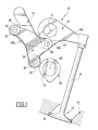
- Figures 1 and 2 are similar elevational views showing a valve control device according to two embodiments of the invention respectively.
- FIG. 1 shows a device 10 according to a first embodiment of the invention for controlling a valve 12 of internal combustion engine.
- This control device 10 is arranged in a cylinder head 14 of the engine.
- the valve 12 is movable between a closed position, such as shown in Figure 1, supported on a seat 16 formed in the cylinder head 14, and an open position (not shown).
- the valve 12 is resiliently returned to its closed position using conventional means not shown.
- control device 10 is intended to actuate an engine intake valve. However, alternatively, this same device 10 could be used to actuate a valve exhaust.
- the control device 10 comprises a rocker arm 18, mounted articulated on the cylinder head 14, around a fixed oscillation axis F1.
- the rocker 18 is provided with a first arm 18A urging the free end of the tail 20 of the valve 12 and of a second arm 18B biased by a cam rotary control 22. It will be noted that the rocker arm 18 forms a lever of the first kind.
- the cam 22 is carried by a conventional camshaft 24 mounted rotatable around a fixed axis of rotation F2 forming the axis of rotation of the cam 22.
- the control device 10 also includes means for regulating the lift of the valve 12 comprising an adjusting member 28 generally triangular in shape.
- the adjusting member 28 is mounted articulated on the second arm 18B of the rocker arm around a mobile oscillation axis M1.
- the regulator 28 carries two rotary rollers 30, 32.
- a first roller 30 is in contact with the control cam 22.
- This first roller 30 is mounted articulated on the member adjustment 28 around a first movable axis of rotation R1.
- the second pebble 32 is in contact with an adjustment cam 34.
- This second roller 32 is mounted articulated on the adjusting member 28 around a second axis of rotation mobile R2.
- the axes F1, F2, M1, R1 and R2 are substantially parallel to each other. It will also be noted that the three mobile axes M1, R1 and R2 form, in a plane perpendicular to them, the three vertices of a triangle. All the axes F1, F2, M1, R1 and R2 are distinct two by two.
- the adjustment cam 34 is hinged on the cylinder head 14 around another fixed axis of oscillation F3 substantially parallel to the previous one fixed oscillation axis F1 so that for a constant position of the cam control 22 corresponding to a position of the valve where the latter is open, the movements of this adjustment cam 34 cause the distance between the fixed oscillation axis F1 and the second mobile axis of rotation R2.
- the contact surface of the adjustment cam 34 with the second roller 32 is delimited by a curvilinear surface 36 which is curved substantially around the second movable axis of rotation R2.
- the fixed oscillation axis F3 coincides with the first axis of mobile oscillation M1 when the valve 12 is in a position of reference, namely the closed position as illustrated in FIG. 1.
- the adjustment cam 34 is moved using means conventional comprising, for example, an electric or hydraulic actuator.
- the rotary cam 22 urges the adjusting member 28 by through the first roller 30.
- This adjusting member 28 articulated on the rocker arm 18 and rolling support on the ramp 36 via the second roller 32, urges the rocker arm 18 so as to actuate the valve 12.
- the second roller 32 rolls on the ramp 36.
- the cam is controlled adjustment 34 so as to rotate it around the fixed axis F3, which has effect, for a constant position of the corresponding control cam 22 at a position of the valve 12 where the latter is open, to modify the distance between the fixed oscillation axis F1 and the second mobile axis of rotation R2. Changing this distance changes the lift valve maximum 12.
- the curved ramp 36 continues with a part 36A of reverse curvature and of which at least the part adjacent to the ramp 36 is circular and centered on the axis F3.
- the arrangement is such that the roller 32 is is in contact with this circular part when the valve is closed.
- the setting of the valve lift can be continuously produced due to the fact that the adjustment cam 34 can move continuously around the fixed axis F3.
- the engine comprises an associated crankshaft to the valve controller.
- the curve of the valve lift depending on the angle of rotation of the crankshaft conventionally has a shape general bell (see for example FR-A-2,453,979).
- FIG. 2 a second embodiment is shown. of the control device 10 according to the invention.
- the elements similar to those of FIG. 1 are designated by references identical.
- the control device 10 comprises means for adjusting the timing angle of the control cam 22.
- timing adjustment means comprise a pivot 40, materializing the first mobile axis of rotation R1, mounted movable in a curvilinear light 42 curving around the fixed axis of rotation F2 of the cam 22.
- the curvilinear light 42 is centered on an axis of setting C coinciding with the fixed axis of rotation F2 of the control cam 22 when the valve 12 is in a reference position, namely its closed position as illustrated in figure 2.
- the pivot 40 is moved in the curvilinear lumen 42 using conventional means comprising, for example, an electric actuator or hydraulic. These means also make it possible to immobilize the pivot 40 in the light 42 in the desired timing adjustment position.
- the adjusting means of the timing illustrated in FIG. 2 make it possible to vary the delay or advancing the opening and closing of the valve 12.
- the device for controlling a valve according to the invention allows the valve lift to be adjusted continuously, using a adjustment cam 34 whose movements are limited, which reduces the risk of wear.
- the opening and closing of the valve are carried out in a progressive and silent manner, this using means reduced dimensions, especially in the longitudinal direction of the engine, namely the direction parallel to the fixed axis F1 of oscillation of the rocker arm.
- the different valve lift curves in function of the angle of rotation of the crankshaft obtained for different adjustments of the position of the adjustment cam 34 are symmetrical, the delay at the intake opening (in the case of an intake valve) can be canceled by the means for adjusting the angular setting of the cam ordered.
- the device of the invention can be used in an engine comprising one or two camshafts.
Landscapes
- Engineering & Computer Science (AREA)
- Mechanical Engineering (AREA)
- General Engineering & Computer Science (AREA)
- Valve Device For Special Equipments (AREA)
- Valve-Gear Or Valve Arrangements (AREA)
Applications Claiming Priority (2)
| Application Number | Priority Date | Filing Date | Title |
|---|---|---|---|
| FR9909811A FR2796983B1 (fr) | 1999-07-28 | 1999-07-28 | Dispositif perfectionne de commande d'une soupape et moteur a combustion interne muni de ce dispostif |
| FR9909811 | 1999-07-28 |
Publications (3)
| Publication Number | Publication Date |
|---|---|
| EP1072761A2 true EP1072761A2 (de) | 2001-01-31 |
| EP1072761A3 EP1072761A3 (de) | 2002-01-16 |
| EP1072761B1 EP1072761B1 (de) | 2005-03-16 |
Family
ID=9548631
Family Applications (1)
| Application Number | Title | Priority Date | Filing Date |
|---|---|---|---|
| EP00402104A Expired - Lifetime EP1072761B1 (de) | 1999-07-28 | 2000-07-21 | Perfektioniertes Ventilbetätigungsgerät und ein mit diesem Gerät ausgerüsteter Verbrennungsmotor |
Country Status (4)
| Country | Link |
|---|---|
| EP (1) | EP1072761B1 (de) |
| AT (1) | ATE291151T1 (de) |
| DE (1) | DE60018650T2 (de) |
| FR (1) | FR2796983B1 (de) |
Cited By (6)
| Publication number | Priority date | Publication date | Assignee | Title |
|---|---|---|---|---|
| EP1205643A1 (de) * | 2000-11-13 | 2002-05-15 | Stefan Battlogg | Ventieltrieb für eine Verbrennungskraftmaschine |
| EP1357266A1 (de) * | 2002-04-26 | 2003-10-29 | LECAL, Roger | Ventilsteuerungseinrichtung mit variablem Ventilhub, variabler Nockenwellenwinkelstellung, variabler Ventilanzahl und Brennkraftmaschine mit demselben |
| WO2005090758A1 (ja) * | 2004-03-23 | 2005-09-29 | Mitsubishi Fuso Truck And Bus Corporation | 内燃機関の可変動弁装置 |
| FR2882781A1 (fr) * | 2005-03-07 | 2006-09-08 | Peugeot Citroen Automobiles Sa | Dispositif commandant l'ouverture et la fermeture d'une ou de plusieurs soupapes d'un moteur a combustion interne ainsi que moteur a combustion interne comprenant un tel dispositif |
| CN100406689C (zh) * | 2004-04-27 | 2008-07-30 | 三菱扶桑卡客车公司 | 内燃机的可变气门机构 |
| CN100410498C (zh) * | 2004-03-19 | 2008-08-13 | 三菱扶桑卡客车株式会社 | 内燃机的可变气门传动装置 |
Family Cites Families (4)
| Publication number | Priority date | Publication date | Assignee | Title |
|---|---|---|---|---|
| GB190906650A (en) * | 1909-03-19 | 1909-10-14 | Paxman & Co Ltd Davey | Improvements in Valve Gear for Internal Combustion Engines. |
| DE3438556A1 (de) * | 1984-10-20 | 1986-04-24 | Mtu Motoren- Und Turbinen-Union Friedrichshafen Gmbh, 7990 Friedrichshafen | Ventilsteuerung einer aufgeladenen viertakt-brennkraftmaschine |
| DE3833540A1 (de) * | 1988-10-01 | 1990-04-12 | Peter Prof Dr Ing Kuhn | Vorrichtung zur betaetigung der ventile an verbrennungsmotoren mit veraenderlicher ventilerhebungskurve |
| DE4220816A1 (de) * | 1992-06-25 | 1994-01-05 | Schaeffler Waelzlager Kg | Variable Ventilsteuerung mittels Änderung der Hebelverhältnisse bei Kipp- oder Schlepphebeln von Ventiltrieben |
-
1999
- 1999-07-28 FR FR9909811A patent/FR2796983B1/fr not_active Expired - Fee Related
-
2000
- 2000-07-21 AT AT00402104T patent/ATE291151T1/de not_active IP Right Cessation
- 2000-07-21 DE DE60018650T patent/DE60018650T2/de not_active Expired - Lifetime
- 2000-07-21 EP EP00402104A patent/EP1072761B1/de not_active Expired - Lifetime
Cited By (8)
| Publication number | Priority date | Publication date | Assignee | Title |
|---|---|---|---|---|
| EP1205643A1 (de) * | 2000-11-13 | 2002-05-15 | Stefan Battlogg | Ventieltrieb für eine Verbrennungskraftmaschine |
| EP1357266A1 (de) * | 2002-04-26 | 2003-10-29 | LECAL, Roger | Ventilsteuerungseinrichtung mit variablem Ventilhub, variabler Nockenwellenwinkelstellung, variabler Ventilanzahl und Brennkraftmaschine mit demselben |
| FR2839112A1 (fr) * | 2002-04-26 | 2003-10-31 | Roger Lecal | Mecanisme de distribution a levee angle d'ouverture calage et nombre de soupapes variables et moteur a combustion interne disposant de ce mecanisme |
| CN100410498C (zh) * | 2004-03-19 | 2008-08-13 | 三菱扶桑卡客车株式会社 | 内燃机的可变气门传动装置 |
| WO2005090758A1 (ja) * | 2004-03-23 | 2005-09-29 | Mitsubishi Fuso Truck And Bus Corporation | 内燃機関の可変動弁装置 |
| US7159550B2 (en) | 2004-03-23 | 2007-01-09 | Mitsubishi Fuso Truck And Bus Corporation | Variable valve train of internal combustion engine |
| CN100406689C (zh) * | 2004-04-27 | 2008-07-30 | 三菱扶桑卡客车公司 | 内燃机的可变气门机构 |
| FR2882781A1 (fr) * | 2005-03-07 | 2006-09-08 | Peugeot Citroen Automobiles Sa | Dispositif commandant l'ouverture et la fermeture d'une ou de plusieurs soupapes d'un moteur a combustion interne ainsi que moteur a combustion interne comprenant un tel dispositif |
Also Published As
| Publication number | Publication date |
|---|---|
| EP1072761B1 (de) | 2005-03-16 |
| FR2796983B1 (fr) | 2001-10-26 |
| EP1072761A3 (de) | 2002-01-16 |
| DE60018650D1 (de) | 2005-04-21 |
| DE60018650T2 (de) | 2006-05-04 |
| ATE291151T1 (de) | 2005-04-15 |
| FR2796983A1 (fr) | 2001-02-02 |
Similar Documents
| Publication | Publication Date | Title |
|---|---|---|
| EP0460988B1 (de) | Steuervorrichtung mit Nockenwelle und Kraftübertragungsmittel mit Rolle | |
| EP0097665B1 (de) | Verstellbare ventilsteuerung einer viertakt-brennkraftmaschine | |
| FR2461108A1 (fr) | Mecanisme de commande de soupape pour moteurs a combustion interne | |
| EP1072762B1 (de) | Ventilbetätigungsgerät und ein mit diesem Gerät ausgerüsteter Verbrennungsmotor | |
| FR2665483A1 (fr) | Appareil de reglage de la commande des soupapes d'un moteur a combustion interne. | |
| FR2663682A1 (fr) | Dispositif a amplitude variable pour la levee d'au moins une soupape de moteur a combustion interne. | |
| EP1072761B1 (de) | Perfektioniertes Ventilbetätigungsgerät und ein mit diesem Gerät ausgerüsteter Verbrennungsmotor | |
| FR2688828A1 (fr) | Mecanisme reglable de commande de soupapes dans un moteur a combustion interne. | |
| FR2522723A1 (fr) | Dispositif de distribution pour moteur axial | |
| FR2546967A1 (fr) | Mecanisme de commande de soupapes pour moteur a combustion interne a pistons | |
| EP0882549A1 (de) | Bandschleifmaschine für zylindrische Lagerflächen von Wellen | |
| EP0216647B1 (de) | Ventilantriebsvorrichtung für eine Brennkraftmaschine mit abschaltbaren Kipphebeln | |
| FR2724975A1 (fr) | Dispositif pour l'actionnement d'au moins une soupape de moteur a combustion interne | |
| FR2570123A1 (fr) | Dispositif de commande variable d'une soupape a tige pour moteur a combustion interne | |
| FR2733455A1 (fr) | Dispositif pour regler des lames de pliage d'un cylindre porte-lames de pliage | |
| FR2663078A1 (fr) | Dispositif a linguet et a amplitude variable pour la levee d'une soupape de moteur a combustion interne. | |
| FR2583105A1 (fr) | Dispositif de commande variable d'une soupape a tige de moteur a combustion interne | |
| EP0495326B1 (de) | Riemenspannungseinstellvorrichtung für den Antrieb eines Kraftfahrzeugmotor-Zusatzaggregates | |
| EP0185570B1 (de) | Einzelswinghebel zur Betätigung von zwei Ventilen | |
| EP0623737A1 (de) | Variable Ventilsteuereinrichtung für eine Brennkraftmaschine | |
| EP1197640B1 (de) | Ventilsteuerungseinrichtung mit mehreren Konfigurationen | |
| FR2787136A1 (fr) | Dispositif de variation de la distribution d'un moteur thermique a soupapes commandees | |
| EP0945599A1 (de) | Absperrklappe für eine Leitung und Brennkraftmaschine mit einer solchen Vorrichtung | |
| JP2636741B2 (ja) | バルブタイミング調整装置 | |
| FR3125852A1 (fr) | Ensemble de frein de parking a deplacement d’un doigt de blocage simplifie |
Legal Events
| Date | Code | Title | Description |
|---|---|---|---|
| PUAI | Public reference made under article 153(3) epc to a published international application that has entered the european phase |
Free format text: ORIGINAL CODE: 0009012 |
|
| AK | Designated contracting states |
Kind code of ref document: A2 Designated state(s): AT BE CH CY DE DK ES FI FR GB GR IE IT LI LU MC NL PT SE |
|
| AX | Request for extension of the european patent |
Free format text: AL;LT;LV;MK;RO;SI |
|
| PUAL | Search report despatched |
Free format text: ORIGINAL CODE: 0009013 |
|
| AK | Designated contracting states |
Kind code of ref document: A3 Designated state(s): AT BE CH CY DE DK ES FI FR GB GR IE IT LI LU MC NL PT SE |
|
| AX | Request for extension of the european patent |
Free format text: AL;LT;LV;MK;RO;SI |
|
| 17P | Request for examination filed |
Effective date: 20020620 |
|
| AKX | Designation fees paid |
Free format text: AT BE CH CY DE DK ES FI FR GB GR IE IT LI LU MC NL PT SE |
|
| 17Q | First examination report despatched |
Effective date: 20040325 |
|
| GRAP | Despatch of communication of intention to grant a patent |
Free format text: ORIGINAL CODE: EPIDOSNIGR1 |
|
| GRAA | (expected) grant |
Free format text: ORIGINAL CODE: 0009210 |
|
| GRAS | Grant fee paid |
Free format text: ORIGINAL CODE: EPIDOSNIGR3 |
|
| AK | Designated contracting states |
Kind code of ref document: B1 Designated state(s): AT BE CH CY DE DK ES FI FR GB GR IE IT LI LU MC NL PT SE |
|
| PG25 | Lapsed in a contracting state [announced via postgrant information from national office to epo] |
Ref country code: FI Free format text: LAPSE BECAUSE OF FAILURE TO SUBMIT A TRANSLATION OF THE DESCRIPTION OR TO PAY THE FEE WITHIN THE PRESCRIBED TIME-LIMIT Effective date: 20050316 Ref country code: IE Free format text: LAPSE BECAUSE OF FAILURE TO SUBMIT A TRANSLATION OF THE DESCRIPTION OR TO PAY THE FEE WITHIN THE PRESCRIBED TIME-LIMIT Effective date: 20050316 Ref country code: AT Free format text: LAPSE BECAUSE OF FAILURE TO SUBMIT A TRANSLATION OF THE DESCRIPTION OR TO PAY THE FEE WITHIN THE PRESCRIBED TIME-LIMIT Effective date: 20050316 Ref country code: NL Free format text: LAPSE BECAUSE OF FAILURE TO SUBMIT A TRANSLATION OF THE DESCRIPTION OR TO PAY THE FEE WITHIN THE PRESCRIBED TIME-LIMIT Effective date: 20050316 |
|
| REG | Reference to a national code |
Ref country code: GB Ref legal event code: FG4D Free format text: NOT ENGLISH |
|
| REG | Reference to a national code |
Ref country code: CH Ref legal event code: EP |
|
| REG | Reference to a national code |
Ref country code: IE Ref legal event code: FG4D Free format text: FRENCH |
|
| REF | Corresponds to: |
Ref document number: 60018650 Country of ref document: DE Date of ref document: 20050421 Kind code of ref document: P |
|
| GBT | Gb: translation of ep patent filed (gb section 77(6)(a)/1977) |
Effective date: 20050404 |
|
| PG25 | Lapsed in a contracting state [announced via postgrant information from national office to epo] |
Ref country code: DK Free format text: LAPSE BECAUSE OF FAILURE TO SUBMIT A TRANSLATION OF THE DESCRIPTION OR TO PAY THE FEE WITHIN THE PRESCRIBED TIME-LIMIT Effective date: 20050616 Ref country code: GR Free format text: LAPSE BECAUSE OF FAILURE TO SUBMIT A TRANSLATION OF THE DESCRIPTION OR TO PAY THE FEE WITHIN THE PRESCRIBED TIME-LIMIT Effective date: 20050616 |
|
| PG25 | Lapsed in a contracting state [announced via postgrant information from national office to epo] |
Ref country code: ES Free format text: LAPSE BECAUSE OF FAILURE TO SUBMIT A TRANSLATION OF THE DESCRIPTION OR TO PAY THE FEE WITHIN THE PRESCRIBED TIME-LIMIT Effective date: 20050627 |
|
| PG25 | Lapsed in a contracting state [announced via postgrant information from national office to epo] |
Ref country code: CY Free format text: LAPSE BECAUSE OF FAILURE TO SUBMIT A TRANSLATION OF THE DESCRIPTION OR TO PAY THE FEE WITHIN THE PRESCRIBED TIME-LIMIT Effective date: 20050721 Ref country code: LU Free format text: LAPSE BECAUSE OF NON-PAYMENT OF DUE FEES Effective date: 20050721 |
|
| PG25 | Lapsed in a contracting state [announced via postgrant information from national office to epo] |
Ref country code: BE Free format text: LAPSE BECAUSE OF NON-PAYMENT OF DUE FEES Effective date: 20050731 Ref country code: CH Free format text: LAPSE BECAUSE OF NON-PAYMENT OF DUE FEES Effective date: 20050731 Ref country code: MC Free format text: LAPSE BECAUSE OF NON-PAYMENT OF DUE FEES Effective date: 20050731 Ref country code: LI Free format text: LAPSE BECAUSE OF NON-PAYMENT OF DUE FEES Effective date: 20050731 |
|
| NLV1 | Nl: lapsed or annulled due to failure to fulfill the requirements of art. 29p and 29m of the patents act | ||
| PG25 | Lapsed in a contracting state [announced via postgrant information from national office to epo] |
Ref country code: PT Free format text: LAPSE BECAUSE OF FAILURE TO SUBMIT A TRANSLATION OF THE DESCRIPTION OR TO PAY THE FEE WITHIN THE PRESCRIBED TIME-LIMIT Effective date: 20050907 |
|
| REG | Reference to a national code |
Ref country code: IE Ref legal event code: FD4D |
|
| PLBE | No opposition filed within time limit |
Free format text: ORIGINAL CODE: 0009261 |
|
| STAA | Information on the status of an ep patent application or granted ep patent |
Free format text: STATUS: NO OPPOSITION FILED WITHIN TIME LIMIT |
|
| 26N | No opposition filed |
Effective date: 20051219 |
|
| REG | Reference to a national code |
Ref country code: CH Ref legal event code: PL |
|
| REG | Reference to a national code |
Ref country code: GB Ref legal event code: 746 Effective date: 20070119 |
|
| BERE | Be: lapsed |
Owner name: PEUGEOT CITROEN AUTOMOBILES SA Effective date: 20050731 |
|
| PG25 | Lapsed in a contracting state [announced via postgrant information from national office to epo] |
Ref country code: SE Free format text: LAPSE BECAUSE OF FAILURE TO SUBMIT A TRANSLATION OF THE DESCRIPTION OR TO PAY THE FEE WITHIN THE PRESCRIBED TIME-LIMIT Effective date: 20050616 |
|
| PGFP | Annual fee paid to national office [announced via postgrant information from national office to epo] |
Ref country code: IT Payment date: 20080717 Year of fee payment: 9 |
|
| PGFP | Annual fee paid to national office [announced via postgrant information from national office to epo] |
Ref country code: GB Payment date: 20080630 Year of fee payment: 9 |
|
| GBPC | Gb: european patent ceased through non-payment of renewal fee |
Effective date: 20090721 |
|
| PG25 | Lapsed in a contracting state [announced via postgrant information from national office to epo] |
Ref country code: GB Free format text: LAPSE BECAUSE OF NON-PAYMENT OF DUE FEES Effective date: 20090721 |
|
| PG25 | Lapsed in a contracting state [announced via postgrant information from national office to epo] |
Ref country code: IT Free format text: LAPSE BECAUSE OF NON-PAYMENT OF DUE FEES Effective date: 20090721 |
|
| PGFP | Annual fee paid to national office [announced via postgrant information from national office to epo] |
Ref country code: FR Payment date: 20120806 Year of fee payment: 13 Ref country code: DE Payment date: 20120625 Year of fee payment: 13 |
|
| REG | Reference to a national code |
Ref country code: FR Ref legal event code: ST Effective date: 20140331 |
|
| PG25 | Lapsed in a contracting state [announced via postgrant information from national office to epo] |
Ref country code: DE Free format text: LAPSE BECAUSE OF NON-PAYMENT OF DUE FEES Effective date: 20140201 |
|
| REG | Reference to a national code |
Ref country code: DE Ref legal event code: R119 Ref document number: 60018650 Country of ref document: DE Effective date: 20140201 |
|
| PG25 | Lapsed in a contracting state [announced via postgrant information from national office to epo] |
Ref country code: FR Free format text: LAPSE BECAUSE OF NON-PAYMENT OF DUE FEES Effective date: 20130731 |