EP1072772A1 - Module de génération d'électricité à pile combustible et procédé de régulation de pression de la pile à combustible - Google Patents
Module de génération d'électricité à pile combustible et procédé de régulation de pression de la pile à combustible Download PDFInfo
- Publication number
- EP1072772A1 EP1072772A1 EP00402158A EP00402158A EP1072772A1 EP 1072772 A1 EP1072772 A1 EP 1072772A1 EP 00402158 A EP00402158 A EP 00402158A EP 00402158 A EP00402158 A EP 00402158A EP 1072772 A1 EP1072772 A1 EP 1072772A1
- Authority
- EP
- European Patent Office
- Prior art keywords
- pressure
- fuel cell
- turbine
- compressor
- gas
- Prior art date
- Legal status (The legal status is an assumption and is not a legal conclusion. Google has not performed a legal analysis and makes no representation as to the accuracy of the status listed.)
- Granted
Links
- 239000000446 fuel Substances 0.000 title claims abstract description 64
- 238000000034 method Methods 0.000 title claims description 5
- 239000007789 gas Substances 0.000 claims abstract description 55
- 230000001590 oxidative effect Effects 0.000 claims abstract description 32
- 239000007800 oxidant agent Substances 0.000 claims abstract description 23
- 230000005611 electricity Effects 0.000 claims abstract description 17
- 230000001105 regulatory effect Effects 0.000 claims abstract description 13
- 238000006073 displacement reaction Methods 0.000 description 2
- 238000006243 chemical reaction Methods 0.000 description 1
- 230000001276 controlling effect Effects 0.000 description 1
- 238000003487 electrochemical reaction Methods 0.000 description 1
- 239000002737 fuel gas Substances 0.000 description 1
- 230000010354 integration Effects 0.000 description 1
- 238000011144 upstream manufacturing Methods 0.000 description 1
Images
Classifications
-
- F—MECHANICAL ENGINEERING; LIGHTING; HEATING; WEAPONS; BLASTING
- F02—COMBUSTION ENGINES; HOT-GAS OR COMBUSTION-PRODUCT ENGINE PLANTS
- F02C—GAS-TURBINE PLANTS; AIR INTAKES FOR JET-PROPULSION PLANTS; CONTROLLING FUEL SUPPLY IN AIR-BREATHING JET-PROPULSION PLANTS
- F02C6/00—Plural gas-turbine plants; Combinations of gas-turbine plants with other apparatus; Adaptations of gas-turbine plants for special use
- F02C6/04—Gas-turbine plants providing heated or pressurised working fluid for other apparatus, e.g. without mechanical power output
- F02C6/10—Gas-turbine plants providing heated or pressurised working fluid for other apparatus, e.g. without mechanical power output supplying working fluid to a user, e.g. a chemical process, which returns working fluid to a turbine of the plant
- F02C6/12—Turbochargers, i.e. plants for augmenting mechanical power output of internal-combustion piston engines by increase of charge pressure
-
- F—MECHANICAL ENGINEERING; LIGHTING; HEATING; WEAPONS; BLASTING
- F02—COMBUSTION ENGINES; HOT-GAS OR COMBUSTION-PRODUCT ENGINE PLANTS
- F02C—GAS-TURBINE PLANTS; AIR INTAKES FOR JET-PROPULSION PLANTS; CONTROLLING FUEL SUPPLY IN AIR-BREATHING JET-PROPULSION PLANTS
- F02C1/00—Gas-turbine plants characterised by the use of hot gases or unheated pressurised gases, as the working fluid
- F02C1/04—Gas-turbine plants characterised by the use of hot gases or unheated pressurised gases, as the working fluid the working fluid being heated indirectly
- F02C1/05—Gas-turbine plants characterised by the use of hot gases or unheated pressurised gases, as the working fluid the working fluid being heated indirectly characterised by the type or source of heat, e.g. using nuclear or solar energy
-
- F—MECHANICAL ENGINEERING; LIGHTING; HEATING; WEAPONS; BLASTING
- F02—COMBUSTION ENGINES; HOT-GAS OR COMBUSTION-PRODUCT ENGINE PLANTS
- F02C—GAS-TURBINE PLANTS; AIR INTAKES FOR JET-PROPULSION PLANTS; CONTROLLING FUEL SUPPLY IN AIR-BREATHING JET-PROPULSION PLANTS
- F02C3/00—Gas-turbine plants characterised by the use of combustion products as the working fluid
- F02C3/04—Gas-turbine plants characterised by the use of combustion products as the working fluid having a turbine driving a compressor
- F02C3/107—Gas-turbine plants characterised by the use of combustion products as the working fluid having a turbine driving a compressor with two or more rotors connected by power transmission
- F02C3/113—Gas-turbine plants characterised by the use of combustion products as the working fluid having a turbine driving a compressor with two or more rotors connected by power transmission with variable power transmission between rotors
-
- H—ELECTRICITY
- H01—ELECTRIC ELEMENTS
- H01M—PROCESSES OR MEANS, e.g. BATTERIES, FOR THE DIRECT CONVERSION OF CHEMICAL ENERGY INTO ELECTRICAL ENERGY
- H01M8/00—Fuel cells; Manufacture thereof
- H01M8/04—Auxiliary arrangements, e.g. for control of pressure or for circulation of fluids
- H01M8/04082—Arrangements for control of reactant parameters, e.g. pressure or concentration
- H01M8/04089—Arrangements for control of reactant parameters, e.g. pressure or concentration of gaseous reactants
- H01M8/04111—Arrangements for control of reactant parameters, e.g. pressure or concentration of gaseous reactants using a compressor turbine assembly
-
- H—ELECTRICITY
- H01—ELECTRIC ELEMENTS
- H01M—PROCESSES OR MEANS, e.g. BATTERIES, FOR THE DIRECT CONVERSION OF CHEMICAL ENERGY INTO ELECTRICAL ENERGY
- H01M8/00—Fuel cells; Manufacture thereof
- H01M8/04—Auxiliary arrangements, e.g. for control of pressure or for circulation of fluids
- H01M8/04298—Processes for controlling fuel cells or fuel cell systems
- H01M8/04313—Processes for controlling fuel cells or fuel cell systems characterised by the detection or assessment of variables; characterised by the detection or assessment of failure or abnormal function
- H01M8/0438—Pressure; Ambient pressure; Flow
- H01M8/04395—Pressure; Ambient pressure; Flow of cathode reactants at the inlet or inside the fuel cell
-
- H—ELECTRICITY
- H01—ELECTRIC ELEMENTS
- H01M—PROCESSES OR MEANS, e.g. BATTERIES, FOR THE DIRECT CONVERSION OF CHEMICAL ENERGY INTO ELECTRICAL ENERGY
- H01M8/00—Fuel cells; Manufacture thereof
- H01M8/04—Auxiliary arrangements, e.g. for control of pressure or for circulation of fluids
- H01M8/04298—Processes for controlling fuel cells or fuel cell systems
- H01M8/04694—Processes for controlling fuel cells or fuel cell systems characterised by variables to be controlled
- H01M8/04746—Pressure; Flow
- H01M8/04753—Pressure; Flow of fuel cell reactants
-
- F—MECHANICAL ENGINEERING; LIGHTING; HEATING; WEAPONS; BLASTING
- F04—POSITIVE - DISPLACEMENT MACHINES FOR LIQUIDS; PUMPS FOR LIQUIDS OR ELASTIC FLUIDS
- F04C—ROTARY-PISTON, OR OSCILLATING-PISTON, POSITIVE-DISPLACEMENT MACHINES FOR LIQUIDS; ROTARY-PISTON, OR OSCILLATING-PISTON, POSITIVE-DISPLACEMENT PUMPS
- F04C18/00—Rotary-piston pumps specially adapted for elastic fluids
- F04C18/08—Rotary-piston pumps specially adapted for elastic fluids of intermeshing-engagement type, i.e. with engagement of co-operating members similar to that of toothed gearing
- F04C18/12—Rotary-piston pumps specially adapted for elastic fluids of intermeshing-engagement type, i.e. with engagement of co-operating members similar to that of toothed gearing of other than internal-axis type
- F04C18/14—Rotary-piston pumps specially adapted for elastic fluids of intermeshing-engagement type, i.e. with engagement of co-operating members similar to that of toothed gearing of other than internal-axis type with toothed rotary pistons
- F04C18/16—Rotary-piston pumps specially adapted for elastic fluids of intermeshing-engagement type, i.e. with engagement of co-operating members similar to that of toothed gearing of other than internal-axis type with toothed rotary pistons with helical teeth, e.g. chevron-shaped, screw type
-
- Y—GENERAL TAGGING OF NEW TECHNOLOGICAL DEVELOPMENTS; GENERAL TAGGING OF CROSS-SECTIONAL TECHNOLOGIES SPANNING OVER SEVERAL SECTIONS OF THE IPC; TECHNICAL SUBJECTS COVERED BY FORMER USPC CROSS-REFERENCE ART COLLECTIONS [XRACs] AND DIGESTS
- Y02—TECHNOLOGIES OR APPLICATIONS FOR MITIGATION OR ADAPTATION AGAINST CLIMATE CHANGE
- Y02E—REDUCTION OF GREENHOUSE GAS [GHG] EMISSIONS, RELATED TO ENERGY GENERATION, TRANSMISSION OR DISTRIBUTION
- Y02E60/00—Enabling technologies; Technologies with a potential or indirect contribution to GHG emissions mitigation
- Y02E60/30—Hydrogen technology
- Y02E60/50—Fuel cells
Definitions
- the present invention relates to a generation module of electricity comprising a fuel cell and a method of regulation of the pressure of the oxidant gas in a fuel cell.
- the present invention relates to a electricity generation module comprising a fuel cell supplied with oxidizer and exhaust gas.
- a fuel cell supplied with oxidizer and exhaust gas.
- the oxidizer generally used is the compressed air obtained using a compressor.
- an oxidizing circuit comprising a compressor for supplying air to the fuel cell compressed and a turbine coupled to the compressor to recover energy exhaust gas coming out of the fuel cell and transmitting it mechanically to the compressor.
- a turbo-compressor comprises a turbine driven by the flow of gases escaping from a charging device. This first turbine drives a compressor, to supply the compressed air charging device.
- US patent 4,838,020 further comprises an auxiliary burner, the pressure of the exhaust gases arriving in the turbine is regulated by closed loop by action on a burner control system.
- the invention aims to provide a solution to this problem by simplifying the pressure regulation system for the oxidant gas in a fuel cell.
- the object of the invention is also to regulate the pressure in the fuel cell whatever the operating regime of this cell fuel.
- the invention proposes for this purpose a generation module of electricity, including a fuel cell, a compressor supplying compressed fuel gas to the fuel cell, a turbine powered by fuel cell exhaust and connected mechanically to the compressor and a device for regulating the pressure of the oxidant gas in the fuel cell.
- the electricity generation module includes a dimming device of the speed of rotation of the turbine interposed in the mechanical connection between the compressor and the turbine and controlled by the regulation device the pressure of the oxidizing gas.
- the pressure of the oxidant gas in the fuel cell this varies as a function of the electric current passing through said cell at combustible.
- This operating point is not necessarily the optimum operating point corresponding to the best efficiency of the fuel cell for a given value of electric current.
- the regulation of the pressure of the oxidant gas in the fuel cell according to the invention makes it possible to optimize the variation curve over a whole operating range of the fuel cell by passing it through optimum operating points.
- the invention provides for regulating it by acting on the speed of rotation of the turbine N turbine .
- the turbine being mechanically linked to the compressor for ease of integration, action is taken on the speed of rotation of the turbine N turbine by means of a speed variator device.
- the speed variator device rotation of the turbine makes it possible to modify the drive ratio mechanical between the compressor and the turbine.
- the oxidant gas pressure regulator can include a comparator to determine a pressure difference between a required pressure and the pressure of the oxidant gas in the stack to combustible.
- the energy recovered by the turbine is transmitted mechanically to the compressor through the dimming device speed.
- the speed controller mechanically connected to the compressor and turbine, allows to link the rotation speed of the compressor at turbine speed using ratio which is the division of the speed of rotation of the turbine by the speed of rotation of the compressor.
- the device for regulating the gas pressure oxidizer includes a corrector which receives the pressure difference and generates a control signal to the speed controller of the turbine.
- This corrector can be a proportional-integral-derivative type corrector (PID) controlling the drive ratio according to the pressure deviation of the oxidant gases in the fuel cell in relation to the requested pressure value.
- PID proportional-integral-derivative type corrector
- the turbine is of the volumetric type and the electricity generation module includes a motor coupled to the compressor and the turbine.
- the invention also relates to a method for regulating the pressure of the oxidant gas from a fuel cell receiving a flow of oxidizing gas and rejecting exhaust gases.
- the gas pressure in the fuel cell is regulated by a law of control connecting this pressure of the oxidant gas in the cell to fuel to a current flowing through this fuel cell.
- the exhaust gases are injected into a turbine and we act on the speed of rotation of the turbine as a function of a pressure difference between the gas pressure oxidizer in the fuel cell and a set value of pressure.
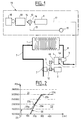
- Figure 1 shows an electricity generator module comprising a fuel cell 1, a screw compressor 2 supplying the fuel cell 1 using a compressed air flow 7.
- An engine 5 drives the screw compressor 2 by means of a drive shaft 12.
- the exhaust gas 8 from the fuel cell 1 feeds a turbine volumetric 3.
- a speed variator device 4 comprising two drive shafts 4a and 4b is mechanically connected to the turbine volumetric 3 to the screw compressor 2 and to the motor 5.
- the volumetric turbine 3 transmits the expansion energy of the gases exhaust coming from the fuel cell 1 to the variator device of speed 4 as mechanical energy through the input shaft 4a.
- This speed controller 4 transmits this mechanical energy to the screw compressor 2 as mechanical power through the drive shaft exit 4b.
- a belt 6 surrounding a part of the output shaft 4b and a part of the drive shaft 12 embodies the connection between the device variable speed drive 4 and the screw compressor 2. This link can also be carried out using a gear train.
- the compressor screw 2 receives a force torque from the speed controller 4 in addition to that provided by the motor 5.
- the mechanical link represented by the dimming device speed 4 as well as shafts 4a, 4b and 12 therefore makes it possible to recover the expansion energy of the exhaust gases 8 leaving the cell at fuel 1 and transmit it as a force couple to the screw compressor 2.
- the speed variator device 4 comprises means which are not shown to vary the drive ratio k between the turbine 3 speed and compressor speed 2.
- This drive ratio k which is the result of the division of the speed of rotation of the turbine 3 by the speed of rotation of the compressor with screw 2, is controlled by a pressure regulating device 19 comprising a regulator module 13 comprising a control law for the pressure as a function of the electric current flowing through the cell at fuel 1.
- the regulator module 13 receives a current setpoint 18 electric to be supplied by the fuel cell 1 and generates a pressure setpoint 14 which is delivered to an input of a comparator 10.
- the second input of this comparator 10 receives a signal 15 representing the exhaust gas pressure 8 measured at the outlet of the stack at fuel 1 using a pressure sensor 11.
- Comparator 10 generates a pressure difference 16 resulting from the difference between the setpoint pressure 14 and the pressure signal 15, that is to say a difference between a pressure requested and the actual pressure at the outlet of the fuel cell 1.
- the pressure difference 16 is delivered to the input of a corrector 9 by proportional-integral-derivative (PID) example which emits on its output a control signal 17 for the speed variator device 4.
- PID proportional-integral-derivative
- the pressure regulation device 19 thus makes it possible to compare a pressure setpoint 14 to a measured pressure signal 15 in fuel cell 1, then to control the dimming device speed 4.
- FIG. 2 shows a limit variation curve 20 of the pressure P of the oxidizing gas in the fuel cell 1 as a function of the electric current I passing through this fuel cell 1, in which the pressure is expressed in Pascal (Pa) and the current electric in Ampere (A).
- Pa Pascal
- Ampere Ampere
- the curve 20 has a first linear part 20a for which the electric current varies from 150 A to 250 A and the values pressure from 10 5 Pa to 2.5 * 10 5 Pa, and a second part in curvature 20b between 250 A and 350 A tending asymptotically towards a pressure value equal to 3 * 10 5 Pa.
- the variation curve 20 limit passes through points corresponding to lower limit pressure values below which the battery does not operate.
- the operating zone corresponds to a part 21 above the limit variation curve 20 in which the pressure values are greater than the lower limit pressure values.
- the forbidden zone corresponds to a part 22 below the limit variation curve 20.
- a control law 23 is deduced, shown in dotted lines in FIG. 2 and composed of three parts 23a, 23b and 23c.
- the first part 23a is a plateau with a constant pressure value equal to 1.5 * 10 5 Pa for electric current values less than or equal to 150 A.
- the second part 23b is an oblique straight line for which the pressure varies linearly as a function of the electric current between two coordinate points (150 A; 1.5 * 10 5 Pa) and (285 A; 3 * 10 5 Pa).
- the third part 23c is again a level with a constant pressure value equal to 3 * 10 5 Pa for electric current values greater than 285 A.
- the control law 23 is used by the regulation module 13.
- the electricity generator module according to the intent is energetically optimized due to the presence of a turbine at the outlet of the fuel cell which makes it possible to recover the energy contained in the exhaust gas and the fact that the gas pressure in the stack is fuel is controlled whatever the evolution of the load during operation, that is to say whatever the electric current passing through the fuel cell, thanks to the regulation of the drive ratio k.
- the device for regulating the pressure of the oxidant gas in the fuel cell is able to make change this pressure to a pressure value corresponding to a optimum operating point of the fuel cell.
Landscapes
- Engineering & Computer Science (AREA)
- Chemical & Material Sciences (AREA)
- Chemical Kinetics & Catalysis (AREA)
- Sustainable Development (AREA)
- Sustainable Energy (AREA)
- Life Sciences & Earth Sciences (AREA)
- General Chemical & Material Sciences (AREA)
- Manufacturing & Machinery (AREA)
- Electrochemistry (AREA)
- Combustion & Propulsion (AREA)
- Mechanical Engineering (AREA)
- General Engineering & Computer Science (AREA)
- Physics & Mathematics (AREA)
- High Energy & Nuclear Physics (AREA)
- Fuel Cell (AREA)
Abstract
Description
- la figure 1 est une vue schématique d'un module de génération d'électricité selon l'invention,
- la figure 2 est une courbe de variation limite de la pression du gaz comburant dans la pile à combustible en fonction du courant électrique traversant cette pile à combustible.
Claims (8)
- Module de génération d'électricité comprenant une pile à combustible (1), un compresseur (2) alimentant la pile à combustible (1) en gaz comburant comprimé (7), une turbine (3) alimentée par des gaz (8) s'échappant de la pile à combustible (1) et reliée mécaniquement au compresseur (2), et un dispositif de régulation (19) de la pression du gaz comburant dans la pile à combustible (1), caractérisé par le fait qu'il comprend un dispositif variateur (4) de la vitesse de rotation de la turbine (3) interposé dans la liaison mécanique entre le compresseur (2) et la turbine (3) et commandé par le dispositif de régulation (19) de la pression du gaz comburant.
- Module de génération d'électricité selon la revendication 1, caractérisé par le fait que le dispositif variateur (4) de la vitesse de rotation de la turbine (3) permet de modifier le rapport d'entraínement mécanique entre le compresseur (2) et la turbine (3).
- Module de génération d'électricité selon l'une des revendications précédentes, caractérisé par le fait que le dispositif de régulation (19) de la pression du gaz comburant comprend un comparateur (10) pour déterminer un écart de pression (16) entre une pression demandée (14) et la pression (15) du gaz comburant dans la pile à combustible (1).
- Module de génération d'électricité selon l'une quelconque des revendications précédentes, caractérisé par le fait que le dispositif de régulation (19) de la pression du gaz comburant comprend un correcteur (9) qui reçoit l'écart de pression (16) et génère un signal de commande (17) vers le dispositif variateur (4) de la vitesse de rotation de la turbine (2).
- Module de génération d'électricité selon l'une quelconque des revendications précédentes, caractérisé par le fait que la turbine (3) est du type volumétrique.
- Module de génération d'électricité selon l'une quelconque des revendications précédentes, caractérisé par le fait qu'il comprend un moteur (5) couplé au compresseur (2) et à la turbine (3).
- Procédé de régulation de la pression du gaz comburant d'une pile à combustible (1) recevant un flux de gaz comburant (7) et rejetant des gaz d'échappement (8), caractérisé par le fait que la pression du gaz dans la pile à combustible (1) est régulée par une loi de commande reliant la pression du gaz comburant dans la pile à combustible (1) à un courant traversant la pile à combustible (1).
- Procédé de régulation de la pression selon la revendication 7, caractérisé par le fait que les gaz d'échappement (8) sont injectés dans une turbine (3) et par le fait qu'on agit sur la vitesse de rotation de la turbine (3) en fonction d'un écart de pression (16) entre la pression du gaz comburant dans la pile à combustible (1) et une valeur de consigne de pression (14).
Applications Claiming Priority (2)
| Application Number | Priority Date | Filing Date | Title |
|---|---|---|---|
| FR9909783 | 1999-07-28 | ||
| FR9909783A FR2796981B1 (fr) | 1999-07-28 | 1999-07-28 | Module de generation d'electricite a pile a combustible et procede de regulation de pression de la pile a combustible |
Publications (2)
| Publication Number | Publication Date |
|---|---|
| EP1072772A1 true EP1072772A1 (fr) | 2001-01-31 |
| EP1072772B1 EP1072772B1 (fr) | 2005-05-11 |
Family
ID=9548615
Family Applications (1)
| Application Number | Title | Priority Date | Filing Date |
|---|---|---|---|
| EP00402158A Expired - Lifetime EP1072772B1 (fr) | 1999-07-28 | 2000-07-27 | Module de génération d'électricité à pile combustible comportant une régulation de pression de la pile à combustible |
Country Status (4)
| Country | Link |
|---|---|
| EP (1) | EP1072772B1 (fr) |
| DE (1) | DE60020022T2 (fr) |
| ES (1) | ES2238256T3 (fr) |
| FR (1) | FR2796981B1 (fr) |
Cited By (3)
| Publication number | Priority date | Publication date | Assignee | Title |
|---|---|---|---|---|
| FR2866754A1 (fr) * | 2004-02-25 | 2005-08-26 | Renault Sas | Procede de regulation de la pression d'un gaz d'echappement d'une pile a combustible de maniere a reguler l'aptitude a la condensation de ce gaz |
| US7087331B2 (en) * | 2000-10-30 | 2006-08-08 | Questair Technologies Inc. | Energy efficient gas separation for fuel cells |
| JP2018098125A (ja) * | 2016-12-16 | 2018-06-21 | トヨタ自動車株式会社 | 燃料電池システム |
Families Citing this family (1)
| Publication number | Priority date | Publication date | Assignee | Title |
|---|---|---|---|---|
| DE102012002238A1 (de) | 2012-02-04 | 2013-08-08 | Daimler Ag | Verfahren zur Druckregelung in einem Brennstoffzellensystem |
Citations (3)
| Publication number | Priority date | Publication date | Assignee | Title |
|---|---|---|---|---|
| US5645950A (en) * | 1993-06-07 | 1997-07-08 | Daimler-Benz Ag | Process for supplying air to a fuel cell system |
| EP0878859A1 (fr) * | 1997-05-15 | 1998-11-18 | Toyota Jidosha Kabushiki Kaisha | Système de piles à combustible pourvu de moyens d'enrichissement en oxygène de l'oxydant gazeux |
| WO1999013521A1 (fr) * | 1997-09-10 | 1999-03-18 | Alliedsignal Inc. | Systeme hybride d'alimentation electrique |
Family Cites Families (1)
| Publication number | Priority date | Publication date | Assignee | Title |
|---|---|---|---|---|
| US4838020A (en) | 1985-10-24 | 1989-06-13 | Mitsubishi Denki Kabushiki Kaisha | Turbocompressor system and method for controlling the same |
-
1999
- 1999-07-28 FR FR9909783A patent/FR2796981B1/fr not_active Expired - Fee Related
-
2000
- 2000-07-27 EP EP00402158A patent/EP1072772B1/fr not_active Expired - Lifetime
- 2000-07-27 ES ES00402158T patent/ES2238256T3/es not_active Expired - Lifetime
- 2000-07-27 DE DE60020022T patent/DE60020022T2/de not_active Expired - Lifetime
Patent Citations (3)
| Publication number | Priority date | Publication date | Assignee | Title |
|---|---|---|---|---|
| US5645950A (en) * | 1993-06-07 | 1997-07-08 | Daimler-Benz Ag | Process for supplying air to a fuel cell system |
| EP0878859A1 (fr) * | 1997-05-15 | 1998-11-18 | Toyota Jidosha Kabushiki Kaisha | Système de piles à combustible pourvu de moyens d'enrichissement en oxygène de l'oxydant gazeux |
| WO1999013521A1 (fr) * | 1997-09-10 | 1999-03-18 | Alliedsignal Inc. | Systeme hybride d'alimentation electrique |
Cited By (4)
| Publication number | Priority date | Publication date | Assignee | Title |
|---|---|---|---|---|
| US7087331B2 (en) * | 2000-10-30 | 2006-08-08 | Questair Technologies Inc. | Energy efficient gas separation for fuel cells |
| FR2866754A1 (fr) * | 2004-02-25 | 2005-08-26 | Renault Sas | Procede de regulation de la pression d'un gaz d'echappement d'une pile a combustible de maniere a reguler l'aptitude a la condensation de ce gaz |
| WO2005086269A1 (fr) * | 2004-02-25 | 2005-09-15 | Renault S.A.S. | Procede de regulation de la pression d'un gaz d'echappement d'une pile a combustible de maniere a reguler l'aptitude a la condensation de ce gaz |
| JP2018098125A (ja) * | 2016-12-16 | 2018-06-21 | トヨタ自動車株式会社 | 燃料電池システム |
Also Published As
| Publication number | Publication date |
|---|---|
| FR2796981B1 (fr) | 2001-09-07 |
| FR2796981A1 (fr) | 2001-02-02 |
| DE60020022D1 (de) | 2005-06-16 |
| DE60020022T2 (de) | 2006-04-27 |
| EP1072772B1 (fr) | 2005-05-11 |
| ES2238256T3 (es) | 2005-09-01 |
Similar Documents
| Publication | Publication Date | Title |
|---|---|---|
| EP0091852B1 (fr) | Procédé de régulation du rapport de mélange des propergols pour un moteur à propergols liquides | |
| FR2771450A1 (fr) | Commande de la pression d'alimentation d'un moteur a combustion interne suralimente et utilisation de cette commande | |
| FR2919673A1 (fr) | Assistance et secours a l'entrainement electrique d'une pompe a carburant dans un turbomoteur | |
| LU84259A1 (fr) | Procede pour utiliser l'energie eolienne en vue d'une production autonome d'electricite | |
| FR2541726A1 (fr) | Methode de commande du regime de ralenti d'un moteur a combustion interne prevue pour ameliorer la caracteristique de consommation de carburant du moteur | |
| FR2744173A1 (fr) | Procede permettant de commander un dispositif de recyclage des gaz d'echappement dans un moteur a combustion interne | |
| FR2835283A1 (fr) | Procede et dispositif de regulation de la pression de suralimentation d'un turbocompresseur de gaz d'echappement | |
| EP3225536A1 (fr) | Système de distribution d'énergie électrique, procédé d'alimentation d'une charge correspondant, système et procédé de propulsion pour navire | |
| FR2468742A1 (fr) | Systeme de commande pour une turbine a gaz | |
| FR2852446A1 (fr) | Moteur a combustion interne avec une pile a combustible dans un systeme d'echappement | |
| EP1072772B1 (fr) | Module de génération d'électricité à pile combustible comportant une régulation de pression de la pile à combustible | |
| WO2022208021A1 (fr) | Procédé de démarrage piloté d'une turbine a gaz d'un aéronef et systeme correspondant | |
| FR3099207A1 (fr) | Système d’alimentation en carburant d’une turbomachine | |
| EP4381182B1 (fr) | Système de conditionnement de carburant pour alimenter une turbomachine d'aéronef et procédé d'alimentation en carburant d'une turbomachine d'aéronef | |
| WO2011154528A1 (fr) | Procédé et dispositif de démarrage ou d'arrêt d'un moteur à turbine à gaz | |
| CA2093703A1 (fr) | Systeme pour le pilotage d'une torche a plasma | |
| FR3099208A1 (fr) | Circuit de carburant pour une turbomachine d’aeronef | |
| EP3574200B1 (fr) | Circuit d'alimentation en carburant de turbomachine | |
| FR2868473A1 (fr) | Procede et dispositif de gestion d'un moteur a combustion interne | |
| FR2837841A1 (fr) | Generateur de combustible gazeux | |
| FR3015672A1 (fr) | Systeme et procede de test d'une machine tournante | |
| EP2306085B1 (fr) | Brûleur à air soufflé et combustible liquide avec modulation du ratio comburant / carburant | |
| EP1097412B1 (fr) | Dispositif formant regulateur electronique de debit de fluide | |
| FR3062420A1 (fr) | Dispositif d'entrainement d'une pompe a carburant pour turbomachine | |
| EP1234697A1 (fr) | Procédé et dispositif de chauffage d'un habitacle d'un véhicule équipé d'une pile à combustible |
Legal Events
| Date | Code | Title | Description |
|---|---|---|---|
| PUAI | Public reference made under article 153(3) epc to a published international application that has entered the european phase |
Free format text: ORIGINAL CODE: 0009012 |
|
| AK | Designated contracting states |
Kind code of ref document: A1 Designated state(s): DE ES GB IT |
|
| AX | Request for extension of the european patent |
Free format text: AL;LT;LV;MK;RO;SI |
|
| 17P | Request for examination filed |
Effective date: 20010521 |
|
| AKX | Designation fees paid |
Free format text: DE ES GB IT |
|
| RAP1 | Party data changed (applicant data changed or rights of an application transferred) |
Owner name: RENAULT S.A.S. |
|
| 17Q | First examination report despatched |
Effective date: 20040226 |
|
| GRAP | Despatch of communication of intention to grant a patent |
Free format text: ORIGINAL CODE: EPIDOSNIGR1 |
|
| RTI1 | Title (correction) |
Free format text: FUEL CELL POWER GENERATING MODULE COMPRISING MEANS FOR CONTROLLING THE FUEL CELL PRESSURE |
|
| GRAS | Grant fee paid |
Free format text: ORIGINAL CODE: EPIDOSNIGR3 |
|
| GRAA | (expected) grant |
Free format text: ORIGINAL CODE: 0009210 |
|
| AK | Designated contracting states |
Kind code of ref document: B1 Designated state(s): DE ES GB IT |
|
| REG | Reference to a national code |
Ref country code: GB Ref legal event code: FG4D Free format text: NOT ENGLISH |
|
| REF | Corresponds to: |
Ref document number: 60020022 Country of ref document: DE Date of ref document: 20050616 Kind code of ref document: P |
|
| GBT | Gb: translation of ep patent filed (gb section 77(6)(a)/1977) |
Effective date: 20050603 |
|
| REG | Reference to a national code |
Ref country code: ES Ref legal event code: FG2A Ref document number: 2238256 Country of ref document: ES Kind code of ref document: T3 |
|
| PLBE | No opposition filed within time limit |
Free format text: ORIGINAL CODE: 0009261 |
|
| STAA | Information on the status of an ep patent application or granted ep patent |
Free format text: STATUS: NO OPPOSITION FILED WITHIN TIME LIMIT |
|
| 26N | No opposition filed |
Effective date: 20060214 |
|
| PGFP | Annual fee paid to national office [announced via postgrant information from national office to epo] |
Ref country code: DE Payment date: 20110722 Year of fee payment: 12 Ref country code: GB Payment date: 20110721 Year of fee payment: 12 Ref country code: ES Payment date: 20110726 Year of fee payment: 12 |
|
| PGFP | Annual fee paid to national office [announced via postgrant information from national office to epo] |
Ref country code: IT Payment date: 20110722 Year of fee payment: 12 |
|
| GBPC | Gb: european patent ceased through non-payment of renewal fee |
Effective date: 20120727 |
|
| PG25 | Lapsed in a contracting state [announced via postgrant information from national office to epo] |
Ref country code: GB Free format text: LAPSE BECAUSE OF NON-PAYMENT OF DUE FEES Effective date: 20120727 Ref country code: DE Free format text: LAPSE BECAUSE OF NON-PAYMENT OF DUE FEES Effective date: 20130201 |
|
| REG | Reference to a national code |
Ref country code: DE Ref legal event code: R119 Ref document number: 60020022 Country of ref document: DE Effective date: 20130201 |
|
| PG25 | Lapsed in a contracting state [announced via postgrant information from national office to epo] |
Ref country code: IT Free format text: LAPSE BECAUSE OF NON-PAYMENT OF DUE FEES Effective date: 20120727 |
|
| REG | Reference to a national code |
Ref country code: ES Ref legal event code: FD2A Effective date: 20131021 |
|
| PG25 | Lapsed in a contracting state [announced via postgrant information from national office to epo] |
Ref country code: ES Free format text: LAPSE BECAUSE OF NON-PAYMENT OF DUE FEES Effective date: 20120728 |