EP1072814A1 - Système de freinage d'un rotor par rapport à un stator - Google Patents
Système de freinage d'un rotor par rapport à un stator Download PDFInfo
- Publication number
- EP1072814A1 EP1072814A1 EP00401986A EP00401986A EP1072814A1 EP 1072814 A1 EP1072814 A1 EP 1072814A1 EP 00401986 A EP00401986 A EP 00401986A EP 00401986 A EP00401986 A EP 00401986A EP 1072814 A1 EP1072814 A1 EP 1072814A1
- Authority
- EP
- European Patent Office
- Prior art keywords
- brake
- enclosure
- fluid
- discs
- brake release
- Prior art date
- Legal status (The legal status is an assumption and is not a legal conclusion. Google has not performed a legal analysis and makes no representation as to the accuracy of the status listed.)
- Granted
Links
- 239000012530 fluid Substances 0.000 claims abstract description 83
- 238000001816 cooling Methods 0.000 claims abstract description 72
- 239000012809 cooling fluid Substances 0.000 claims description 6
- 238000007789 sealing Methods 0.000 claims description 6
- 238000006243 chemical reaction Methods 0.000 claims description 5
- 238000009826 distribution Methods 0.000 description 23
- 239000002826 coolant Substances 0.000 description 20
- 230000000694 effects Effects 0.000 description 9
- 230000006837 decompression Effects 0.000 description 6
- 238000006073 displacement reaction Methods 0.000 description 4
- 238000012423 maintenance Methods 0.000 description 4
- 238000005070 sampling Methods 0.000 description 4
- 230000008901 benefit Effects 0.000 description 3
- 238000004519 manufacturing process Methods 0.000 description 2
- 230000009467 reduction Effects 0.000 description 2
- 238000000926 separation method Methods 0.000 description 2
- 239000012080 ambient air Substances 0.000 description 1
- 230000003042 antagnostic effect Effects 0.000 description 1
- 230000008859 change Effects 0.000 description 1
- 238000004140 cleaning Methods 0.000 description 1
- 230000000295 complement effect Effects 0.000 description 1
- 230000006835 compression Effects 0.000 description 1
- 238000007906 compression Methods 0.000 description 1
- 230000001143 conditioned effect Effects 0.000 description 1
- 230000007812 deficiency Effects 0.000 description 1
- 238000009792 diffusion process Methods 0.000 description 1
- 238000005553 drilling Methods 0.000 description 1
- 238000010438 heat treatment Methods 0.000 description 1
- 230000002706 hydrostatic effect Effects 0.000 description 1
- 230000007257 malfunction Effects 0.000 description 1
- 238000003825 pressing Methods 0.000 description 1
- 230000000750 progressive effect Effects 0.000 description 1
- 230000008439 repair process Effects 0.000 description 1
- 230000004044 response Effects 0.000 description 1
- 230000001052 transient effect Effects 0.000 description 1
- 238000011144 upstream manufacturing Methods 0.000 description 1
Images



Classifications
-
- F—MECHANICAL ENGINEERING; LIGHTING; HEATING; WEAPONS; BLASTING
- F04—POSITIVE - DISPLACEMENT MACHINES FOR LIQUIDS; PUMPS FOR LIQUIDS OR ELASTIC FLUIDS
- F04C—ROTARY-PISTON, OR OSCILLATING-PISTON, POSITIVE-DISPLACEMENT MACHINES FOR LIQUIDS; ROTARY-PISTON, OR OSCILLATING-PISTON, POSITIVE-DISPLACEMENT PUMPS
- F04C15/00—Component parts, details or accessories of machines, pumps or pumping installations, not provided for in groups F04C2/00 - F04C14/00
- F04C15/0057—Driving elements, brakes, couplings, transmission specially adapted for machines or pumps
- F04C15/0084—Brakes, braking assemblies
-
- B—PERFORMING OPERATIONS; TRANSPORTING
- B60—VEHICLES IN GENERAL
- B60T—VEHICLE BRAKE CONTROL SYSTEMS OR PARTS THEREOF; BRAKE CONTROL SYSTEMS OR PARTS THEREOF, IN GENERAL; ARRANGEMENT OF BRAKING ELEMENTS ON VEHICLES IN GENERAL; PORTABLE DEVICES FOR PREVENTING UNWANTED MOVEMENT OF VEHICLES; VEHICLE MODIFICATIONS TO FACILITATE COOLING OF BRAKES
- B60T1/00—Arrangements of braking elements, i.e. of those parts where braking effect occurs specially for vehicles
- B60T1/02—Arrangements of braking elements, i.e. of those parts where braking effect occurs specially for vehicles acting by retarding wheels
- B60T1/06—Arrangements of braking elements, i.e. of those parts where braking effect occurs specially for vehicles acting by retarding wheels acting otherwise than on tread, e.g. employing rim, drum, disc, or transmission or on double wheels
- B60T1/065—Arrangements of braking elements, i.e. of those parts where braking effect occurs specially for vehicles acting by retarding wheels acting otherwise than on tread, e.g. employing rim, drum, disc, or transmission or on double wheels employing disc
-
- B—PERFORMING OPERATIONS; TRANSPORTING
- B60—VEHICLES IN GENERAL
- B60T—VEHICLE BRAKE CONTROL SYSTEMS OR PARTS THEREOF; BRAKE CONTROL SYSTEMS OR PARTS THEREOF, IN GENERAL; ARRANGEMENT OF BRAKING ELEMENTS ON VEHICLES IN GENERAL; PORTABLE DEVICES FOR PREVENTING UNWANTED MOVEMENT OF VEHICLES; VEHICLE MODIFICATIONS TO FACILITATE COOLING OF BRAKES
- B60T5/00—Vehicle modifications to facilitate cooling of brakes
-
- F—MECHANICAL ENGINEERING; LIGHTING; HEATING; WEAPONS; BLASTING
- F03—MACHINES OR ENGINES FOR LIQUIDS; WIND, SPRING, OR WEIGHT MOTORS; PRODUCING MECHANICAL POWER OR A REACTIVE PROPULSIVE THRUST, NOT OTHERWISE PROVIDED FOR
- F03C—POSITIVE-DISPLACEMENT ENGINES DRIVEN BY LIQUIDS
- F03C1/00—Reciprocating-piston liquid engines
- F03C1/02—Reciprocating-piston liquid engines with multiple-cylinders, characterised by the number or arrangement of cylinders
- F03C1/04—Reciprocating-piston liquid engines with multiple-cylinders, characterised by the number or arrangement of cylinders with cylinders in star or fan arrangement
- F03C1/0403—Details, component parts specially adapted of such engines
-
- F—MECHANICAL ENGINEERING; LIGHTING; HEATING; WEAPONS; BLASTING
- F03—MACHINES OR ENGINES FOR LIQUIDS; WIND, SPRING, OR WEIGHT MOTORS; PRODUCING MECHANICAL POWER OR A REACTIVE PROPULSIVE THRUST, NOT OTHERWISE PROVIDED FOR
- F03C—POSITIVE-DISPLACEMENT ENGINES DRIVEN BY LIQUIDS
- F03C1/00—Reciprocating-piston liquid engines
- F03C1/02—Reciprocating-piston liquid engines with multiple-cylinders, characterised by the number or arrangement of cylinders
- F03C1/04—Reciprocating-piston liquid engines with multiple-cylinders, characterised by the number or arrangement of cylinders with cylinders in star or fan arrangement
- F03C1/0447—Controlling
-
- F—MECHANICAL ENGINEERING; LIGHTING; HEATING; WEAPONS; BLASTING
- F16—ENGINEERING ELEMENTS AND UNITS; GENERAL MEASURES FOR PRODUCING AND MAINTAINING EFFECTIVE FUNCTIONING OF MACHINES OR INSTALLATIONS; THERMAL INSULATION IN GENERAL
- F16D—COUPLINGS FOR TRANSMITTING ROTATION; CLUTCHES; BRAKES
- F16D55/00—Brakes with substantially-radial braking surfaces pressed together in axial direction, e.g. disc brakes
- F16D55/24—Brakes with substantially-radial braking surfaces pressed together in axial direction, e.g. disc brakes with a plurality of axially-movable discs, lamellae, or pads, pressed from one side towards an axially-located member
- F16D55/26—Brakes with substantially-radial braking surfaces pressed together in axial direction, e.g. disc brakes with a plurality of axially-movable discs, lamellae, or pads, pressed from one side towards an axially-located member without self-tightening action
- F16D55/36—Brakes with a plurality of rotating discs all lying side by side
- F16D55/40—Brakes with a plurality of rotating discs all lying side by side actuated by a fluid-pressure device arranged in or one the brake
-
- F—MECHANICAL ENGINEERING; LIGHTING; HEATING; WEAPONS; BLASTING
- F16—ENGINEERING ELEMENTS AND UNITS; GENERAL MEASURES FOR PRODUCING AND MAINTAINING EFFECTIVE FUNCTIONING OF MACHINES OR INSTALLATIONS; THERMAL INSULATION IN GENERAL
- F16D—COUPLINGS FOR TRANSMITTING ROTATION; CLUTCHES; BRAKES
- F16D65/00—Parts or details
- F16D65/78—Features relating to cooling
- F16D65/84—Features relating to cooling for disc brakes
- F16D65/853—Features relating to cooling for disc brakes with closed cooling system
-
- F—MECHANICAL ENGINEERING; LIGHTING; HEATING; WEAPONS; BLASTING
- F16—ENGINEERING ELEMENTS AND UNITS; GENERAL MEASURES FOR PRODUCING AND MAINTAINING EFFECTIVE FUNCTIONING OF MACHINES OR INSTALLATIONS; THERMAL INSULATION IN GENERAL
- F16D—COUPLINGS FOR TRANSMITTING ROTATION; CLUTCHES; BRAKES
- F16D55/00—Brakes with substantially-radial braking surfaces pressed together in axial direction, e.g. disc brakes
- F16D2055/0004—Parts or details of disc brakes
- F16D2055/0058—Fully lined, i.e. braking surface extending over the entire disc circumference
-
- F—MECHANICAL ENGINEERING; LIGHTING; HEATING; WEAPONS; BLASTING
- F16—ENGINEERING ELEMENTS AND UNITS; GENERAL MEASURES FOR PRODUCING AND MAINTAINING EFFECTIVE FUNCTIONING OF MACHINES OR INSTALLATIONS; THERMAL INSULATION IN GENERAL
- F16D—COUPLINGS FOR TRANSMITTING ROTATION; CLUTCHES; BRAKES
- F16D65/00—Parts or details
- F16D65/78—Features relating to cooling
- F16D2065/782—Features relating to cooling the brake-actuating fluid being used as a coolant
-
- F—MECHANICAL ENGINEERING; LIGHTING; HEATING; WEAPONS; BLASTING
- F16—ENGINEERING ELEMENTS AND UNITS; GENERAL MEASURES FOR PRODUCING AND MAINTAINING EFFECTIVE FUNCTIONING OF MACHINES OR INSTALLATIONS; THERMAL INSULATION IN GENERAL
- F16D—COUPLINGS FOR TRANSMITTING ROTATION; CLUTCHES; BRAKES
- F16D2121/00—Type of actuator operation force
- F16D2121/02—Fluid pressure
-
- F—MECHANICAL ENGINEERING; LIGHTING; HEATING; WEAPONS; BLASTING
- F16—ENGINEERING ELEMENTS AND UNITS; GENERAL MEASURES FOR PRODUCING AND MAINTAINING EFFECTIVE FUNCTIONING OF MACHINES OR INSTALLATIONS; THERMAL INSULATION IN GENERAL
- F16D—COUPLINGS FOR TRANSMITTING ROTATION; CLUTCHES; BRAKES
- F16D2121/00—Type of actuator operation force
- F16D2121/02—Fluid pressure
- F16D2121/12—Fluid pressure for releasing a normally applied brake, the type of actuator being irrelevant or not provided for in groups F16D2121/04 - F16D2121/10
-
- F—MECHANICAL ENGINEERING; LIGHTING; HEATING; WEAPONS; BLASTING
- F16—ENGINEERING ELEMENTS AND UNITS; GENERAL MEASURES FOR PRODUCING AND MAINTAINING EFFECTIVE FUNCTIONING OF MACHINES OR INSTALLATIONS; THERMAL INSULATION IN GENERAL
- F16D—COUPLINGS FOR TRANSMITTING ROTATION; CLUTCHES; BRAKES
- F16D2123/00—Multiple operation forces
-
- F—MECHANICAL ENGINEERING; LIGHTING; HEATING; WEAPONS; BLASTING
- F16—ENGINEERING ELEMENTS AND UNITS; GENERAL MEASURES FOR PRODUCING AND MAINTAINING EFFECTIVE FUNCTIONING OF MACHINES OR INSTALLATIONS; THERMAL INSULATION IN GENERAL
- F16H—GEARING
- F16H63/00—Control outputs from the control unit to change-speed- or reversing-gearings for conveying rotary motion or to other devices than the final output mechanism
- F16H63/02—Final output mechanisms therefor; Actuating means for the final output mechanisms
- F16H63/30—Constructional features of the final output mechanisms
- F16H63/3023—Constructional features of the final output mechanisms the final output mechanisms comprising elements moved by fluid pressure
- F16H63/3026—Constructional features of the final output mechanisms the final output mechanisms comprising elements moved by fluid pressure comprising friction clutches or brakes
- F16H2063/3033—Constructional features of the final output mechanisms the final output mechanisms comprising elements moved by fluid pressure comprising friction clutches or brakes the brake is actuated by springs and released by a fluid pressure
Definitions
- the present invention relates to a braking system of a rotor relative to a stator, comprising brake discs arranged in a disk enclosure, these disks being distributed in a first series of discs integral with the stator and a second series of discs integral with the rotor with respect to the rotation of the latter with respect to the stator, the system further comprising a brake piston device capable of being controlled between a braking configuration in which an active part of this piston device cooperates with brake discs to urge these in brake contact and a configuration of brake release, the system further comprising means for control of this piston device which include means for elastic braking reminder which permanently solicits the brake piston to its braking configuration, a brake release, distinct from the disk enclosure and capable of being supplied with pressurized fluid by a brake release pipe to stress the brake piston device in its configuration brake release, and a brake chamber capable of being supplied in pressurized fluid to stress the brake piston device towards its braking configuration, the braking system further comprising a device for cooling the discs of brake by fluid circulation.
- This braking system has multiple effects. It allows parking and emergency braking effect thanks to the presence elastic braking return means which allow the braking when the brake release chamber is not sufficient supplied with pressurized fluid to increase volume in overcoming the elastic braking return force. It allows also service or dynamic braking, which is used to decelerate and to brake a vehicle driven by an engine comprising this braking system, under the effect of the fluid supply of the brake chamber.
- the brake discs are suitable for absorb the energy produced when decelerating and stopping the vehicle.
- the brake system housing must have two orifices for this circulation of coolant, an orifice for the brake release line which supplies the brake release, and an orifice for the brake line which supplies the brake chamber.
- Four holes, each connected to a specific fluid conduit to be specially managed are therefore required. This increases production costs and complicates the brake system management.
- a braking system of the aforementioned type is also known from EP-A-0 913 304, in which a sampling conduit permanently connects the brake release chamber to the discs.
- This sampling duct is produced in a device with valve which facilitates the emptying of the brake release chamber when emergency service braking is required.
- the fluid taken permanently from the brake release chamber is used to lubricate and cool the brake disc assembly.
- This sampling duct is arranged inside the braking system, between the brake release chamber and the assembly discs. It can therefore only be accessed by removing the brake. Maintenance operations are therefore delicate, long and expensive.
- the object of the present invention is to propose a system simplified braking compared to those of the aforementioned prior art and overcoming the drawbacks indicated above.
- the cooling includes, for its supply of fluid cooling, a cooling duct, connected in bypass on the brake release pipe and communicating with the disk enclosure, to the fact that the cooling duct is made in a part of the brake system housing and in fact that it includes means for limiting the amount of cooling taken off by the cooling duct on the brake release pipe.
- the cooling duct is connected bypass on the brake release pipe, so that the system housing braking has only one orifice to supply both the cooling circuit and the brake release chamber (one orifice being further provided for supplying fluid to the braking). However, the cooling duct is connected to the brake release circuit upstream of the brake release chamber.
- the supply of brake fluid conditions the coolant circulation.
- the cooling stops when the brake release is no longer effective, which is functional since the heating source also stops when the rotor rotation is stopped.
- the brake release chamber continues to be supplied, so that the brake discs continue to be irrigated with fluid cooling.
- the continuous circulation of fluid in the circuit brake release keeps the temperature of this fluid at a value such that its viscosity is sufficiently low, for example less than 40 cSt, so that the brake release by draining of the brake release chamber is achieved with a response time low, on the order of 0.2 seconds, even if the ambient temperature is low, for example less than 0 ° C.
- the system of braking according to the invention allows maintenance greatly simplified since, to access the cooling duct, it it is not necessary to disassemble the brake, nor even the whole of the brake release.
- the cooling duct is made in a housing part and it is not necessary to disassemble internal parts of the braking system for access.
- the cooling duct is connected to the brake release pipe by a connection section, which is practiced in the housing part and which has one end located on the outer periphery of said housing part and closed by removable sealing means.
- the amount of coolant taken from the brake release pipe is limited by the means provided for this purpose, so that the withdrawal of the cooling does not harm brake release.
- the cooling duct is connected to the brake release pipe via a device limiting the flow rate of the fluid in said cooling duct.
- This flow limiting device is a means simple to limit the amount of coolant withdrawn on the brake release pipe.
- This limitation device is preferably located in said connection section. So maintenance operations (cleaning, exchange, repair) of the limiting device can be made after a simple dismantling of the sealing means cited above.
- the limitation device can even be implemented under the form of interchangeable cartridges arranged in the section of connection (which is preferably straight). Different cartridges can be used, to satisfy different brake operating conditions.
- the limiting device is arranged, at least in part, in the sealing means which are arranged so as to be interposed between the brake release pipe and the outlet of the cooling duct in the brake system.
- This limitation device is advantageously produced by a restriction through which the conduit of cooling is connected to the brake release pipe.
- the cooling duct is connected to the brake release pipe via a calibrated valve not authorizing the circulation of the fluid from the brake release duct to said cooling duct only when the fluid pressure in the brake release chamber is at least equal to a pressure determined.
- This calibrated valve prevents the removal of the fluid the pressure in the circuit drops fluid supply to the brake release chamber. Furthermore, it optionally allows brake release with pressure lower than the set value of the valve, without circulating the fluid cooling.
- this calibrated valve or, more generally, of a limitation device comprising means for automatically prevent fluid supply to the conduit from cooling, avoids a major drawback of art prior described in EP-A-0 913 304.
- This drawback lies in the fact that fluid is continuously drawn from the chamber release by the sampling line, a reduction in the pressure in this chamber (due for example to a minor malfunction of the fluid supply means) may cause inadvertent braking. Indeed, the levy of fluid empties the brake release chamber and amplifies the reduction pressure.
- a calibrated valve or such automatic means can be arranged in the conduit cooling, itself located in a housing part, facilitates the maintenance of this valve or of these means.
- the pressure which allows the release is generally delivered by a backup auxiliary fluid source, such as a pre-charged oleopneumatic accumulator, a group emergency electric pump, hand pump or other.
- a backup auxiliary fluid source such as a pre-charged oleopneumatic accumulator, a group emergency electric pump, hand pump or other.
- the flow of fluid delivered from such a source is relatively small and the presence of the calibrated valve avoids the need to "spend" unnecessarily fluid for cooling which does not is of no interest in the case of towing.
- a hydraulic motor including a cylinder block turning with radial pistons arranged in a fixed casing having a reaction member for the pistons advantageously comprises a braking system according to the invention, the rotor and the stator of said system being respectively integral in rotation with the cylinder block and the crankcase of this engine.
- This fixed casing motor can for example ensure the drive of one or more displacement members (wheels) of a vehicle.
- the housing is fixed to the vehicle frame while the cylinder block, via a shaft, is coupled to the wheel.
- the multiple effect braking system allows, when dynamic braking, to operate a progressive deceleration of this vehicle.
- the disk enclosure is advantageously connected to the interior space of the engine provided between the casing and the cylinder block by means of non-return valve allowing only the circulation of the fluid in the direction from the disk enclosure to said interior space.
- the interior space of the engine is normally filled with fluid at a limited pressure, in particular under the effect of leaks which occur in the cylinder block. Fluid circulation of cooling is done simply by making it fluid spills into the interior of the engine after its passage in the disc enclosure. Generally, space inside the engine is connected to a pressureless tank by a leak return pipe. In this way, the return duct from engine leakage is used to drain the coolant. This arrangement is advantageous, since it makes it possible to remove at the braking system, the connection to a return of fluid and the corresponding line in the system housing braking that was necessary to drain the fluid from cooling.
- the disk enclosure advantageously communicates with this internal enclosure by a connection conduit formed in the drive shaft.
- This internal enclosure is separate from the space interior of the engine which is formed between the cylinder block and the part of the motor housing which includes the reaction cam.
- connection conduit formed in the motor shaft has an extremely simple shape.
- the motor comprises at minus a group of pistons that are likely to be "disengaged” by being brought back in their respective cylinders towards the axis of engine rotation, said pistons being capable of being kept in this disengaged position by the pressure of a fluid prevailing in the interior space of the engine formed between the reaction and the cylinder block, said interior space being connected to the leak return pipe by calibrated valve means.
- the enclosure of discs is then advantageously connected to the interior space of the engine so that the pressure used to hold the pistons in disengaged position is ensured by the fluid coming from the enclosure discs.
- the coolant is used to help keep pistons in position disengaged, without requiring the presence of a powered conduit specifically for this purpose.
- the tared valve means may include a valve calibrated at approximately 2 bar.
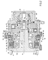
- Figure 1 shows a hydraulic piston motor radial, with fixed casing which comprises several parts, namely a first part 1A, called distribution cover, a second part 1 B, the inner periphery of which is wavy so as to form a reaction cam, and a third part 1C. These different parts are assembled by screws 2.
- the wavy cam is itself made in two parts, 4A and 4B, juxtaposed axially.
- the engine comprises a cylinder block 6 which is rotatably mounted relative about an axis of rotation 10 relative to the cam and which has a plurality of radial cylinders within which are sliding mounted radial pistons.
- the axes 13A of the cylinders 12A (axes arranged radially with respect to the axis of rotation 10) define a first radial plane PA, while the axes 13B of the cylinders of the second group 12B define a second radial plane PB distinct from the plane PA.
- the pistons 14A which slide in the cylinders 12A of the first group cooperate with the first part 4A of the cam, while the pistons 14B which slide in the cylinders 12B of the second group cooperate with the second part 4B of the cam.
- the cylinder block 6 rotates a shaft 5 which cooperates with it by grooves 7.
- the end of the shaft 5 opposite the distribution cover 1A carries an outlet plate 9 which, by studs 9 ', can be coupled to a wheel.
- Tree 5 is supported with respect to part 1C of the casing by means of bearing, for example tapered roller bearings 8A and 8B.
- the engine also has an internal distributor of fluid 16 which, by a system of pawns and notches 17, is made integral in rotation with the distribution cover 1A.
- the distributor 16 has an external axial face 18 stepped, cooperating with an internal axial face 19 stepped from distribution cover 1A. Between faces 18 and 19, are formed three gorges, respectively designated by the references 20, 21 and 22.
- the engine also has two main ducts, at know a main supply duct and a main duct exhaust. These main conduits are not in the section plane of Figure 1 but, to facilitate understanding, we indicated their positions with broken lines. So the first main duct 24 is permanently connected to the first groove 20, while the second main conduit 26 is permanently connected at the third groove 22.
- the second groove 21 may, depending on the position a displacement selector not shown in Figure 1, be connected to one or other of the grooves 20 and 22.
- the invention could be applied to other types of engines, for example to a non-radial piston engine disengageable or to an engine having, as the only group of cylinders, group 12A, or to an engine for which only two distribution grooves, respectively permanently connected to one and to the other of the main conduits, are formed between the dispenser and dispensing cover.
- Distribution ducts are made in the distributor and open into a radial distribution face 28 of the latter, pressing against a radial communication face 30 of the cylinder block.
- Distribution lines selectively connect the grooves 20, 21 and 22 on the distribution face.
- a distribution duct 31 has been shown which connects the groove 21 to the distribution face 28, and a conduit distribution 32 which connects the groove 22 to the distribution face.
- Each cylinder is associated with a cylinder duct, which allows it to be connected to the communication face 30 of the cylinder block, in order to put it in communication alternately with each of the distribution during rotation of the cylinder block relative to the cam.
- a cylinder duct 15B directly puts this cylinder in communication with the communication face 30.
- the communication of cylinder ducts 15A with the communication face 30 operates via a clutch selector 34.
- the selector 34 is formed by an axially movable drawer in a central bore 36 of the cylinder block.
- the selector is integral with the cylinder block with respect to the rotation about the axis 10. It has in fact a flange portion 34 'provided with holes in through which the screw rods 38 pass. These rods have, each, a threaded end portion 39A screwed into a thread of the cylinder block, and a smooth intermediate portion 39B, with which cooperates the drilling of the flange 34 'in which the rod is engaged considered.
- the selector 34 can slide relative to the screws 38.
- the external cylindrical face 34A of the selector 34 cooperating with the bore 36 of the cylinder block has as many conduits communication in the form of grooves 40 that the first group of cylinders comprises cylinders, each groove 40 being associated with a cylinder duct 15A.
- Each cylinder conduit 15A has one end connected to cylinder 12A and another end forming an orifice 15'A which is open in the bore 36 of the cylinder block. This orifice 15'A is in permanent communication with the groove of communication 40 associated with the cylinder duct 15A considered.
- Each 15A cylinder duct is associated with a passage distribution formed by a conduit 42 which has a first orifice 42A open in the bore 36 of the cylinder block and a second orifice 42B open on the communication face 30 of the cylinder block. As seen in Figure 1, this allows connect the distribution passage 42 to the distribution conduits such as conduit 32.
- the cylinder duct 15A and the distribution passage 42 therefore both open into bore 36 and, as can be seen in FIG. 1, this makes it possible to communicate the conduit of cylinder 15A with the distribution conduits when the selector 34 occupies its first position.
- the assembly formed by the conduit 15A, the communication groove 40 and the passage of distribution 42 forms in the first position of the selector 34, a duct substantially U-shaped, connected to the communication face 30 of the cylinder block.
- the communication groove 40 extends substantially axially and its length is sufficient to connect the orifices 15'A and 42A in the first position of the selector.
- the end of the distribution passage 42 located on the side of the cylinder 12A is closed by a 42C plug.
- An intercommunication annular groove 44 is made in the bore 36 of the cylinder block 6. Depending on the displacement of the selector, this groove 44 can be placed in communication with the communication grooves 40. Indeed, considered in the sense moving the selector from its first position to its second position, the orifice 42A, the orifice 15'A and the groove 44 are arranged one after another.
- the groove 44 allows, for a transient position intermediary of the selectors between its first and its second position, to communicate between them the cylinder ducts 15A in an isolated enclosure which it delimits.
- the selector 34 is permanently recalled towards its first position by a spring 54 disposed in a recess 56 of this selector and taking support on the shaft 5. It is controlled towards its second position by a control piston 58 cooperating with a control cylinder 60 which is formed in the cover of distribution 1A. This piston is moved by the fluid supply a control chamber 62.
- the decompression chamber 46 is connected to the enclosure internal 80 of the engine formed between the piston 58 and a bore internal 16A of the distributor by holes 78 made in the flange 34 'of selector 34.
- the leakage return pipe 48 is connected to this enclosure 80. It is also connected, by a section 48 ′, to the interior space of the motor 50 which is formed between the cylinder block and the cam. This 48 'section is fitted with a valve calibrated non-return 52 which allows only the circulation of fluid in the direction from space 50 to conduit 48, and only when the fluid pressure in space 50 is at least equal to one predetermined pressure.
- the motor stator includes the casing 1A, 1B, 1C, while that the rotor comprises the shaft 5 and the cylinder block 6.
- the braking system S of the rotor is now described by report to the stator. It includes annular brake discs arranged in a disk enclosure 100. The disks are distributed in a first series of discs 102 which are integral with the stator and in a second series of discs 104 which are integral of the rotor vis-à-vis the rotation of the latter relative to the stator.
- the discs 104 have, at their external peripheries, teeth 104 'which cooperate with grooves 105 produced on the internal periphery of part of the rotor formed in the example advantageous represented by an axial wall element 106 which is fixed to the plate 9 by screws 108 and which, from this plate, extends towards the distribution cover 1A so as to extend around a portion of part 1C of the motor housing and around of a portion of the tree 5.
- Part 1C indeed has a portion axial substantially in the form of a 1'C sleeve which is arranged on a intermediate radius between that of shaft 5 and that of the element of axial wall 106.
- the annular discs 102 of the first series are integral with this part 1C of the casing and, for this purpose, they present to their internal peripheries of the teeth 102 'which cooperate with splines 103 produced at the outer periphery of the sleeve 1'C.
- Braking is controlled using a piston device brake 108.
- the discs 102 and 104 are arranged between a axially fixed member 110 and the active face 108A of the device brake piston.
- the member 110 is constituted by an annular flange which is mounted on the 1'C sleeve and is held relative to the latter by means of a locking ring 112.
- the piston device 108 is moved towards the fixed element 110, the discs of the two series, which are interposed between the others are urged into frictional contact against each other other.
- the rotating discs are the discs external, integral with the axial wall element 106, while the fixed discs are the inner discs integral with the 1'C sleeve.
- the outer discs have an outer diameter greater than that of the interior discs.
- the brake has multiple effects and, to do this, the device piston 108 actually consists of two elementary pistons sliding relative to each other.
- the first elementary piston 114 is the one with the active face 108A and it cooperates with the first brake disc (in this case, a 102A disc of the first series), which is closest to this active face.
- the second elementary piston 116 cooperates with the elastic braking return means which, in the example shown, are constituted by a Belleville 118 spring washer.
- This spring 118 tends to bring the piston closer elastically elementary 116 of the brake discs.
- This elementary piston has an abutment face 116A which then comes to bear on a complementary stop face 114A of the first elementary piston, the face 114A being opposite to the face 108A.
- the elementary piston 116 tends to push back the piston elementary 114 towards the brake discs, so that the whole of the piston device 108 occupies its braking configuration.
- This braking system also has a chamber brake release hydraulic 120 which can be supplied with fluid under pressure by a brake release pipe 122 for, with an effort antagonistic to that of spring 118, move the elementary piston 116 away brake discs.
- the braking system also has a hydraulic brake chamber 124 which is likely to be supplied with pressurized fluid by a braking duct 126 to stress the first elementary piston 114 in its position of braking.
- Elementary piston 116 has a disc-shaped portion annular 116B and a sleeve portion 116C which, from the portion in the shape of an annular disc, extends towards the discs of brake. It is this sleeve 116C which carries the abutment face 116A.
- Rooms 120 and 124 are separated by a 1D part which, thanks to screws 128, is integral with part 1C of the casing.
- This part 1D is called the brake support.
- the separation between chambers 120 and 124 is produced by part 130 of part 1D in the form of a radial flange.
- Exhibit 1D also has a first axial extension in the form of a sleeve 132 which, from the part 130 extends towards the disk enclosure 100. It has a second axial extension 134 located on the side opposite to extension 132 and cooperating with screws 128.
- the supply of fluid to the brake release 120 allows, if the chamber 124 is not supplied with fluid, to provide brake release.
- Elastic return means of brake release tending to constantly push back the elementary piston 114 in the direction moving away from its active face 108A from the element fixed 110 can also be provided.
- the discs interiors 102 may, in the vicinity of their internal peripheries, have openings or notches 136 in which are arranged in the compression helical springs 138 taking support on the face 108A of the elementary piston 114 and on the face 110A of the part 110 which is turned towards this face 108A.
- the openings 136 also promote the circulation of the fluid cooling as we will see below.
- the brake line 126 is not completely in the section plane and we only represented the beginning of this duct which is adjacent to the braking chamber 124.
- the brake release pipe 122 is not located in the section plane and it is represented essentially in lines interrupted. It extends between a first end 122A which opens in the brake release chamber 120 and a second end 122B which is open outside the housing to be connected to a source of pressurized fluid.
- This brake release pipe likewise that the braking duct 126 is produced in part 1D.
- the rotor of the actual brake system includes part of the shaft 5, the plate 9 and the axial wall element 106, while the stator comprises the part 1C of the casing to which is fixed the 1D brake support.
- the braking system comprises a brake disc cooling device 102 and 104 by fluid circulation.
- a cooling duct 140 is permanently connected to the disk enclosure 100.
- This conduit 140 is placed in room 1D and it opens in the interior space the braking system in the region where the spring 118 is located, the end of the cooling duct being located between the part 1C and the second elementary piston 116.
- This duct cooling 140 is connected in bypass to the brake release 122.
- the duct 140 has a radial section 142 which is connected to an axial section 144 formed by a bore practiced in a region of part 134 of part 1D which is is radially projecting, this hole being closed on the outside of the part 1D using a plug 146.
- This section 144 makes it possible to connect the cooling duct 140 to the brake release duct 122.
- the hole 144 has a first tapped part 144A with which the plug 146 and a second part cooperates 144B of diameter smaller than that of the first part 144A, this part 144B having an intersection with the brake release pipe 122.
- a shoulder is formed between the parts 144A and 144B.
- This shoulder is used to have a restriction 148 constituted, for example, by a piece in the shape of a washer having an orifice calibrated and wedged against the aforementioned shoulder. Therefore, the amount of coolant that is taken from the pipe release brake 122 when the latter is supplied with fluid under pressure is limited.
- a calibrated valve 150 is arranged in the conduit of cooling 140.
- this conduit is connected to the conduit 122 through this calibrated valve, which does not allow the circulation of fluid between the brake release and cooling pipes that in the direction from the brake release line 122 to the release line cooling 140 and that when the fluid pressure in the brake release pipe 122, and therefore in the brake release chamber 120, is at least equal to a determined pressure conditioned by the calibration of the valve.
- the circuit when the engine is powered by a main pump of a hydrostatic closed circuit, the circuit includes also a booster pump.
- the brake release is supplied via this pump feeding, the feeding pressure being for example of the order of 20 bar, while the pressure delivered by the main pump can reach 300 to 400 bar.
- the brake release is obtained as soon as the fluid pressure in the brake release chamber reaches a brake release pressure, for example 10bar.
- the valve 150 can be calibrated at an intermediate pressure between the pressure of brake release and booster pressure, for example of the order of 12 to 14 bar.
- brake release line 122 can be powered by an emergency system, such as a hand pump.
- the pressure delivered by this pump is lower than the pressure of calibration of the valve 150, so that the brake release fluid is not consumed unnecessarily for cooling.
- the calibrated valve 150 is disposed after the restriction 148 in the direction from the brake release pipe 122 towards the cooling duct. Therefore, the flow of fluid passing through the valve is limited and it can be dimensioned accordingly.
- the disk enclosure 100 is closed vis-à-vis from the outside of the braking system by a seal 152 which realizes a sealed junction between the axial wall element 106 and the part 1D.
- the disk enclosure is in permanent communication with the part of the interior of the engine in which the 8B bearing of the shaft rotation support bearing by report to the housing. This bearing 8B is disposed between the periphery internal of the sleeve part 1'C of the part 1C and the shaft 5.
- That part of the engine interior space in which is the bearing 8B is called the bearing enclosure and is designated by the reference 50A. It is separate from part 50 the interior space of the engine between the cylinder block and the cam by a cooperation between the part 1C of the casing and the shaft 5.
- the part 1C of the casing has an axial face 154 which, in this case, is formed at the inner end of an annular wall element 156 of the part 1C of the casing which extends towards the shaft 5.
- a seal 158 provides a sealed connection between the face 154 and the axial face of the tree.
- the 50A bearing enclosure communicates with space 50 by a non-return valve 160 allowing only circulation of fluid in the direction from the disk enclosure 100 and enclosure 50A towards space 50.
- this valve 160 is arranged in the annular wall element 156. This space being connected to the leak return pipe 48 by the pipe section 48 ′ equipped with the valve 52 mentioned previously, the coolant can return to a tank without pressure. In the case of the above example, the setting pressure of this valve is around 2 bar.
- the annular wall element 156 which allows the separation of the enclosure 50A and the space 50 is disposed between the bearings 8A and 8B of the support bearing of the rotation of the shaft 5 relative to the casing.
- Coolant circulation is illustrated schematically in Figure 3 which shows only part of the disk enclosure 100.
- a brake release line 122 which is connected to the brake release chamber 120.
- Bypassed on this pipe is the cooling pipe 140.
- the restriction 148 and the calibrated valve 150 arranged on this conduct.
- the coolant flows in the section cooling line 142 to reach space formed between the second elementary piston 116 and part 1C of the casing, in the region in which the spring 118 is located.
- the fluid then flows between the axial faces opposite the part of sleeve 116C of the elementary piston 116 and of the part of 1'C sleeve of part 1C of the casing, until reaching the region in which the brake discs are located.
- the cooling duct 142 communicates with the disk enclosure 100 in a region of this enclosure which is near the axis of rotation 10 of the rotor relative to the stator. Indeed, the arrival of cooling fluid in the enclosure 100 takes place, as previously indicated, in the periphery region brake discs.
- On the inlet diameter of the cooling in the disk enclosure 100 are located only the interior discs 102 integral with the stator. Indeed, the inner free ends 104A of the discs 104 reach on a diameter greater than the maximum diameter of the openings 136 which are only practiced in the interior discs.
- brake release springs 138 are advantageously present in openings 136, this is not necessarily the case. What is springs are present or not, the openings constitute ways of coolant circulation. As indicated by arrows F, this fluid passes through the openings and can diffuse between the discs to completely bathe them.
- the openings 136 are advantageously offset angularly one compared to others (from one disc to another) when mounting discs. This further facilitates the diffusion of the coolant. across all of the discs since the openwork offset constitute axial baffles.
- the discs interiors 102 (those with the most internal peripheries close to the axis) are fixed in rotation since they are integral with the stator.
- the cooling fluid therefore enters the enclosure of disc 100 in a "calm” region of the latter and manages then in contact with the rotating discs to be diffused towards the exterior of the disk enclosure 100.
- the arrow F indicates the circulation of the coolant which enters the disk enclosure 100 in the bearing enclosure 50A which is in communication permanent with enclosure 100.
- This enclosure 50A does not communicate with the interior space 50 of the engine which is formed between the cylinder block and the cam only through the non-return valve 160 which only allows the circulation of the fluid in the direction going from the bearing enclosure 50A towards the interior space 50.
- the disk enclosure 100 communicates with the space 50 by through the check valve 160 which is arranged in a "connection conduit" between the enclosure 100 and the space 50.
- the cooling can flow in the 48 'section of the leakage return and then in the leakage return line 48 to be discharged into an external discharge vessel 49, for example a pressureless tank.
- pistons 14A of the first group of pistons of the engine of figure 1 are susceptible to be disengaged by being brought back into their respective cylinders towards the axis of rotation 10 of the motor.
- the presence of valves 160 and 52 previously mentioned makes it possible to reign in space inside 50 a pressure equal to the setting pressure of the valve 52, for example of the order of 2 bar. So this pressure, which is used to maintain the pistons 14A in their disengaged position, is ensured by the coolant coming from the disc enclosure 100.
- non-return valve 160 only allows the circulation of fluid in the direction from the enclosure 100 towards the interior space 50.
- these "non-return valve means” can also be achieved by a dynamic joint.
- a lip seal 161 can be interposed between the 50A bearing enclosure and the space interior 50 of the engine.
- the lip seal is for example arranged in part of annular flange 156 'of part 1C of the casing, flange annular shaped accordingly.
- This lip seal is arranged so as to allow the circulation of the fluid in the direction going from the enclosure 50A towards the interior space 50, when the fluid pressure in enclosure 50A is greater than that prevailing in space 50 ( Figure 5A). Otherwise, as shown in Figure 5B, lip seal 161 prevents flow of fluid in the direction from space 50 to enclosure 50A.
- a dynamic joint can be interposed between the disk enclosure 100 and the space 50 for allow only the circulation of the fluid in the direction going from enclosure 100 to space 50.
- Figures 2 and 4 show a variant affecting the coolant circulation.
- the disk enclosure 100 communicates with the decompression 46 by a connecting duct 200 which is formed in the shaft 5 of the engine.
- this decompression chamber is connected, by the holes 78 of the selector 34, to the internal enclosure 80 of the engine with which, in the disengaged position of the pistons of the first group, the 15A cylinder ducts corresponding to these pistons communicate.
- This internal enclosure 80 is itself connected to the conduit leakage return 48.
- the holes 78 which make the room communicate compensation 46 with the leakage return pipe 48 (by through the enclosure 80) can be equipped with means forming restriction.
- the presence of the coils of the spring 54 across these holes can act as such restrictions. In this way, a pressure drop is obtained on both sides holes 78.
- the engine in Figure 2 has pistons 14A of the first group which are disengageable. This time again, to keep them in the disengaged position, we use a fluid pressure prevailing in the interior space of the engine 50 delimited between the cylinder block 6 and the casing 1A, 1B, 1C.
- the disk enclosure 100 does not not communicate with space 50 but, via the chamber 46, with the leak return duct. Space 50 communicates via a tared non-return valve 252 with a pipe 248 'which is connected in bypass to the pipe of leakage return 48.
- the setting pressure of the valve 252 is for example of the order of 2 bar.
- This valve does not allow the circulation of fluid between space 50 and pipe 248 'only in the direction from space 50 towards this conduct. Under the effect of leaks between the cylinder block and the pistons, fluid pours into the interior space 50. Thanks to the presence of the tared non-return valve 252, we make sure that this fluid pressure is at least equal to the set pressure of the valve, to help maintain the pistons 14A in position disengaged when the selector 34 is put in the disengaged position.
- the coolant circulation pattern of the Figure 2 engine is shown in Figure 4.
- the cooling line 140 is connected in bypass on the brake release line 122.
- the coolant reaches the enclosure of 100 discs and is diffused towards the outside of this enclosure.
- the coolant flow is indicated by the arrows F '.
- the fluid cooling enters the decompression chamber 46 by the connecting conduit 200 (for example by having previously passed through the bearing enclosure 50A). This circulation between the disk enclosure 100 and the chamber 46 is carried out without any particular restriction.
- the coolant is connected to an external enclosure of discharge 49, via the leak return pipe 48. From its side, the interior space of the motor 50 is connected to the pipe leakage return 48 via an intermediate pipe 248 'on which is arranged the calibrated non-return valve 252.
- the dynamic seal or lip seal 161 of FIGS. 5A and 5B can also be provided in the variant of FIG. 2.
Landscapes
- Engineering & Computer Science (AREA)
- General Engineering & Computer Science (AREA)
- Mechanical Engineering (AREA)
- Transportation (AREA)
- Chemical & Material Sciences (AREA)
- Combustion & Propulsion (AREA)
- Braking Arrangements (AREA)
Abstract
Description
- La figure 1 montre, en coupe axiale, un moteur hydraulique à pistons radiaux équipé d'un système de freinage conforme à l'invention ;
- la figure 2 illustre une variante du moteur de la figure 1 ;
- les figures 3 et 4 montrent, selon deux variantes schématiques correspondant respectivement aux figures 1 et 2, le circuit de circulation du fluide de refroidissement, et
- les figures 5A et 5B montrent, selon une variante, une réalisation de la région V du moteur de la figure 1 ou de la région correspondante du moteur de la figure 2.
Claims (17)
- Système de freinage (S) d'un rotor (5, 9, 106) par rapport à un stator (1C, 1'C) comprenant des disques de frein disposés dans une enceinte de disques (100), ces disques étant répartis en une première série de disques (102) solidaires du stator (1'C) et une deuxième série de disques (104) solidaires du rotor (106) vis-à-vis de la rotation de ce dernier par rapport au stator, le système comprenant, en outre, un dispositif de piston de frein (108, 114, 116) susceptible d'être commandé entre une configuration de freinage dans laquelle une partie active (108A) de ce dispositif de piston coopère avec les disques de frein (102, 104) pour solliciter ces derniers en contact de freinage et une configuration de défreinage, le système comprenant encore des moyens de commande de ce dispositif de piston qui comportent des moyens de rappel élastique de freinage (118) sollicitant en permanence le dispositif de piston de frein vers sa configuration de freinage, une chambre de défreinage (120), distincte de l'enceinte de disques (100) et susceptible d'être alimentée en fluide sous pression par un conduit de défreinage (122) pour solliciter le dispositif de piston de frein (108, 114, 116) dans sa configuration de défreinage, et une chambre de freinage (124) susceptible d'être alimentée en fluide sous pression (126) pour solliciter le dispositif de piston de frein (108, 114, 116) vers sa configuration de freinage, le système de freinage comprenant, encore, un dispositif (140, 148) de refroidissement des disques de frein par circulation de fluide,
caractérisé en ce que le dispositif de refroidissement comporte, pour son alimentation en fluide de refroidissement, un conduit de refroidissement (140, 142), raccordé en dérivation sur le conduit de défreinage (122) et communiquant avec l'enceinte de disques (100), en ce que le conduit de refroidissement est réalisé dans une partie de carter (1D) du système de freinage et en ce qu'il comporte des moyens (148) pour limiter la quantité de fluide de refroidissement prélevée par le conduit de refroidissement (140) sur le conduit de défreinage (122). - Système selon la revendication 1, caractérisé en ce que le conduit de refroidissement (140, 142) est raccordé au conduit de défreinage (122) par un tronçon de raccordement (144), qui est pratiqué dans la partie de carter (1D) et qui présente une extrémité située sur la périphérie externe de ladite partie de carter et fermée par des moyens d'obturation amovibles.
- Système selon la revendication 1 ou 2, caractérisé en ce que le conduit de refroidissement (140) est raccordé au conduit de défreinage (122) par l'intermédiaire d'un dispositif (148) de limitation du débit du fluide dans ledit conduit de refroidissement (140).
- Système selon la revendication 3, caractérisé en ce que le conduit de refroidissement (140) est raccordé au conduit de défreinage (122) par l'intermédiaire d'une restriction (148).
- Système selon l'une quelconque des revendications 1 à 4, caractérisé en ce que le conduit de refroidissement (140) est raccordé au conduit de défreinage (122) par l'intermédiaire d'un clapet taré (150) n'autorisant la circulation du fluide du conduit de défreinage (122) vers ledit conduit de refroidissement (140) que lorsque la pression de fluide dans la chambre de défreinage (120) est au moins égale à une pression déterminée.
- Système selon les revendications 4 et 5, caractérisé en ce que le clapet taré (150) est disposé après la restriction (148) dans le sens allant du conduit de défreinage (122) vers le conduit de refroidissement (140).
- Système selon l'une quelconque des revendications 1 à 6, caractérisé en ce que le conduit de refroidissement (140) communique avec l'enceinte de disques (100) dans une région de ladite enceinte qui est voisine de l'axe de rotation (10) du rotor par rapport au stator.
- Système de frein selon l'une quelconque des revendications 1 à 7 caractérisé en ce que les disques (104) de la deuxième série, qui sont solidaires du rotor (5, 9, 106), présentent un diamètre extérieur supérieur au diamètre extérieur des disques (102) de la première série qui sont solidaires du stator (1C, 1'C), le rotor s'étendant au moins en partie (106) autour du stator (1'C) et chaque disque (104) de la deuxième série coopérant avec le rotor par sa périphérie externe (104', 105), tandis que chaque disque (102) de la première série coopère avec le stator par sa périphérie interne (102', 103).
- Système selon l'une quelconque des revendications 7 et 8, caractérisé en ce que des ajours (136) sont pratiqués dans des parties de disques de frein (102, 104) qui se trouvent dans la région de l'enceinte de disques (100) qui est voisine de l'axe (10) de rotation du rotor (5, 9, 106) par rapport au stator (1C, 1'C) et en ce que les ajours (136) des disques successivement disposés dans la direction axiale sont décalés angulairement les uns par rapport aux autres.
- Système selon l'une quelconque des revendications 1 à 9, caractérisé en ce que le rotor (5, 9, 106) est supporté à rotation par rapport au stator (1C, 1'C) par un palier comprenant au moins un roulement (8B) disposé dans une enceinte de roulement (50A) en communication permanente avec l'enceinte de disques (100).
- Moteur hydraulique comprenant un bloc-cylindres (6) tournant à pistons radiaux (14A, 14B), disposé dans un carter fixe (1A, 1B, 1C) présentant un organe de réaction (4A, 4B) pour les pistons, caractérisé en ce qu'il comporte un système de freinage (S) selon l'une quelconque des revendications 1 à 9, le rotor (5, 9, 106) et le stator (1C, 1'C) dudit système étant respectivement solidaires en rotation du bloc-cylindres (6) et du carter (1A, 1B, 1C) de ce moteur.
- Moteur selon la revendication 11, caractérisé en ce que l'enceinte de disques (100) est raccordée à l'espace intérieur (50) du moteur ménagé entre le carter (1A, 1B, 1C) et le bloc-cylindres (6) par l'intermédiaire de moyens de clapet anti-retour (160) autorisant seulement la circulation du fluide dans le sens allant de l'enceinte de disques (100) vers ledit espace intérieur (50).
- Moteur selon la revendication 11 ou 12, caractérisé en ce qu'il comporte au moins un groupe de pistons (14A) qui sont susceptibles d'être "débrayés" en étant ramenés dans leurs cylindres respectifs (12A) vers l'axe de rotation (10) du moteur, lesdits pistons étant susceptibles d'être maintenus dans cette position débrayée par la pression d'un fluide régnant dans l'espace intérieur (50) du moteur ménagé entre le carter (1A, 1B, 1C) et le bloc-cylindres (6), ledit espace intérieur étant relié au conduit de retour de fuites (48) par des moyens de clapet taré (52), et en ce que l'enceinte de disques (100) est raccordée à l'espace intérieur (50) du moteur de sorte que la pression servant à maintenir les pistons en position débrayée est assurée par le fluide provenant de l'enceinte de disques.
- Moteur selon la revendication 13, caractérisé en ce qu'il comporte des moyens (160) pour autoriser la circulation de fluide entre l'enceinte de disques (100) et l'espace intérieur (50) du moteur seulement dans le sens allant de ladite enceinte vers ledit espace.
- Moteur selon les revendications 13 et 14, caractérisé en ce qu'il comporte un clapet anti-retour (160) disposé dans le conduit de raccordement entre l'enceinte de disques (100) et l'espace intérieur du moteur (50).
- Moteur selon la revendication 11 ou 12, comportant un arbre moteur (5) solidaire en rotation du bloc-cylindres (6) et un conduit de retour de fuites (48, 248') qui relie une enceinte interne (46) du moteur à une enceinte extérieure de décharge (49), caractérisé en ce que l'enceinte de disques (100) communique avec ladite enceinte interne (46) par un conduit de raccordement (200) ménagé dans l'arbre moteur (5).
- Moteur selon la revendication 15, caractérisé en ce que l'enceinte de disques (100) est séparée de l'espace intérieur (50) du moteur ménagé entre le carter (1A, 1B, 1C) et le bloc-cylindres (6) par un joint dynamique (161) tel qu'un joint à lèvre disposé de façon à n'autoriser la circulation du fluide entre cette enceinte (100) et cet espace intérieur (50) que dans le sens allant de ladite enceinte vers ledit espace intérieur.
Applications Claiming Priority (2)
| Application Number | Priority Date | Filing Date | Title |
|---|---|---|---|
| FR9909718 | 1999-07-27 | ||
| FR9909718A FR2797008B1 (fr) | 1999-07-27 | 1999-07-27 | Systeme de freinage d'un rotor par rapport a un stator |
Publications (2)
| Publication Number | Publication Date |
|---|---|
| EP1072814A1 true EP1072814A1 (fr) | 2001-01-31 |
| EP1072814B1 EP1072814B1 (fr) | 2006-04-12 |
Family
ID=9548555
Family Applications (1)
| Application Number | Title | Priority Date | Filing Date |
|---|---|---|---|
| EP00401986A Expired - Lifetime EP1072814B1 (fr) | 1999-07-27 | 2000-07-10 | Système de freinage d'un rotor par rapport à un stator |
Country Status (4)
| Country | Link |
|---|---|
| US (1) | US6543222B1 (fr) |
| EP (1) | EP1072814B1 (fr) |
| DE (1) | DE60027233T2 (fr) |
| FR (1) | FR2797008B1 (fr) |
Cited By (8)
| Publication number | Priority date | Publication date | Assignee | Title |
|---|---|---|---|---|
| US6357558B1 (en) * | 1999-07-27 | 2002-03-19 | Poclain Hydraulics Industrie | Bearing device for supporting a wheel and equipped with braking means |
| WO2005001304A1 (fr) * | 2003-06-27 | 2005-01-06 | Lohmann & Stolterfoht Gmbh | Ensemble frein, en particulier pour entrainement de roue hydraulique |
| WO2013160145A3 (fr) * | 2012-04-28 | 2014-04-24 | Robert Bosch Gmbh | Moteur à pistons radiaux pourvu d'un frein |
| EP3269994A1 (fr) * | 2016-07-13 | 2018-01-17 | Poclain Hydraulics Industrie | Systeme de freinage ameliore pour machine hydraulique |
| WO2020193694A1 (fr) | 2019-03-27 | 2020-10-01 | Poclain Hydraulics Industrie | Machine hydraulique comportant un palier perfectionné |
| WO2021123549A1 (fr) * | 2019-12-20 | 2021-06-24 | Poclain Hydraulics Industrie | Machine hydraulique comprenant un organe de défreinage |
| WO2021191562A1 (fr) * | 2020-03-27 | 2021-09-30 | Poclain Hydraulics Industrie | Machine hydraulique comprenant un empilement de disques sollicités par un poussoir |
| WO2024251961A1 (fr) * | 2023-06-08 | 2024-12-12 | Poclain Hydraulics Industrie | Machine hydraulique tournante munie d'organes de freinage |
Families Citing this family (13)
| Publication number | Priority date | Publication date | Assignee | Title |
|---|---|---|---|---|
| JP2005042745A (ja) * | 2003-07-22 | 2005-02-17 | Toyota Industries Corp | 湿式ブレーキ |
| ITPD20070150A1 (it) * | 2007-04-23 | 2008-10-24 | Carraro Spa | Freno di soccorso |
| US8534431B2 (en) | 2010-07-21 | 2013-09-17 | Warn Industries, Inc. | Face tooth hydraulic piston brake |
| DE102011076581A1 (de) * | 2010-12-23 | 2012-06-28 | Robert Bosch Gmbh | Hydrostatische Kolbenmaschine mit Bremsvorrichtung |
| JP5948081B2 (ja) * | 2012-02-22 | 2016-07-06 | Kyb株式会社 | 液圧モータ |
| JP6350441B2 (ja) * | 2014-10-30 | 2018-07-04 | マツダ株式会社 | 変速機のブレーキ装置 |
| CN105221607A (zh) * | 2015-10-27 | 2016-01-06 | 龙岩文伍车桥制造有限公司 | 一种带驻车制动的湿式制动器 |
| DE102015222291B4 (de) | 2015-11-12 | 2019-09-12 | Robert Bosch Gmbh | Radialkolbenmaschine mit verdrehgesicherten Bremsmitteln |
| CN105299108B (zh) * | 2015-11-27 | 2017-09-12 | 重庆清平机械有限责任公司 | 一种减速器湿式常闭制动器 |
| FR3057845B1 (fr) * | 2016-10-25 | 2018-11-30 | Poclain Hydraulics Industrie | Systeme d'assistance a l'entrainement de vehicule comprenant un circuit hydraulique ouvert |
| EP4208639B1 (fr) * | 2020-12-16 | 2024-01-17 | Danfoss Power Solutions (Jiangsu) Co., Ltd. | Unité hydrostatique de piston radial |
| US12497943B2 (en) * | 2021-12-16 | 2025-12-16 | Danfoss A/S | Brake mechanism for a radial piston unit |
| IT202300007668A1 (it) * | 2023-04-19 | 2024-10-19 | Cnh Ind Italia Spa | Assieme di frenatura per un veicolo da lavoro e metodo di controllo della lubrificazione di un assieme di frenatura |
Citations (2)
| Publication number | Priority date | Publication date | Assignee | Title |
|---|---|---|---|---|
| EP0913304A2 (fr) * | 1997-10-22 | 1999-05-06 | Carraro S.P.A. | Unité integrée pour freinage de stationnement et de service de parties rotatives |
| US5911292A (en) * | 1996-05-04 | 1999-06-15 | Schuler Pressen Gmbh & Co. | High efficiency torque transmission arrangement with radial coolant flow |
-
1999
- 1999-07-27 FR FR9909718A patent/FR2797008B1/fr not_active Expired - Lifetime
-
2000
- 2000-07-10 DE DE60027233T patent/DE60027233T2/de not_active Expired - Lifetime
- 2000-07-10 EP EP00401986A patent/EP1072814B1/fr not_active Expired - Lifetime
- 2000-07-25 US US09/624,823 patent/US6543222B1/en not_active Expired - Lifetime
Patent Citations (2)
| Publication number | Priority date | Publication date | Assignee | Title |
|---|---|---|---|---|
| US5911292A (en) * | 1996-05-04 | 1999-06-15 | Schuler Pressen Gmbh & Co. | High efficiency torque transmission arrangement with radial coolant flow |
| EP0913304A2 (fr) * | 1997-10-22 | 1999-05-06 | Carraro S.P.A. | Unité integrée pour freinage de stationnement et de service de parties rotatives |
Cited By (19)
| Publication number | Priority date | Publication date | Assignee | Title |
|---|---|---|---|---|
| US6357558B1 (en) * | 1999-07-27 | 2002-03-19 | Poclain Hydraulics Industrie | Bearing device for supporting a wheel and equipped with braking means |
| WO2005001304A1 (fr) * | 2003-06-27 | 2005-01-06 | Lohmann & Stolterfoht Gmbh | Ensemble frein, en particulier pour entrainement de roue hydraulique |
| US7380643B2 (en) | 2003-06-27 | 2008-06-03 | Lohmann & Stolterfoht Gmbh | Brake assembly, particularly for a hydraulic wheel drive |
| EP2841763B1 (fr) | 2012-04-28 | 2018-05-23 | Robert Bosch GmbH | Moteur à pistons radiaux pourvu d'un frein |
| WO2013160145A3 (fr) * | 2012-04-28 | 2014-04-24 | Robert Bosch Gmbh | Moteur à pistons radiaux pourvu d'un frein |
| US9777573B2 (en) | 2012-04-28 | 2017-10-03 | Robert Bosch Gmbh | Radial piston engine with brake |
| US11067144B2 (en) | 2016-07-13 | 2021-07-20 | Poclain Hydraulics Industrie | Braking system for a hydraulic machine |
| FR3054010A1 (fr) * | 2016-07-13 | 2018-01-19 | Poclain Hydraulics Ind | Systeme de freinage ameliore pour machine hydraulique |
| EP3269994A1 (fr) * | 2016-07-13 | 2018-01-17 | Poclain Hydraulics Industrie | Systeme de freinage ameliore pour machine hydraulique |
| WO2020193694A1 (fr) | 2019-03-27 | 2020-10-01 | Poclain Hydraulics Industrie | Machine hydraulique comportant un palier perfectionné |
| FR3094425A1 (fr) | 2019-03-27 | 2020-10-02 | Poclain Hydraulics Industrie | Machine hydraulique comportant un palier perfectionné |
| US12025111B2 (en) | 2019-03-27 | 2024-07-02 | Porclain Hydraulics Industrie | Hydraulic machine comprising an improved bearing |
| WO2021123549A1 (fr) * | 2019-12-20 | 2021-06-24 | Poclain Hydraulics Industrie | Machine hydraulique comprenant un organe de défreinage |
| FR3105309A1 (fr) * | 2019-12-20 | 2021-06-25 | Poclain Hydraulics Industrie | Machine hydraulique comprenant un organe de défreinage |
| WO2021191562A1 (fr) * | 2020-03-27 | 2021-09-30 | Poclain Hydraulics Industrie | Machine hydraulique comprenant un empilement de disques sollicités par un poussoir |
| FR3108693A1 (fr) * | 2020-03-27 | 2021-10-01 | Poclain Hydraulics Industrie | Machine hydraulique comprenant un empilement de disques sollicités par un poussoir |
| CN115667751A (zh) * | 2020-03-27 | 2023-01-31 | 波克兰液压工业设备公司 | 包括由推杆作用的盘件的叠堆的液压机器 |
| WO2024251961A1 (fr) * | 2023-06-08 | 2024-12-12 | Poclain Hydraulics Industrie | Machine hydraulique tournante munie d'organes de freinage |
| FR3149657A1 (fr) * | 2023-06-08 | 2024-12-13 | Poclain Hydraulics Industrie | Machine hydraulique tournante munie d'organes de freinage |
Also Published As
| Publication number | Publication date |
|---|---|
| FR2797008B1 (fr) | 2001-10-19 |
| FR2797008A1 (fr) | 2001-02-02 |
| US6543222B1 (en) | 2003-04-08 |
| EP1072814B1 (fr) | 2006-04-12 |
| DE60027233D1 (de) | 2006-05-24 |
| DE60027233T2 (de) | 2007-02-01 |
Similar Documents
| Publication | Publication Date | Title |
|---|---|---|
| EP1072814B1 (fr) | Système de freinage d'un rotor par rapport à un stator | |
| EP1750967B1 (fr) | Element de transmission a embrayages humides pour chaine de traction hybride de vehicule automobile, et vehicule automobile equipe d'un tel element | |
| FR2796886A1 (fr) | Dispositif de palier de support d'une roue equipe de moyens de freinage | |
| BE1006281A3 (fr) | Changement de vitesse a organe de transmission sur flasques coniques. | |
| EP0341137B1 (fr) | Dispositif à palier magnétique et palier auxiliaire pour arbre tournant | |
| EP3269994B1 (fr) | Systeme de freinage ameliore pour machine hydraulique | |
| FR2727733A1 (fr) | Capteur de couple, notamment pour transmissions de vehicules | |
| EP1154170B1 (fr) | Système de freinage d'un rotor par rapport à un stator | |
| FR2517003A1 (fr) | Moyeu de roue a reducteur et frein integre | |
| EP2491277B1 (fr) | Dispositif de transmission hydrostatique permettant un freinage ameliore | |
| EP4012213B1 (fr) | Roue libre munie d'une barriere de lubrification a ouverture variable | |
| EP1072791B1 (fr) | Moteur hydraulique a pistons radiaux et a selecteur de debrayage unique | |
| FR2911928A1 (fr) | Moteur hydraulique a pistons. | |
| FR2821644A1 (fr) | Dispositif de commande de calage de soupapes | |
| EP3268638B1 (fr) | Dispositif distributeur et limiteur de pression, notamment pour un dispositif d'assistance hydraulique sur véhicule et véhicule ainsi équipé | |
| EP0459840B1 (fr) | Dispositif de commande d'un vérin hydraulique à double effet | |
| FR3043147A1 (fr) | Machine hydraulique a deux cylindrees et a valve de securite | |
| BE1009541A6 (fr) | Regulateur de debit. | |
| FR2778703A1 (fr) | Circuit de fluide hydraulique ayant un moteur hydraulique et un selecteur a trois positions pour selectionner la circulation de fluide | |
| EP0381716A1 (fr) | Dispositif de commande d'embrayage. | |
| EP0428192A2 (fr) | Variateur hydrostatique de vitesse à pistons radiaux | |
| EP0021259A1 (fr) | Dispositif de commande de pontage d'un convertisseur de couple hydrodynamique | |
| FR2716506A1 (fr) | Embrayage. | |
| FR3021078A1 (fr) | Systeme de freinage dote d'un moyen de refroidissement | |
| FR2736124A1 (fr) | Ensemble hydrostatique a patinage controle |
Legal Events
| Date | Code | Title | Description |
|---|---|---|---|
| PUAI | Public reference made under article 153(3) epc to a published international application that has entered the european phase |
Free format text: ORIGINAL CODE: 0009012 |
|
| AK | Designated contracting states |
Kind code of ref document: A1 Designated state(s): DE FR GB |
|
| AX | Request for extension of the european patent |
Free format text: AL;LT;LV;MK;RO;SI |
|
| 17P | Request for examination filed |
Effective date: 20010607 |
|
| AKX | Designation fees paid |
Free format text: DE FR GB |
|
| GRAP | Despatch of communication of intention to grant a patent |
Free format text: ORIGINAL CODE: EPIDOSNIGR1 |
|
| GRAS | Grant fee paid |
Free format text: ORIGINAL CODE: EPIDOSNIGR3 |
|
| GRAA | (expected) grant |
Free format text: ORIGINAL CODE: 0009210 |
|
| AK | Designated contracting states |
Kind code of ref document: B1 Designated state(s): DE FR GB |
|
| REG | Reference to a national code |
Ref country code: GB Ref legal event code: FG4D Free format text: NOT ENGLISH |
|
| REF | Corresponds to: |
Ref document number: 60027233 Country of ref document: DE Date of ref document: 20060524 Kind code of ref document: P |
|
| GBT | Gb: translation of ep patent filed (gb section 77(6)(a)/1977) |
Effective date: 20060628 |
|
| PLBE | No opposition filed within time limit |
Free format text: ORIGINAL CODE: 0009261 |
|
| STAA | Information on the status of an ep patent application or granted ep patent |
Free format text: STATUS: NO OPPOSITION FILED WITHIN TIME LIMIT |
|
| 26N | No opposition filed |
Effective date: 20070115 |
|
| REG | Reference to a national code |
Ref country code: FR Ref legal event code: PLFP Year of fee payment: 17 |
|
| REG | Reference to a national code |
Ref country code: FR Ref legal event code: PLFP Year of fee payment: 18 |
|
| PGFP | Annual fee paid to national office [announced via postgrant information from national office to epo] |
Ref country code: DE Payment date: 20170713 Year of fee payment: 18 Ref country code: GB Payment date: 20170721 Year of fee payment: 18 |
|
| REG | Reference to a national code |
Ref country code: FR Ref legal event code: PLFP Year of fee payment: 19 |
|
| REG | Reference to a national code |
Ref country code: DE Ref legal event code: R119 Ref document number: 60027233 Country of ref document: DE |
|
| GBPC | Gb: european patent ceased through non-payment of renewal fee |
Effective date: 20180710 |
|
| PG25 | Lapsed in a contracting state [announced via postgrant information from national office to epo] |
Ref country code: GB Free format text: LAPSE BECAUSE OF NON-PAYMENT OF DUE FEES Effective date: 20180710 Ref country code: DE Free format text: LAPSE BECAUSE OF NON-PAYMENT OF DUE FEES Effective date: 20190201 |
|
| PGFP | Annual fee paid to national office [announced via postgrant information from national office to epo] |
Ref country code: FR Payment date: 20190724 Year of fee payment: 20 |