EP1072846A2 - Convecteur pour plafond - Google Patents
Convecteur pour plafond Download PDFInfo
- Publication number
- EP1072846A2 EP1072846A2 EP00114735A EP00114735A EP1072846A2 EP 1072846 A2 EP1072846 A2 EP 1072846A2 EP 00114735 A EP00114735 A EP 00114735A EP 00114735 A EP00114735 A EP 00114735A EP 1072846 A2 EP1072846 A2 EP 1072846A2
- Authority
- EP
- European Patent Office
- Prior art keywords
- heat exchanger
- ceiling
- ceiling convector
- air
- inflow area
- Prior art date
- Legal status (The legal status is an assumption and is not a legal conclusion. Google has not performed a legal analysis and makes no representation as to the accuracy of the status listed.)
- Withdrawn
Links
Images


Classifications
-
- F—MECHANICAL ENGINEERING; LIGHTING; HEATING; WEAPONS; BLASTING
- F24—HEATING; RANGES; VENTILATING
- F24F—AIR-CONDITIONING; AIR-HUMIDIFICATION; VENTILATION; USE OF AIR CURRENTS FOR SCREENING
- F24F1/00—Room units for air-conditioning, e.g. separate or self-contained units or units receiving primary air from a central station
- F24F1/01—Room units for air-conditioning, e.g. separate or self-contained units or units receiving primary air from a central station in which secondary air is induced by injector action of the primary air
-
- F—MECHANICAL ENGINEERING; LIGHTING; HEATING; WEAPONS; BLASTING
- F24—HEATING; RANGES; VENTILATING
- F24F—AIR-CONDITIONING; AIR-HUMIDIFICATION; VENTILATION; USE OF AIR CURRENTS FOR SCREENING
- F24F1/00—Room units for air-conditioning, e.g. separate or self-contained units or units receiving primary air from a central station
- F24F1/0007—Indoor units, e.g. fan coil units
- F24F1/0043—Indoor units, e.g. fan coil units characterised by mounting arrangements
- F24F1/0047—Indoor units, e.g. fan coil units characterised by mounting arrangements mounted in the ceiling or at the ceiling
-
- F—MECHANICAL ENGINEERING; LIGHTING; HEATING; WEAPONS; BLASTING
- F24—HEATING; RANGES; VENTILATING
- F24F—AIR-CONDITIONING; AIR-HUMIDIFICATION; VENTILATION; USE OF AIR CURRENTS FOR SCREENING
- F24F1/00—Room units for air-conditioning, e.g. separate or self-contained units or units receiving primary air from a central station
- F24F1/0007—Indoor units, e.g. fan coil units
- F24F1/0059—Indoor units, e.g. fan coil units characterised by heat exchangers
- F24F1/0063—Indoor units, e.g. fan coil units characterised by heat exchangers by the mounting or arrangement of the heat exchangers
Definitions
- the invention relates to a ceiling convector with lines that run from a heat transfer medium are flowable, and thus heat-conductive coupled, lamellar Heat exchanger elements that are arranged in parallel to each other at least form a heat exchanger package, being between two heat exchanger elements there is an air gap for the passage of air that the Flows through the heat exchanger package from top to bottom and can be cooled or is heatable.
- Such ceiling convectors are generally known and are suitable for both Installation in suspended ceiling constructions as well as for separate free suspension on a building ceiling. While in the latter arrangement with sufficient a large distance from the ceiling of the building automatically provides a sufficient flow area for the air to be tempered, this is when installed in a suspended ceiling much more difficult to reach. With known ceiling convectors The air to be tempered is therefore used in suspended ceiling constructions often through shadow gaps at the edges of the ceiling in the air gap between the suspended ceiling and the actual building ceiling guided. Apart from the long-distance and therefore expensive Air flow, this principle also has the disadvantage that the area above the ceiling convector for cleaning or revision purposes practically not more can be achieved.
- the invention has for its object to propose a ceiling convector, sufficient for installation in suspended ceiling constructions has a large inflow area, the construction being simple and also a allow later access to the top of the heat exchanger package should.
- the inflow area can be enlarged, so that that of the Convector power increases.
- the supply of centrally arranged Heat exchanger packages over lateral inflow areas are possible.
- the inflow area if necessary, can also be provided with heat exchanger elements can, so that the gap between two heat exchanger packages possibly can be closed completely, so that a continuous large heat exchanger package arises.
- Such a type of convector is particularly suitable for the Use in a form suspended from the ceiling, as the inflow in this Case can be done laterally.
- the ceiling convector and a ceiling convector without an integrated inflow area can be adjusted the modular principle of identical components and on the same manufacturing systems to produce. As a result, the manufacturing costs for the invention Ceiling convector compared to a completely independent construction as an alternative to a convector for free hanging use significantly reduced.
- a development of the invention is that at a distance below the Ceiling convector is a horizontally extending perforated plate, of which vertical flow bulkheads that extend to the bottom of a heat exchanger package and the inflow area from an outflow area separate.
- the performance of the Ceiling convector can be increased due to forced convection.
- this configuration offers Benefits. Forced convection is particularly important if the ceiling convector is also to be used for heating, because in this case a high penetration depth of the heated supply air is required to also lower Comfortable tempering of areas of the room.
- the Blower blocked only part of the cross section of the inflow area.
- the subject to change Part of the inflow area should be dimensioned so that this is can establish sufficient flow due to natural convection.
- the functionality of the ceiling convector can be increased if outside air in the Inflow area and / or the outflow area can be introduced.
- the Outside air in the inflow area can be used with the help of the heat exchanger package cool down or warm up.
- the outside air should flow in the direction of flow of the air flow to which it can be mixed.
- a tube perforated on one side over its circumference For example with the help of a tube perforated on one side over its circumference.
- one Heat exchanger package conditioned air can be supplied, the associated Inflow area is closed. In this way the ceiling convector can be used even when retrofitted in an existing air conditioning system integrate.
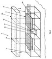
- a ceiling convector 1 shown in Fig. 1 has a housing 2, which consists of two long side walls 3, two end walls 4 and one made of perforated sheet metal Soil 5 exists and is generally rectangular.
- two heat exchanger packages 6 are arranged, each of a plurality of parallel, lamellar heat exchanger elements 7 assembled are.
- the heat exchanger elements 7 each have two bores on, which are penetrated by two rigid lines 8.
- These lines are 8 a heat transfer medium, in particular water, can flow through.
- the two lines 8 are connected together, so that one strand as forward and another strand as return for the Water serves.
- Two further inflow areas 11 and 12 are located immediately to the side of the heat exchanger packages 6 and are except for sections the lines 8 also free of internals.
- the ceiling convector 1 shown in Fig. 1 is used to cool the air in one Space, the floor consisting of a perforated plate 5 flush with a suspended closed ceiling 13 completes.
- the actual building ceiling, to which the ceiling convector 1 and the lines 8 are fastened is not shown in FIG. 1 shown.
- the cooled air emerges from the floor 5 of the ceiling convector 1 essentially vertical while the (in a different plane) Air flowing in from below in the edge regions of the base 5 also has a lateral one Has flow component.
- FIG. 3 shows how the inflow of air through three inflow regions 10, 11 and 12, one of which takes place between the two heat exchanger packages 6 and the other two are arranged laterally next to a heat exchanger package 6 are.
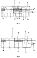
- the ceiling convector 1 'according to FIG. 4 differs from that in FIGS. 1 to 3 ceiling convector 1 shown only in that in the inflow region 10th a blower 16 is arranged in a funnel-shaped blower housing 17 is.
- the blower 16 is a widespread and due to its robustness proven cross flow fan.
- the blower housing 17 is like this dimensioned so that it covers only a part of the cross section of the inflow region 10, so that operation of the ceiling convector 1 'solely due to the natural Convection is also possible when the fan 16 is switched off.
- the ceiling convector 1 ' is provided with a cover 18, which is on from above the housing 2 can be fitted and is made of closed sheet metal on all sides.
- the Cover 18 is provided with two flow bulkheads 19 which have a short-circuit flow in the horizontal direction above the heat exchanger packages 6 immediately to the lateral inflow areas 11 and 12 prevent.
- the flow conditions which arise during operation of the fan 16 are also shown 5 illustrated.
- the inflow of air over the inflow area 10 takes place both by the fan 16 and laterally past it.
- the total air volume flow through the ceiling convector 1 ' is opposite one Design based solely on natural convection (Fig. 1), significantly increased, so that the transferable cooling or heating capacity is also noticeably increased.
- 5 can also be seen that the flow bulkheads 19 of the cover 18 for a deflection of the flowing above the heat exchanger packages 6 Provide air down and thus a short circuit flow towards the side Prevent inflow areas 11 and 12.
- the alternative ceiling convector 1 ′′ shown in FIG. 6 has an inflow pipe 20 provided, on the one hand the lateral inflow area 12 and the outflow area 14 penetrates below a heat exchanger package.
- the inflow pipe 20 through which outside air is the possibly has been conditioned beforehand, is eligible, with perforations pointing upwards 21 provided while the perforations 22 within the outflow area 14 after point below.
- perforations pointing upwards 21 provided while the perforations 22 within the outflow area 14 after point below.
- the ceiling convector 1 '' 'shown in FIG. 7 it is designed as a perforated plate Soil 5 over the cross section of the lateral inflow region 12 with the aid of a Sheet 23 closed.
- the heat exchanger package 6 is supplied via a connection line 24, into which preconditioned with the aid of an air conditioning system Air can be fed.
Landscapes
- Engineering & Computer Science (AREA)
- Chemical & Material Sciences (AREA)
- Combustion & Propulsion (AREA)
- Mechanical Engineering (AREA)
- General Engineering & Computer Science (AREA)
- Physics & Mathematics (AREA)
- Thermal Sciences (AREA)
- Heat-Exchange Devices With Radiators And Conduit Assemblies (AREA)
- Cooling Or The Like Of Electrical Apparatus (AREA)
Applications Claiming Priority (2)
| Application Number | Priority Date | Filing Date | Title |
|---|---|---|---|
| DE19934886 | 1999-07-24 | ||
| DE19934886A DE19934886C1 (de) | 1999-07-24 | 1999-07-24 | Deckenkonvektor |
Publications (2)
| Publication Number | Publication Date |
|---|---|
| EP1072846A2 true EP1072846A2 (fr) | 2001-01-31 |
| EP1072846A3 EP1072846A3 (fr) | 2002-04-17 |
Family
ID=7916001
Family Applications (1)
| Application Number | Title | Priority Date | Filing Date |
|---|---|---|---|
| EP00114735A Withdrawn EP1072846A3 (fr) | 1999-07-24 | 2000-07-08 | Convecteur pour plafond |
Country Status (2)
| Country | Link |
|---|---|
| EP (1) | EP1072846A3 (fr) |
| DE (1) | DE19934886C1 (fr) |
Cited By (2)
| Publication number | Priority date | Publication date | Assignee | Title |
|---|---|---|---|---|
| EP4036485A4 (fr) * | 2020-12-11 | 2023-01-04 | Guangdong Midea White Home Appliance Technology Innovation Center Co., Ltd. | Unité intérieure de climatiseur et climatiseur |
| FR3129712A1 (fr) * | 2021-11-30 | 2023-06-02 | Pi-Thermie | Dispositif émetteur de chaleur ou de froid à convection forcée et système de chauffage ou de rafraichissement intégrant ce dispositif |
Families Citing this family (1)
| Publication number | Priority date | Publication date | Assignee | Title |
|---|---|---|---|---|
| DE102010047922A1 (de) * | 2010-10-08 | 2012-04-12 | Martin Schönhammer | Lüftungsinstallation |
Family Cites Families (11)
| Publication number | Priority date | Publication date | Assignee | Title |
|---|---|---|---|---|
| SE462237B (sv) * | 1985-09-10 | 1990-05-21 | Flaekt Ab | Anordning vid ett foer en uppsaettning elektroniska utrustningar avsett kylelement |
| SE461172B (sv) * | 1987-08-31 | 1990-01-15 | Novenco Ab | Vaerme- eller kylanordning att anbringas vid tak |
| DE3809060A1 (de) * | 1988-03-18 | 1989-09-28 | Timmer Ingbuero Gmbh | System zum temperieren von raeumen eines gebaeudes |
| ATE122776T1 (de) * | 1991-04-12 | 1995-06-15 | Kessler & Luch Gmbh | Anordnung zum abführen von wärmelasten. |
| DE4216136A1 (de) * | 1992-05-15 | 1993-11-18 | Koester Helmut | Kühldecken nach Konvektionsprinzip II |
| DE4308502A1 (de) * | 1992-04-21 | 1993-12-09 | Schako Metallwarenfabrik | Decke |
| SE9301237L (sv) * | 1993-04-14 | 1994-10-15 | Farex As | Anordning för kylning av rumsluft |
| DE9400738U1 (de) * | 1994-01-18 | 1994-03-10 | H. Krantz-Tkt Gmbh, 51465 Bergisch Gladbach | Konvektives Kühlelement |
| DE4406343C2 (de) * | 1994-02-26 | 2000-08-10 | Bree Hartmut | Kühlelement zur Raumkühlung |
| EP0733866A3 (fr) * | 1995-03-21 | 1997-04-16 | Giacomini Services And Enginee | Plafond pour chauffage ou pour refroidissement |
| DE19525945C2 (de) * | 1995-07-18 | 2000-08-17 | Joachim Griepentrog | Verfahren und Vorrichtung zur Erzeugung behaglicher Raumluftzustände |
-
1999
- 1999-07-24 DE DE19934886A patent/DE19934886C1/de not_active Expired - Fee Related
-
2000
- 2000-07-08 EP EP00114735A patent/EP1072846A3/fr not_active Withdrawn
Cited By (4)
| Publication number | Priority date | Publication date | Assignee | Title |
|---|---|---|---|---|
| EP4036485A4 (fr) * | 2020-12-11 | 2023-01-04 | Guangdong Midea White Home Appliance Technology Innovation Center Co., Ltd. | Unité intérieure de climatiseur et climatiseur |
| US12085288B2 (en) | 2020-12-11 | 2024-09-10 | Guangdong Midea White Home Appliance Technology Innovation Center Co., Ltd. | Air conditioner indoor unit and air conditioner |
| FR3129712A1 (fr) * | 2021-11-30 | 2023-06-02 | Pi-Thermie | Dispositif émetteur de chaleur ou de froid à convection forcée et système de chauffage ou de rafraichissement intégrant ce dispositif |
| WO2023099555A1 (fr) * | 2021-11-30 | 2023-06-08 | Pi-Thermie | Dispositif émetteur de chaleur ou de froid et système de chauffage ou de rafraichissement intégrant ce dispositif |
Also Published As
| Publication number | Publication date |
|---|---|
| DE19934886C1 (de) | 2001-03-01 |
| EP1072846A3 (fr) | 2002-04-17 |
Similar Documents
| Publication | Publication Date | Title |
|---|---|---|
| DE3874344T2 (de) | Verfahren zur lueftung und lueftungsanlage. | |
| EP1586823B1 (fr) | Plafond, en particulier plafond réfrigérant ou chauffant | |
| DE69416827T2 (de) | Vorrichtung zum kühlen von raumluft | |
| DE2328186C2 (de) | Induktionsgerät | |
| DE3616733C2 (fr) | ||
| EP1072846A2 (fr) | Convecteur pour plafond | |
| EP0475261A1 (fr) | Radiateur | |
| EP0026443B1 (fr) | Dispositif pour évacuer la chaleur perdue de boîtiers d'appareillage électronique encastrés dans un bâti d'armoire | |
| WO1983000544A1 (fr) | Installation pour temperer une piece | |
| DE3029298C2 (de) | Raumheizgerät für Kleinräume | |
| EP3587943B1 (fr) | Dispositif d'aération et de mise en température d'une pièce dans un bâtiment | |
| EP2051017A2 (fr) | Dispositif de climatisation de pièces | |
| CH657693A5 (de) | Lueftungsvorrichtung fuer einen raum mit zwei getrennten stroemungswegen zur belueftung und entlueftung. | |
| DE3322075C2 (de) | Gerät zum Temperieren der Luft innerhalb eines Raumes | |
| DE69108361T2 (de) | Wärmetauschanordnung. | |
| EP3477212B1 (fr) | Dispositif de distribution d'air ainsi que procédé d'aération d'une pièce | |
| EP0972998B1 (fr) | Ensemble collecteur pour radiateurs de chauffage ou de réfrigeration | |
| EP0893655B1 (fr) | Unité de chauffage pour chauffage à air chaud pour églises | |
| DE69001073T2 (de) | Klimavorrichtung für ein gebäude. | |
| EP0651216A1 (fr) | Réfrigérateur ou congélateur ménager | |
| EP0374527A2 (fr) | Système de distribution d'air | |
| EP1243870A2 (fr) | Radiateur | |
| EP0392150B1 (fr) | Four de boulangerie à circulation de gaz de chauffage | |
| DE2110781A1 (de) | Vorrichtung zum Heizen oder Kuehlen von Raeumen | |
| DE2630300A1 (de) | Konvektor-waermestrahler in blockkonstruktion |
Legal Events
| Date | Code | Title | Description |
|---|---|---|---|
| PUAI | Public reference made under article 153(3) epc to a published international application that has entered the european phase |
Free format text: ORIGINAL CODE: 0009012 |
|
| AK | Designated contracting states |
Kind code of ref document: A2 Designated state(s): AT BE CH CY DE DK ES FI FR GB GR IE IT LI LU MC NL PT SE |
|
| AX | Request for extension of the european patent |
Free format text: AL;LT;LV;MK;RO;SI |
|
| PUAL | Search report despatched |
Free format text: ORIGINAL CODE: 0009013 |
|
| AK | Designated contracting states |
Kind code of ref document: A3 Designated state(s): AT BE CH CY DE DK ES FI FR GB GR IE IT LI LU MC NL PT SE |
|
| AX | Request for extension of the european patent |
Free format text: AL;LT;LV;MK;RO;SI |
|
| AKX | Designation fees paid | ||
| REG | Reference to a national code |
Ref country code: DE Ref legal event code: 8566 |
|
| STAA | Information on the status of an ep patent application or granted ep patent |
Free format text: STATUS: THE APPLICATION IS DEEMED TO BE WITHDRAWN |
|
| 18D | Application deemed to be withdrawn |
Effective date: 20021018 |