EP1072885A2 - Appareil pour la mesure de l'humidité de céréales - Google Patents
Appareil pour la mesure de l'humidité de céréales Download PDFInfo
- Publication number
- EP1072885A2 EP1072885A2 EP00113310A EP00113310A EP1072885A2 EP 1072885 A2 EP1072885 A2 EP 1072885A2 EP 00113310 A EP00113310 A EP 00113310A EP 00113310 A EP00113310 A EP 00113310A EP 1072885 A2 EP1072885 A2 EP 1072885A2
- Authority
- EP
- European Patent Office
- Prior art keywords
- moisture
- resonant circuit
- voltage
- frequency
- resonance
- Prior art date
- Legal status (The legal status is an assumption and is not a legal conclusion. Google has not performed a legal analysis and makes no representation as to the accuracy of the status listed.)
- Withdrawn
Links
- 235000013339 cereals Nutrition 0.000 title description 26
- 239000003990 capacitor Substances 0.000 claims abstract description 30
- 238000000034 method Methods 0.000 claims abstract description 3
- 238000005259 measurement Methods 0.000 claims description 25
- 239000000463 material Substances 0.000 claims description 6
- 241001124569 Lycaenidae Species 0.000 claims description 4
- 239000004459 forage Substances 0.000 claims description 2
- 238000001514 detection method Methods 0.000 abstract description 2
- 239000002184 metal Substances 0.000 description 14
- 230000001419 dependent effect Effects 0.000 description 9
- 230000003071 parasitic effect Effects 0.000 description 5
- 238000011156 evaluation Methods 0.000 description 4
- 230000010363 phase shift Effects 0.000 description 3
- 239000010902 straw Substances 0.000 description 3
- 238000004140 cleaning Methods 0.000 description 2
- 238000010586 diagram Methods 0.000 description 2
- 238000005516 engineering process Methods 0.000 description 2
- 238000003306 harvesting Methods 0.000 description 2
- 230000036962 time dependent Effects 0.000 description 2
- 230000007704 transition Effects 0.000 description 2
- 241001272996 Polyphylla fullo Species 0.000 description 1
- 230000006978 adaptation Effects 0.000 description 1
- 230000005540 biological transmission Effects 0.000 description 1
- 239000013590 bulk material Substances 0.000 description 1
- 239000003989 dielectric material Substances 0.000 description 1
- 238000013507 mapping Methods 0.000 description 1
- 238000000691 measurement method Methods 0.000 description 1
- 239000012811 non-conductive material Substances 0.000 description 1
- 238000011084 recovery Methods 0.000 description 1
- 238000000926 separation method Methods 0.000 description 1
- 238000010408 sweeping Methods 0.000 description 1
- 238000011144 upstream manufacturing Methods 0.000 description 1
- XLYOFNOQVPJJNP-UHFFFAOYSA-N water Substances O XLYOFNOQVPJJNP-UHFFFAOYSA-N 0.000 description 1
Images


Classifications
-
- G—PHYSICS
- G01—MEASURING; TESTING
- G01N—INVESTIGATING OR ANALYSING MATERIALS BY DETERMINING THEIR CHEMICAL OR PHYSICAL PROPERTIES
- G01N27/00—Investigating or analysing materials by the use of electric, electrochemical, or magnetic means
- G01N27/02—Investigating or analysing materials by the use of electric, electrochemical, or magnetic means by investigating impedance
- G01N27/22—Investigating or analysing materials by the use of electric, electrochemical, or magnetic means by investigating impedance by investigating capacitance
- G01N27/223—Investigating or analysing materials by the use of electric, electrochemical, or magnetic means by investigating impedance by investigating capacitance for determining moisture content, e.g. humidity
-
- A—HUMAN NECESSITIES
- A01—AGRICULTURE; FORESTRY; ANIMAL HUSBANDRY; HUNTING; TRAPPING; FISHING
- A01D—HARVESTING; MOWING
- A01D41/00—Combines, i.e. harvesters or mowers combined with threshing devices
- A01D41/12—Details of combines
- A01D41/127—Control or measuring arrangements specially adapted for combines
- A01D41/1277—Control or measuring arrangements specially adapted for combines for measuring grain quality
-
- G—PHYSICS
- G01—MEASURING; TESTING
- G01N—INVESTIGATING OR ANALYSING MATERIALS BY DETERMINING THEIR CHEMICAL OR PHYSICAL PROPERTIES
- G01N33/00—Investigating or analysing materials by specific methods not covered by groups G01N1/00 - G01N31/00
- G01N33/02—Food
- G01N33/025—Fruits or vegetables
Definitions
- the invention relates to a device for measuring the Moisture from crop, with a measuring capacitor, the two Has electrodes between which crop can be positioned and that with an inductance to a resonant circuit is switched, and a method for measuring moisture of crop.
- A is a device for moisture measurement of crop known after a capacitive measuring principle works.
- a container comes with a Harvest of unknown moisture filled and based on the Change the capacity of an electrode in the form of a Capacitor plate opposite a second electrode can Moisture of the goods can be determined. Dry good causes due to the relatively low dielectric constant ⁇ only a smaller change in capacity compared to an empty one Containers as moist goods with a high dielectric constant.
- the capacitor with unknown capacitance C charged with a predetermined voltage, and after Switching off the charge source discharged through a resistor R, after a certain time the still attached to the RC link Voltage is a measure of the capacitance C.
- DE 1300316 B describes a device for continuous Measurement of bulk material described, in which the dielectric Losses of the measuring capacitor as a measure of the water content of the Serve good. So it becomes a parasitic (ohmic) Resistance of the one exposed to high-frequency AC voltage Capacitor measured.
- the problem underlying the invention is seen in the accuracy of a device for measuring moisture of crop to improve.
- the main idea of the invention is to determine the frequency of the to vary AC-shaped measurement signal with which the Resonance circuit is applied, and at different Frequencies to detect a parameter of the resonant circuit.
- There the frequency-dependent parameter of the resonance circuit depends on the capacitance of the measuring capacitor also a connection with the moisture of the measured material, the can be determined based on the measured parameter.
- the primary parameter of the resonance circuit is its Impedance in question. But it would also be conceivable that Phase shift between a measurement signal that the Resonant circuit is fed through a high-resistance resistor, and the voltage applied to the resonant circuit as a parameter of the Detect resonance circuit. The phase shift is also dependent on the capacitance of the measuring capacitor and allows the moisture of the material to be measured.
- the measurement signal is the first connection of the resonance circuit via a Resistor or capacitor supplied, and the second terminal of the resonance circuit is connected to a second connection Measurement signal source connected. A resonance circuit can then be used Voltage can be detected that depends on its impedance.
- the measurement of the impedance of the resonance circuit can in particular be done in such a way that it is connected to the Measurement signal is applied.
- a current can also be measured that flows through the resonant circuit. This can be done using a shunt resistor serve at which a voltage proportional to the current is tapped, which is also a measure of the impedance of the Resonance circuit is. In this case, the resonant circuit through a constant voltage source with the measurement signal acted upon.
- the resonant circuit is preferably a parallel resonant circuit.
- the advantage over a series resonant circuit is that would also basically be usable in the independence of Resonance frequency of parallel parasitic Resistance caused by the surface moisture of the measured material can arise.
- the resonance frequency of the resonance circuit which in turn is a measure of known and fixed inductance L. for the capacitance C of the measuring capacitor.
- L. for the capacitance
- the resonance frequency is at the frequency at which the impedance of the resonant circuit is maximal (Parallel resonant circuit) or minimal (series resonant circuit); however, there are other criteria for recognizing the Resonance frequency conceivable, like the phase shift.
- the Evaluation is arbitrary whether the calculation of the Moisture, i.e.
- the relationship between the dielectric constant ⁇ and the humidity will affect the Moisture is preferably determined using a table in which for the respective temperature, using a suitable Sensor is detected, and / or the respective type of crop (in particular grain type) that can be entered by the user, a moisture is assigned to a measured resonance frequency is.
- a moisture is assigned to a measured resonance frequency is.
- the resonance frequency dependent humidity in the table also the humidity depending on the Capacitance C, the dielectric constant ⁇ or any other value related to one of these quantities be filed.
- Such tables are with measurements known parameters can be calibrated.
- the frequency of the measurement signal ie the AC voltage applied to the resonance circuit can be varied continuously or in stages.
- On continuous sweeping (wobbling) of the frequency range can by means of analog or digital circuit technology a triangular or sawtooth-shaped control signal which is a voltage controlled oscillator (Voltage Controlled Oscillator, VCO) is fed.
- VCO Voltage Controlled Oscillator
- the step-like Passing through the frequency range can be done by a Stepped control voltage of the VCO can be achieved also through analog or digital circuit technology is feasible.
- a purely digital generation of the Measurement signal using a digital-to-analog converter is conceivable. It becomes a preferably predetermined frequency range run through in which the expected resonance frequency of the Resonance circuit. Several runs would also be conceivable, a first of which takes place in relatively large stages, and a second only a smaller area around that in the first pass roughly found resonance frequency covers, but essential smaller stages are used so that the resonance frequency is precise is detected.
- this allows measurement method according to the invention also the width of the resonance curve of the resonance circuit. It is the wider, ever the greater the attenuation by parasitic resistors, the are connected in parallel to the resonance circuit.
- Such Parasitic resistances are usually due to surface moisture of the material to be measured, which has an ohmic resistance realized between the electrodes of the measuring capacitor. It lends itself to the width of the resonance curve Evaluation of the surface moisture to evaluate. It is whatever the width of the resonance curve is recorded (base width, Half-width, etc.).
- the measured surface moisture can be displayed by means of a display device. If a threshold is exceeded, an error message can appear are given, since in this case the crop appears to be too is moist to be harvested.
- the invention preferably takes place in agricultural Machine use, especially in combine harvesters or Forage harvesters in which they harvest the moisture of the Good (usually cereals) recorded.
- the measured Moisture values, as well as surface moisture if necessary, know stored or georeferenced for yield mapping be transmitted to a central office by remote data transmission.
- Figure 1 shows an agricultural combine 10 with a chassis 12 and extending from it Ground wheels 14.
- a crop recovery device 16 is used to pick up crop and feed it to a feeder 18 feed.
- the crop is one from the feeder 18 Guide drum 20 supplied.
- the guide drum 20 guides it Crops up through an inlet transition area 22 an axial separator 24 further.
- the axial separation device 24 comprises a rotor housing 26 and a rotor 28 arranged in the rotor housing 26.
- the harvested Well enters through the inlet transition area 22 Rotor housing 26 a.
- the axial separator 24 threshes and separates the harvested crop. Grain and chaff fall through grates or concave at the bottom of the axial separating device 24 in Cleaning system 34.
- the cleaning system 34 removes the chaff and feeds the clean grain to a grain elevator 36, which it in turn feeds a distribution screw 38.
- the auger 38 places the clean grain in a grain tank 40 from.
- the clean grain in the grain tank 40 can by a Unload auger 42 into a trailer or truck become.
- Threshed, grain-free straw is made from the Axial separator 24 through an outlet to one Dispensing drum 46 performed.
- the discharge drum 46 throws the straw at the rear end of the combine 10.
- the combine 10 is operated by a Driver cabin 48 out.
- a receiver 50 for receiving GPS (Global Positioning System) - signals is above the driver's cabin 48 attached.
- the measuring capacitor 52 is on one side of the grain elevator 36 a device for measuring the moisture of the grain attached.
- the measuring capacitor 52 comprises a vertical chamber 54 with an inlet 56 for receiving clean grain from the Grain elevator 36 and an outlet 58 through which the grain again is brought into the grain elevator 36.
- the chamber 54 itself has a first wall 60 adjacent to the grain elevator 36 and runs parallel to it. Parallel and spaced from the first Wall 60 extends a second wall 62 of chamber 54.
- side walls 64 connect the first wall 60 and the second wall 62 Chamber 54 is made of a non-conductive material such as plastic manufactured. One of the side walls 64 is removable and in the Figure 2 reproduced in the removed position.
- a device to control the flow of the grain through the Measuring capacitor 52 includes a paddle wheel 66 that immediately is arranged upstream of the outlet 58.
- the paddle wheel 66 has four flexible rubber paddles 68, which extend over the entire height of the Extend chamber 54 between side walls 64.
- On cylindrical region 70 is in the chamber 54 for receiving the Paddle wheel 66 shaped.
- the paddle wheel 66 is by a Electric motor 72 driven, which is operated so that the Paddle wheel 66 the flow of the grain through the chamber 54 such controls that a sufficient for a moisture measurement Grain amount is present in it.
- a corresponding control is in CA 2182989 A, the content of which is disclosed by reference is incorporated herein.
- the chamber is also equipped with electrodes for capacitance measurement, which include first, second and third metal plates 78, 80 and 82.
- the first two metal plates 78, 80 are adjacent and parallel to the first and second walls 60, 62 and electrically connected to each other.
- the third metal plate 82 runs parallel to the first two metal plates 78, 80 and is arranged in the middle between them. Clean grain flowing between metal plates 78, 80, 82 is a dielectric material that affects the capacitance between them, which depends on the moisture of the material.
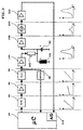
- FIG. 3 shows a block diagram of a device for determining the moisture of the grain.
- the task of the matching amplifier 94 is to adjust the height of the output voltage of the digital-to-analog converter 92 in such a way that it is suitable for controlling a voltage-controlled oscillator (VCO) 96.
- VCO voltage-controlled oscillator
- the output of the voltage controlled oscillator 96 is connected to the input of a second amplifier 100 and the input of a frequency counter 98.
- the microcontroller 90 acts on the digital-to-analog converter 92 with a (digital) signal which causes the latter to provide a stair-step voltage to its output.
- the time-dependent voltage curve at the output of the digital-to-analog converter 92 is below the digital-to-analog converter in FIG 92 reproduced.
- the matching amplifier 94 delivers an output voltage shown below him in Figure 3 with flatter course covering a frequency range of voltage controlled oscillator 96 causes the Resonance range of the resonant circuit 106 in which the Measuring capacitor 52 is located, covers sufficiently.
- a sinusoidal AC voltage is available, its frequency with time sawtooth-shaped rises. This so-called wobble signal is shown in FIG 3 reproduced under the voltage controlled oscillator 96.
- the frequency counter 98 in turn supplies the microcontroller 90 a digital signal that provides information about each Contains frequency. It would be conceivable to have a nominal value of Frequency based on the digital-to-analog converter from the microcontroller 90 92 supplied signal to detect what is due to the Temperature dependency of the voltage-frequency characteristic of the voltage controlled oscillator 96, however, is relatively inaccurate would. By detecting the respective frequency using the Frequency counter 98 leads the microcontroller 90 one more precise, temperature-independent value for the frequency.
- the amplifier 100 which is usually a voltage follower, amplifies the output signal of the voltage-controlled oscillator 96 and feeds the amplified signal to a more or less high-resistance resistor 102, instead of which a capacitor with a low capacitance could also be used.
- the amplifier 100 and the resistor 102 implement a voltage divider in cooperation with a resonance circuit 106 constructed from an inductor 104 and the capacitor 52. The most "The signal present at the end of the resonant circuit 106 depends on the impedance of the resonant circuit 106.
- the resistor 102 If the value of the resistor 102 is sufficiently high, it realizes a current source whose output current is constant, ie is independent of the frequency and impedance of the resonant circuit 106 The magnitude of the voltage at the resonant circuit 106 is then directly proportional to its impedance.
- the connection of the resistor 102 facing away from the amplifier 100 is connected to the parallel resonance circuit 106.
- Its capacitor 52 consists of the metal plates 78, 80, 82, of which the third metal plate 82 is connected to the resistor 102, and the first two metal plates 78, 80 are at ground potential (or vice versa).
- the resonance frequency is 1 / 2 ⁇ (LC) 1/2 . Because of the linear dependence of the frequency on time (see curve under the voltage-controlled oscillator 96), the amplitude could also be dependent on the frequency instead of depending on the frequency Time can be applied without the curve shape would change.
- the gain of amplifier 100 can be in Embodiments of the invention by microcontroller 90 be controllable. This measure allows the resonant circuit 106 supplied voltage amplitude in cases where a strong attenuation by parasitic resistances caused by Surface moisture of the goods are conditional to increase, a sufficiently large signal at the amplifier for evaluation 108 received.
- the voltage applied to the resonant circuit 106 is determined by means of a third amplifier 108 (usually also a Voltage follower) amplified, fed to a rectifier 110, which rectifies them, and by means of a fourth amplifier 112, which is preferably also a voltage follower, again reinforced.
- a third amplifier 108 usually also a Voltage follower
- a rectifier 110 which rectifies them
- a fourth amplifier 112 which is preferably also a voltage follower, again reinforced.
- This Voltage is amplified by the fourth amplifier 112, whose output signal is shown below him in Figure 4, and finally the input of one into the microcontroller 90 integrated analog-digital converter 114 supplied.
- the microcontroller 90 is controlled by software that is stored in a RAM or ROM.
- a measurement of the Moisture from the harvested grain can be continuous or up input from the operator of the combine.
- the Moisture measurement causes microcontroller 90 to Frequency range around the resonance frequency of the resonance circuit 106 run around and based on the output value of the analog-digital converter 114 the resonance frequency is determined. Since the Capacitance of the capacitor 52 over the dielectric constant ⁇ depends on the moisture of the grain, and again the Resonance frequency of the resonant circuit 106 from the capacitance depends in this way is a simple but precise Measurement of the moisture of the grain possible. Under use a table or other stored mathematical Relationships are based on the measured resonance frequency Moisture determined. The determined moisture values can using the position signals of the GPS receiver 50 georeferenced saved or otherwise used become.
- FIG. 4 shows a modified circuit of the voltage divider of Figure 3, in which for the resonant circuit 106 only the pair of metal plates 80, 82 is used.
- the inductance 104 is connected in parallel to this pair of plates 80, 82 and the tension on it is detected, d. H. amplifier 108 fed.
- At the output of amplifier 100 is a second one Inductor 105, the size of which corresponds to that of inductor 104 matches, connected.
- the second connection of the Inductance 105 is with the remaining metal plate 78 connected.
- the result is a voltage divider a series resonance circuit (second inductance 105 and pair of metal plates 78, 82) and a parallel resonant circuit (Resonance circuit 106 with inductance 104 and pair of metal plates 80, 82), whereby on the central metal plate 82 frequency-dependent signal is detected.
- This Voltage divider circuit has a greater slope than the one shown in FIG. 3 thus allows a better one Detection of the resonance frequency. Of course they can Connections of the metal plates 78, 80 are interchanged.
Landscapes
- Chemical & Material Sciences (AREA)
- Life Sciences & Earth Sciences (AREA)
- Health & Medical Sciences (AREA)
- Chemical Kinetics & Catalysis (AREA)
- Electrochemistry (AREA)
- Physics & Mathematics (AREA)
- Environmental Sciences (AREA)
- Analytical Chemistry (AREA)
- Biochemistry (AREA)
- General Health & Medical Sciences (AREA)
- General Physics & Mathematics (AREA)
- Immunology (AREA)
- Pathology (AREA)
- Investigating Or Analyzing Materials By The Use Of Electric Means (AREA)
Applications Claiming Priority (2)
| Application Number | Priority Date | Filing Date | Title |
|---|---|---|---|
| DE19934881 | 1999-07-24 | ||
| DE19934881A DE19934881A1 (de) | 1999-07-24 | 1999-07-24 | Einrichtung zur Messung der Feuchtigkeit von Erntegut |
Publications (2)
| Publication Number | Publication Date |
|---|---|
| EP1072885A2 true EP1072885A2 (fr) | 2001-01-31 |
| EP1072885A3 EP1072885A3 (fr) | 2001-12-12 |
Family
ID=7915997
Family Applications (1)
| Application Number | Title | Priority Date | Filing Date |
|---|---|---|---|
| EP00113310A Withdrawn EP1072885A3 (fr) | 1999-07-24 | 2000-06-23 | Appareil pour la mesure de l'humidité de céréales |
Country Status (4)
| Country | Link |
|---|---|
| US (1) | US6437582B1 (fr) |
| EP (1) | EP1072885A3 (fr) |
| CA (1) | CA2314200C (fr) |
| DE (1) | DE19934881A1 (fr) |
Cited By (3)
| Publication number | Priority date | Publication date | Assignee | Title |
|---|---|---|---|---|
| EP1305994A1 (fr) * | 2001-10-25 | 2003-05-02 | Deere & Company | Capteur d'humidité de grain |
| EP2057883B2 (fr) † | 2007-11-09 | 2017-02-22 | CLAAS Selbstfahrende Erntemaschinen GmbH | Machine de travail agricole |
| RU189493U1 (ru) * | 2018-12-18 | 2019-05-24 | Федеральное государственное бюджетное учреждение науки Удмуртский федеральный исследовательский центр Уральского отделения Российской академии наук | Устройство для измерения влагоудерживающей способности мяса свиней |
Families Citing this family (25)
| Publication number | Priority date | Publication date | Assignee | Title |
|---|---|---|---|---|
| EP1238579B1 (fr) | 2001-03-08 | 2006-04-05 | Deere & Company | Moyens pour mesurer la largeur de coupe de récolte |
| WO2002099765A1 (fr) * | 2001-06-01 | 2002-12-12 | Joergensen Poul Richter | Circuit de resonance |
| US20050189953A1 (en) * | 2002-12-02 | 2005-09-01 | Harvest Tec< Inc. | Method for measuring the moisture of silage as it is harvested |
| CA2430204C (fr) * | 2003-05-28 | 2005-01-04 | William D. Fraser | Humidimetre pour grains |
| DE10350224B4 (de) | 2003-10-27 | 2007-07-26 | Sartorius Ag | Verfahren zur Bestimmung von Feuchte und Dichte eines dielelektrischen Materials |
| DE102004025613B4 (de) * | 2004-05-25 | 2008-08-07 | Erbe Elektromedizin Gmbh | Verfahren und Messvorrichtung zur Bestimmung der Übergangsimpendanz zwischen zwei Teilelektroden einer geteilten Neutralelektrode |
| US7609074B2 (en) * | 2005-02-24 | 2009-10-27 | Sunsweet Growers, Inc. | Electronic moisture tester |
| DE102005059127A1 (de) | 2005-12-10 | 2007-06-28 | Deere & Company, Moline | Ballenpresse mit einer Feuchtemesseinrichtung |
| US7474105B2 (en) * | 2005-12-16 | 2009-01-06 | Colorado Vnet, Llc | Soil moisture sensor systems and methods |
| DE102006034931A1 (de) * | 2006-07-28 | 2008-01-31 | E + E Elektronik Ges.M.B.H. | Schaltungsanordnung und Verfahren zur Feuchtmessung |
| US7743699B1 (en) | 2009-04-09 | 2010-06-29 | Lextron, Inc. | System for automated application of inoculants onto forage materials |
| US7900557B2 (en) * | 2009-04-09 | 2011-03-08 | Lextron, Inc. | System and method for automated application of inoculants onto forage materials |
| US8614586B1 (en) * | 2011-01-12 | 2013-12-24 | The United States Of America As Represented By The Secretary Of Agriculture | Method and apparatus for measuring peanut moisture content |
| GB2496136A (en) * | 2011-11-01 | 2013-05-08 | Isis Innovation | Passive capacitive moisture detector |
| US9668420B2 (en) | 2013-02-20 | 2017-06-06 | Deere & Company | Crop sensing display |
| US9693503B2 (en) | 2013-02-20 | 2017-07-04 | Deere & Company | Crop sensing |
| BE1022144B1 (nl) | 2014-02-17 | 2016-02-19 | Cnh Industrial Belgium Nv | Vochtigheidssensor voor een veldhakselaar |
| US9578808B2 (en) | 2014-05-16 | 2017-02-28 | Deere & Company | Multi-sensor crop yield determination |
| US10034423B2 (en) | 2014-07-29 | 2018-07-31 | Deere & Company | Biomass sensing |
| US9696272B2 (en) * | 2015-08-07 | 2017-07-04 | Silicon Laboratories Inc. | Systems and methods for humidity measurement using dielectric material-based relative humidity sensors |
| US11506630B2 (en) * | 2017-12-28 | 2022-11-22 | Texas Instruments Incorporated | Inductive humidity sensor and method |
| DE102020113658A1 (de) * | 2020-05-20 | 2021-11-25 | Claas Selbstfahrende Erntemaschinen Gmbh | Sensorsystem zur Erfassung von Elementen eines Erntegutstromes |
| DE102020113667A1 (de) * | 2020-05-20 | 2021-11-25 | Claas Selbstfahrende Erntemaschinen Gmbh | Mähdrescher mit einem Sensorsystem |
| WO2022182666A1 (fr) * | 2021-02-23 | 2022-09-01 | Purdue Research Foundation | Humidimètre de grain interconnecté à des téléphones intelligents |
| EP4140285B1 (fr) * | 2021-08-26 | 2026-01-28 | CLAAS Selbstfahrende Erntemaschinen GmbH | Mesure capacitive des paramètres dans une ramasseuse-hacheuse-chargeuse automotrice |
Family Cites Families (16)
| Publication number | Priority date | Publication date | Assignee | Title |
|---|---|---|---|---|
| US1822604A (en) * | 1929-08-22 | 1931-09-08 | Skinner & Sherman Inc | Measuring the freeness of pulp |
| GB396098A (en) * | 1932-01-29 | 1933-07-31 | Charles Herbert William Long | Apparatus for determining the moisture content of flour, corn, beet pulp, tobacco and other moisture containing substances |
| DE1300316B (de) | 1966-01-03 | 1969-07-31 | Trischberger Karl | Vorrichtung zur kontinuierlichen Feuchtemessung von Schuettgut |
| US3693079A (en) * | 1970-04-14 | 1972-09-19 | Charles W E Walker | Apparatus for measuring percent moisture content of particulate material using microwaves and penetrating radiation |
| DE2928487A1 (de) * | 1979-07-14 | 1981-02-05 | Philips Patentverwaltung | Verfahren zur messung der relativen feuchte eines messgutes mit hilfe von mikrowellen im ghz-bereich |
| US4484133A (en) * | 1981-12-23 | 1984-11-20 | Sentrol Systems Ltd. | Microwave moisture sensor |
| US4580233A (en) * | 1982-09-22 | 1986-04-01 | Weyerhaeuser Company | Method of measuring moisture content of dielectric materials |
| US4584522A (en) | 1983-08-11 | 1986-04-22 | Electrex, Inc. | Digital direct reading grain moisture tester |
| DE3743216C2 (de) * | 1987-12-19 | 1996-12-19 | Hauni Werke Koerber & Co Kg | Hochfrequenzschwingkreis |
| US4896795A (en) * | 1988-01-15 | 1990-01-30 | Ediger Randall J | Grain moisture sensor |
| FR2643985B1 (fr) * | 1989-03-03 | 1991-06-28 | Serdia | Appareil de mesure en continu des teneurs en substances d'un produit granuleux, pulverulent ou visqueux |
| US5218309A (en) | 1990-06-25 | 1993-06-08 | The United States Of America As Represented By The Secretary Of Agriculture | Single kernel, seed, nut, or fruit dielectric moisture content measurement |
| US5397994A (en) * | 1993-12-28 | 1995-03-14 | Alkon Corporation | Moisture measurement gauge for particulates including a transmission line forming part of a resonant circuit |
| CA2182989C (fr) * | 1995-09-01 | 2001-03-27 | Frederick William Nelson | Detecteur d'humidite pour le grain |
| US5716272A (en) * | 1996-11-05 | 1998-02-10 | New Holland North America, Inc. | Moisture/yield monitor grain simulator |
| US5859536A (en) * | 1997-01-08 | 1999-01-12 | Oliver Haugen | Moisture sensor having low sensitivity to conductance changes |
-
1999
- 1999-07-24 DE DE19934881A patent/DE19934881A1/de not_active Withdrawn
-
2000
- 2000-06-23 EP EP00113310A patent/EP1072885A3/fr not_active Withdrawn
- 2000-07-18 US US09/618,847 patent/US6437582B1/en not_active Expired - Fee Related
- 2000-07-21 CA CA002314200A patent/CA2314200C/fr not_active Expired - Fee Related
Cited By (6)
| Publication number | Priority date | Publication date | Assignee | Title |
|---|---|---|---|---|
| EP1305994A1 (fr) * | 2001-10-25 | 2003-05-02 | Deere & Company | Capteur d'humidité de grain |
| US6686749B2 (en) | 2001-10-25 | 2004-02-03 | Deere & Company | Multiple frequency grain moisture sensor for combines |
| US6917206B2 (en) | 2001-10-25 | 2005-07-12 | Deere And Company | Multiple frequency grain moisture sensor for combines |
| US6982562B2 (en) | 2001-10-25 | 2006-01-03 | Deere & Company | Multiple frequency grain moisture sensor for combines |
| EP2057883B2 (fr) † | 2007-11-09 | 2017-02-22 | CLAAS Selbstfahrende Erntemaschinen GmbH | Machine de travail agricole |
| RU189493U1 (ru) * | 2018-12-18 | 2019-05-24 | Федеральное государственное бюджетное учреждение науки Удмуртский федеральный исследовательский центр Уральского отделения Российской академии наук | Устройство для измерения влагоудерживающей способности мяса свиней |
Also Published As
| Publication number | Publication date |
|---|---|
| US6437582B1 (en) | 2002-08-20 |
| CA2314200A1 (fr) | 2001-01-24 |
| CA2314200C (fr) | 2004-05-25 |
| DE19934881A1 (de) | 2001-01-25 |
| EP1072885A3 (fr) | 2001-12-12 |
Similar Documents
| Publication | Publication Date | Title |
|---|---|---|
| EP1072885A2 (fr) | Appareil pour la mesure de l'humidité de céréales | |
| EP0655887B1 (fr) | Dispositif de mesure du debit massique | |
| EP0501099B1 (fr) | Dispositif pour mesurer le débit massique avec un condensateur de mesure | |
| EP1305994B1 (fr) | Capteur d'humidité de grain | |
| DE4227922A1 (de) | Vorrichtung zur Messung eines Massestromes | |
| DE19648126B4 (de) | Selbstfahrender Feldhäcksler | |
| EP1704767B1 (fr) | Méthode pour la sélection d'une valeur de préférence | |
| EP2344849B1 (fr) | Dispositif pour la détermination et/ou le contrôle d'une grandeur de processus d'un fluide | |
| EP2944178B1 (fr) | Système de mesure destiné à déterminer le niveau de remplissage | |
| DE10256064B4 (de) | Verfahren und Vorrichtung zur Bestimmung des Wassergehalts und der Leitfähigkeit in Böden und Schüttgütern | |
| EP1321023A1 (fr) | Procédé de determination des pertes dans des machines agricoles | |
| EP0261099B1 (fr) | Instrument de mesure de niveau de liquides non électroconducteurs | |
| EP4140285B1 (fr) | Mesure capacitive des paramètres dans une ramasseuse-hacheuse-chargeuse automotrice | |
| DE3884602T2 (de) | Körnerverlustmonitoren für Mähmaschinen. | |
| EP3912451B1 (fr) | Système de capteur permettant de détecter les éléments d'un flux de produits récoltés | |
| EP4014712A1 (fr) | Procédé de prélèvement d'un échantillon de laboratoire de récolte dans une moissonneuse-batteuse | |
| EP4014711B1 (fr) | Procédé de combinaison des données de mesure at-line et des données de mesure nir on-line destiné à l'analyse du produit de la récolte | |
| EP0924354B1 (fr) | Dispositif de contrôle pour une chasse d'eau d'urinoir | |
| WO2001061286A2 (fr) | Dispositif permettant de determiner le niveau de remplissage d'un agent dans un contenant | |
| EP1164380A2 (fr) | Circuit pout détecter des changements de capacitance | |
| EP4140284A1 (fr) | Système de détection capacitive pour la mesure de l'humidité, de la densité et du débit | |
| DE2205596A1 (de) | Gerät zur Bestimmung eines physikalischen Parameters, insbesondere Feuchtigkeitsprüfgerät für Körner | |
| EP3913807B1 (fr) | Moissonneuse-batteuse dotée d'un système de capteur | |
| DE102021122459A1 (de) | Kapazitive Parametermessung in einem selbstfahrenden Feldhäcksler | |
| DE102024110672A1 (de) | Maschinensteuerungssystem und verfahren zur analyse von landwirtschaftlichem material |
Legal Events
| Date | Code | Title | Description |
|---|---|---|---|
| PUAI | Public reference made under article 153(3) epc to a published international application that has entered the european phase |
Free format text: ORIGINAL CODE: 0009012 |
|
| AK | Designated contracting states |
Kind code of ref document: A2 Designated state(s): AT BE CH CY DE DK ES FI FR GB GR IE IT LI LU MC NL PT SE Kind code of ref document: A2 Designated state(s): BE DE DK FI FR IT |
|
| AX | Request for extension of the european patent |
Free format text: AL;LT;LV;MK;RO;SI |
|
| PUAL | Search report despatched |
Free format text: ORIGINAL CODE: 0009013 |
|
| AK | Designated contracting states |
Kind code of ref document: A3 Designated state(s): AT BE CH CY DE DK ES FI FR GB GR IE IT LI LU MC NL PT SE |
|
| AX | Request for extension of the european patent |
Free format text: AL;LT;LV;MK;RO;SI |
|
| 17P | Request for examination filed |
Effective date: 20020612 |
|
| AKX | Designation fees paid |
Free format text: BE DE DK FI FR IT |
|
| 17Q | First examination report despatched |
Effective date: 20041022 |
|
| STAA | Information on the status of an ep patent application or granted ep patent |
Free format text: STATUS: THE APPLICATION IS DEEMED TO BE WITHDRAWN |
|
| 18D | Application deemed to be withdrawn |
Effective date: 20051119 |