EP1072914A2 - Anpasswerkzeug für Glasfaserstecker zur Exzentrizitätsoptimierung - Google Patents
Anpasswerkzeug für Glasfaserstecker zur Exzentrizitätsoptimierung Download PDFInfo
- Publication number
- EP1072914A2 EP1072914A2 EP00306036A EP00306036A EP1072914A2 EP 1072914 A2 EP1072914 A2 EP 1072914A2 EP 00306036 A EP00306036 A EP 00306036A EP 00306036 A EP00306036 A EP 00306036A EP 1072914 A2 EP1072914 A2 EP 1072914A2
- Authority
- EP
- European Patent Office
- Prior art keywords
- connector
- tuning
- ferrule
- tool
- wall
- Prior art date
- Legal status (The legal status is an assumption and is not a legal conclusion. Google has not performed a legal analysis and makes no representation as to the accuracy of the status listed.)
- Withdrawn
Links
Images


Classifications
-
- G—PHYSICS
- G02—OPTICS
- G02B—OPTICAL ELEMENTS, SYSTEMS OR APPARATUS
- G02B6/00—Light guides; Structural details of arrangements comprising light guides and other optical elements, e.g. couplings
- G02B6/24—Coupling light guides
- G02B6/36—Mechanical coupling means
- G02B6/38—Mechanical coupling means having fibre to fibre mating means
- G02B6/3807—Dismountable connectors, i.e. comprising plugs
- G02B6/3833—Details of mounting fibres in ferrules; Assembly methods; Manufacture
- G02B6/3834—Means for centering or aligning the light guide within the ferrule
- G02B6/3843—Means for centering or aligning the light guide within the ferrule with auxiliary facilities for movably aligning or adjusting the fibre within its ferrule, e.g. measuring position or eccentricity
-
- G—PHYSICS
- G02—OPTICS
- G02B—OPTICAL ELEMENTS, SYSTEMS OR APPARATUS
- G02B6/00—Light guides; Structural details of arrangements comprising light guides and other optical elements, e.g. couplings
- G02B6/24—Coupling light guides
- G02B6/36—Mechanical coupling means
- G02B6/38—Mechanical coupling means having fibre to fibre mating means
- G02B6/3807—Dismountable connectors, i.e. comprising plugs
- G02B6/381—Dismountable connectors, i.e. comprising plugs of the ferrule type, e.g. fibre ends embedded in ferrules, connecting a pair of fibres
- G02B6/3826—Dismountable connectors, i.e. comprising plugs of the ferrule type, e.g. fibre ends embedded in ferrules, connecting a pair of fibres characterised by form or shape
- G02B6/3831—Dismountable connectors, i.e. comprising plugs of the ferrule type, e.g. fibre ends embedded in ferrules, connecting a pair of fibres characterised by form or shape comprising a keying element on the plug or adapter, e.g. to forbid wrong connection
-
- G—PHYSICS
- G02—OPTICS
- G02B—OPTICAL ELEMENTS, SYSTEMS OR APPARATUS
- G02B6/00—Light guides; Structural details of arrangements comprising light guides and other optical elements, e.g. couplings
- G02B6/24—Coupling light guides
- G02B6/26—Optical coupling means
- G02B6/264—Optical coupling means with optical elements between opposed fibre ends which perform a function other than beam splitting
- G02B6/266—Optical coupling means with optical elements between opposed fibre ends which perform a function other than beam splitting the optical element being an attenuator
-
- G—PHYSICS
- G02—OPTICS
- G02B—OPTICAL ELEMENTS, SYSTEMS OR APPARATUS
- G02B6/00—Light guides; Structural details of arrangements comprising light guides and other optical elements, e.g. couplings
- G02B6/24—Coupling light guides
- G02B6/36—Mechanical coupling means
- G02B6/38—Mechanical coupling means having fibre to fibre mating means
- G02B6/3807—Dismountable connectors, i.e. comprising plugs
- G02B6/381—Dismountable connectors, i.e. comprising plugs of the ferrule type, e.g. fibre ends embedded in ferrules, connecting a pair of fibres
- G02B6/3818—Dismountable connectors, i.e. comprising plugs of the ferrule type, e.g. fibre ends embedded in ferrules, connecting a pair of fibres of a low-reflection-loss type
- G02B6/3821—Dismountable connectors, i.e. comprising plugs of the ferrule type, e.g. fibre ends embedded in ferrules, connecting a pair of fibres of a low-reflection-loss type with axial spring biasing or loading means
-
- G—PHYSICS
- G02—OPTICS
- G02B—OPTICAL ELEMENTS, SYSTEMS OR APPARATUS
- G02B6/00—Light guides; Structural details of arrangements comprising light guides and other optical elements, e.g. couplings
- G02B6/24—Coupling light guides
- G02B6/36—Mechanical coupling means
- G02B6/38—Mechanical coupling means having fibre to fibre mating means
- G02B6/3807—Dismountable connectors, i.e. comprising plugs
- G02B6/3833—Details of mounting fibres in ferrules; Assembly methods; Manufacture
- G02B6/3847—Details of mounting fibres in ferrules; Assembly methods; Manufacture with means preventing fibre end damage, e.g. recessed fibre surfaces
- G02B6/3849—Details of mounting fibres in ferrules; Assembly methods; Manufacture with means preventing fibre end damage, e.g. recessed fibre surfaces using mechanical protective elements, e.g. caps, hoods, sealing membranes
-
- G—PHYSICS
- G02—OPTICS
- G02B—OPTICAL ELEMENTS, SYSTEMS OR APPARATUS
- G02B6/00—Light guides; Structural details of arrangements comprising light guides and other optical elements, e.g. couplings
- G02B6/24—Coupling light guides
- G02B6/36—Mechanical coupling means
- G02B6/38—Mechanical coupling means having fibre to fibre mating means
- G02B6/3807—Dismountable connectors, i.e. comprising plugs
- G02B6/3833—Details of mounting fibres in ferrules; Assembly methods; Manufacture
- G02B6/3851—Ferrules having keying or coding means
-
- G—PHYSICS
- G02—OPTICS
- G02B—OPTICAL ELEMENTS, SYSTEMS OR APPARATUS
- G02B6/00—Light guides; Structural details of arrangements comprising light guides and other optical elements, e.g. couplings
- G02B6/24—Coupling light guides
- G02B6/36—Mechanical coupling means
- G02B6/38—Mechanical coupling means having fibre to fibre mating means
- G02B6/3807—Dismountable connectors, i.e. comprising plugs
- G02B6/389—Dismountable connectors, i.e. comprising plugs characterised by the method of fastening connecting plugs and sockets, e.g. screw- or nut-lock, snap-in, bayonet type
- G02B6/3893—Push-pull type, e.g. snap-in, push-on
-
- G—PHYSICS
- G02—OPTICS
- G02B—OPTICAL ELEMENTS, SYSTEMS OR APPARATUS
- G02B6/00—Light guides; Structural details of arrangements comprising light guides and other optical elements, e.g. couplings
- G02B6/24—Coupling light guides
- G02B6/36—Mechanical coupling means
- G02B6/38—Mechanical coupling means having fibre to fibre mating means
- G02B6/3807—Dismountable connectors, i.e. comprising plugs
- G02B6/3898—Tools, e.g. handheld; Tuning wrenches; Jigs used with connectors, e.g. for extracting, removing or inserting in a panel, for engaging or coupling connectors, for assembling or disassembling components within the connector, for applying clips to hold two connectors together or for crimping
Definitions
- This invention relates to an optical fiber connector indexable tuning tool and, more particularly to a tool for testing an calibrating tunable optical fiber connector and apparatus for tuning it.
- connectors for joining fiber segments at their ends, or for connecting optical fiber cables to active or passive devices are an essential component of virtually any optical fiber system.
- the connector or connectors, in joining fiber ends for example, has, as its primary function, the maintenance of the ends in a butting relationship such that the core of one of the fibers is axially aligned with the core of the other fiber so as to maximize light transmissions from one fiber to the other. Another goal is to minimize back reflections.
- Such alignment is extremely difficult to achieve, which is understandable when it is recognized that the mode field diameter of, for example, a single mode fiber is approximately nine (9) microns (0.009 mm).
- Good alignment (low insertion loss) of the fiber ends is a function of the alignment, the width of the gap (if any) between the fiber ends, and the surface condition of the fiber ends, all of which, in turn, are inherent in the particular connector design.
- the connector must also provide stability and junction protection and thus it must minimize thermal and mechanical movement effects.
- Alignment variations between a pair of connectors are the result of the offset of the fiber core centerline from the ferrule centerline.
- This offset which generally varies from connector to connector, is known as "eccentricity", and is defined as the distance between the longitudinal centroidal axis of the ferrule at the end face thereof and the centroidal axis of the optical fiber core held within the ferrule passage and is made up of three vectors. It is often the case, generally, that the ferrule passage is not concentric with the outer cylindrical surface of the ferrule (vector I), which is the reference surface.
- the optical fiber may not be centered within the ferrule passage (vector II whose magnitude is the diametrical difference divided by two) and, also, the fiber core may not be concentric with the outer surface of the fiber (vector III).
- eccentricity can be the result of any one or all of the foregoing.
- the resultant eccentricity vector has two components, magnitude and direction. Where two connectors are interconnected, rotation of one of them will, where eccentricity is present, change the relative position of the fibers, with a consequent increase or decrease in the insertion loss of the connections. Where the magnitude of the eccentricities are approximately equal the direction component is governing, and relative rotation of the connectors until alignment is achieved will produce maximum coupling.
- An optical fiber connector that can be tuned for optimum performance after the connector has been assembled would greatly decrease production costs and further, impart a greater measure of reliability to the connectors. Such a connector would be of significant commercial value.
- the present invention is a tuning index tool for use in tuning tunable optical fiber connections for achieving maximum possible signal transmissivity or minimum insertion loss despite the connector being fully assembled.
- the principles thereof are illustrated with a connector of the LC type for single mode fibers. It is to be understood that the principles of the invention are applicable to numerous other types of connectors such as, for example, the SC, FC and ST type connectors, as well as to other fiber optic type devices.
- the basic components a connector for which the present invention can be used comprise a ferrule-barrel assembly for holding the end of an optical fiber extending axially therethrough and a plug housing member which contains the barrel-ferrule assembly.
- a coil spring member contained within the housing surrounds the barrel and bears against an interior wall of the housing and an enlarged barrel member, thereby supplying forward bias to the barrel-ferrule assembly relative to the housing.
- the barrel member referred to as a flange in the Anderson et al. patent, is shaped to be supported within an interior cavity within the housing in any one of four rotational orientations with respect to the central axis of the fiber holding structure.
- a ferrule extends axially from the enlarged barrel member and contains a fiber end therein.
- the direction of eccentricity of the fiber relative to the central axis can have any one of four rotational or angular orientations.
- the connector is "tuned” to the extent that four orientations are possible.
- the "tuning” is a manufacturing step preceding final assembly of the connector, after which it is no longer “tunable”.
- the ferrule-barrel assembly of the connector is modified so that the enlarged barrel member or flange is optimally hexagonal in shape, and has a tapered or chamfered leading surface which may be slotted.
- the housing is also modified so that the interior cavity is hexagonal in shape to accommodate the barrel member in any of six rotational orientations and a sloped constriction against which the leading surface bears in its forward position. Tuning of the fully assembled connector is accomplished by the application of an axial force to the barrel member, as by a spanner wrench fitted within the slots in the leading surface, sufficient to overcome the bias of the coil spring and to push the barrel portion rearwardly out of engagement with the hexagonally shaped recess in the housing and the sloped constriction.
- the ferrule-barrel assembly is then incrementably rotatable to any of six angular orientations, sixty degrees (60°) apart. It should be noted that a lesser number of surfaces can be used if the diagonal distance of the barrel cross-section is reduced sufficiently to allow rotation thereof within the plug housing or, alternatively if the housing bore is enlarged, which, however, weakens the walls of the housing. Fewer surfaces means larger increments of rotation and hence less precise reduction in loss. Also, more than six surfaces may be used, however, the improvement over six surfaces is slight and the clearance surrounding the barrel makes limiting rotation within the housing difficult to achieve.
- an indexable tuning tool having a spring loaded split LC adapter that is keyed and labeled to measure the optical performance of an LC connector at six different angular orientations.
- the tool has a longitudinal split ceramic sleeve therein for aligning two LC connector end faces.
- a test jumper cable having an LC connector which has an eccentricity of a magnitude greater than that of the connector to be tuned and a known direction (angular orientation) is inserted into the sleeve and the production jumper connector is fitted into the sleeve so that the connector ferrule ends abut.
- the opposite end of the jumper cable is connected to an optical source, or an optical detector, and the production jumper is connected to a source or detector to complete a test circuit.
- the test jumper has an eccentricity of 1.8 to 3.5 ⁇ m relative to the ferrule axis, and has an angular orientation of zero degrees (0°) or one hundred eighty degrees (180°), preferably the former which is an upright vertical orientation. Insertion loss measurements are then taken and the initial loss is noted.
- the portion of the tool holding the product jumper is spring loaded to allow separation of the fiber end faces and rotation thereof. The tool is thus rotated in sixty degree (60°) increments, with measured insertion loss being recorded at each increment. The angular orientation of the product jumper that yields minimum insertion loss is thus determined.
- the labeling on the tool indicates how many degrees, in sixty degree increments, the product jumper had to be rotated to produce minimum insertion loss.
- the angular orientation of the connector of the test jumper is known, preferably, as stated hereinbefore, zero degrees (0°) or straight up or vertical
- the tool indicates how many incremental stages the product jumper requires to have a corresponding vertical orientation. It is also feasible to ascertain, instead of minimum insertion loss, the angular orientation for maximum insertion loss. Rotation of 180° from this orientation yields the orientation for minimum insertion loss. In both methods, one or the other of the extremes of insertion loss is determined.
- a tool, used for tuning, in the form of a spanner wrench is included as an element of the tuning test operation.
- the tuning tool wrench comprises an enlarged handle shaped, such as hexagonally, for gripping from which extends a hollow sleeve having a distal end with first and second tangs extending therefrom.
- the sleeve is adapted and sized to fit over the ferrule of the product jumper connector with the tangs engaging the slots in the leading or front surface of the barrel member.
- the tangs are engaged and the ferrule-barrel assembly is pushed to the rear out of engagement with the plug housing and against the spring bias, so that the ferrule-barrel assembly may be rotated the required number of degrees as indicated by the index tool to the angular orientation yielding minimum insertion loss where the connector is mated with another connector having vertical orientation of its eccentricity.
- the spanner wrench of the invention has a shoulder from which the sleeve extends, which butts against the housing to limit the insertion distance of the wrench. The distance from the face of the shoulder to the tangs is chosen such that the ferrule-barrel assembly, when pushed against the coil spring, does not cause the spring to bottom, which can be damaging to the spring.
- the unique structure of the connector permits tuning of the assembled connector. Further, the tuning tool enables additional rotations of the ferrule-barrel assembly when desired, for whatever reason.
- Fig. 1 is an exploded perspective view of the principal components of an LC type connector 11 which embodies the principles of the present invention. It is to be understood that these principles are also applicable to other types of connectors, such as an ST, SC, or other amenable to modification to incorporate these principles.
- Connector 11 comprises a plug housing formed of a front section 12 and a rear section 13 having an extended portion 14 which fits into section 12 and latches thereto by means of slots 16-16 in front section 12 and latching members 17-17.
- Members 12 and 13 are preferably made of a suitable plastic material.
- Member or front section 12 has a resilient latching arm 18 extending therefrom for latching the connector 11 in place is a receptacle or adapter.
- Member or section 13 has extending therefrom a resilient latch arm or trigger guard 19, the distal end of which, when the two sections 12 and 13 are assembled, overlies the distal end of arm 18 to protect it from snagging and to prevent nearby cables from becoming entangled.
- latch arm 18 and guard 19 are molded with their respective housing sections 12 and 13, respectively, and form 'living hinges" therewith, which enable them to be moved up and down between latching and unlatching positions.
- Front section 12 has a bore 21 extending therethrough which, when the parts are assembled, is coextensive with a bore 22 extending through rear section 13.
- the bores 21 and 22 accommodate a ferrule-barrel assembly 23 which comprises a hollow tubular member 24 having an enlarged flange or barrel member 26 from which extends a ferrule 27 which may be made of a suitably hard material such as, preferably, ceramic, glass, or metal. Ferrule 27 has a bore 28 extending therethrough for receiving and holding an optical fiber therein.
- a coil spring 29 surrounds the tubular portion 24 of the assembly 23, with one end bearing against the rear surface of flange 26 and the other end bearing against an interior shoulder in rear section 13, as will best be seen in subsequent figures.
- the uncoated portion of the optical fiber is inserted into bore 28 of ferrule 27 and adhesively attached thereto.
- Spring 29 is compressed as the sections 12 and 13 are connected and supplies a forward bias against the rear of flange 26 and, hence, to ferrule 27.
- This arrangement of ferrule 27 and spring 29 is considered to be a "floating" design. Prior to connection, the spring 29 causes ferrule 27 to overtravel its ultimate connected position.
- FIG. 2 depicts the assembled connector 11 in its shipping or handling configuration.
- flange 26 has a hexagonally shaped portion 33 and a front tapered portion 34, which can be a tapered extension of the hexagon shape. While the following discussion relates to a multi-faceted ferrule holding member, it is to be understood that the term "faceted" is intended to include other locating arrangements such as, for example, sots or splines.
- Front section 12 has a flange seating opening 36 formed in a transverse wall 37 thereof which has a hexagonally shaped portion 38 and a tapered portion 39 dimensioned to receive and seat flange 26, as best seen in Figs. 3a and 3b. In Fig.
- the opening 36 has, instead of a hexagonal shape, a plurality of splines 40 extending inwardly therefrom, a modification especially adapted to receive the ferrule-barrel assembly of Figs. 4c and 4d. That portion 41 of bore 21 immediately to the rear of portion 38 has a diameter sufficient to allow rotation of flange 26 when it is pushed to the rear and disengaged from the seat 36.
- flange 26 when flange 26 is pushed to the rear (against the force of spring 29) it may be rotated and, when released, re-seated with tapered portion 34 acting as a guide.
- the hexagonal configuration makes it possible to seat the flange 26 in any of six angular rotational positions, each sixty degrees (60°) apart. It has been found that a flange having fewer than six sides cannot be rotated in the assembled connector unless the diameter of bore portion 41 is increased because the diagonal of a four sided flange is too great for rotation of the flange. However, increasing the diameter of portion 41 seriously weakens the walls of the housing section 12. Further, in the tuning of the connector it has been found that six sides gives a more accurate tuning for reduction of insertion loss. The use of a flange with more than six sides is possible, and gives an even greater tuning accuracy by creating smaller increments of rotation.
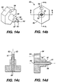
- Figs. 4a and 4b show a modification of a barrel-ferrule assembly 23 in which the sloped or tapered portion 34 has a notch 42 therein for accommodating a tuning tool, not shown.
- Figs. 5a and 5b depict, in cross-section, the connector 11 of the present invention showing, in Fig. 5a, the flange seated position and in Fig. 5b, the disengaged and rotatable position of the flange for tuning, demonstrating how tuning is achievable with a fully assembled connector.
- the thickness of the wall 37 is slightly less than that of flange 26, thereby insuring that flange 26 can be disengaged (pushed back) from the seat 36 to where it can be rotated without causing spring 29 to bottom.
- Connector 11 is shown mounted on the end of a cable 43 containing a fiber 44, which extend through connector 11 as shown.
- Fig. 6 is a graph of the effect of offset between two fiber ends (two connectors) which is "transverse offset" versus attenuation.
- offsets such as 0.5 microns (point Y )
- the loss is corresponding small, about 0.05 dB .
- the loss remains well below 0.3 dB , which is a preferred limit on loss.
- the next increment range of offset, from one micron to two microns (point Y '') shows an exponential increase in loss, from about 0.22 dB to 0.9 dB .
- the loss increases exponentially. It can be appreciated therefore, that tunability of the connector to decrease the offset between the two fiber ends is highly desirable.
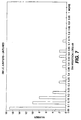
- Fig. 7 is a bar chart of the measurements on a group of untuned connectors showing a wide distribution of insertion loss. It can be seen that several of the connectors exceed the preferred insertion loss limit of 0.3 dB .
- Fig. 8 is a bar chart of the same group of connectors after tuning, showing a compression of the loss distribution to where only one connector exceeds the 0.3 dB limit.
- tuning material ly enhances the performance of connectors where there are eccentricities present, which is virtually always the case.
- Fig. 9 is an exploded perspective view of the tuning index tool 51 of the invention discussed hereinbefore.
- Tool 51 comprises housing comprising a hollow circular member 52 , preferably of a plastic material, having a retaining wall 53 for a warped leaf spring 54.
- Member 52 has a plurality of openings or windows 56 around the periphery thereof, spaced sixty degrees (60°) apart, and a plurality of keyways 57, only one of which is shown in Fig. 9, which are spaced around the inner periphery of member 52 and spaced preferably one hundred twenty degrees (120°) apart.
- Fig. 11 is a cross-section of tool 51 along the lines A-A of Fig.
- member 52 has a wall 58 therein, formed by disc member 59 which has a connector adapter 61 affixed thereto on one side.
- disc 59 Extending from the other side of disc 59 is a split sleeve 62, preferably of a ceramic material, held within adapter 61, for receiving the ferrule of a connector mounted in adapter 61.
- Sleeve 62 also receives the ferrule of a connector mounted in a second adapter 63 which is affixed to a wall 64 of a movable member 66.
- Disc member 59 has a circular array of locating holes 67 surrounding a locating ring 68 which seats in a circular groove 69 wall 64 of member 66. As best seen in Fig.
- wall 64 has extending therefrom six locating projections 71 which are dimensioned to fit within openings or locating holes 67. Holes 67 form a circular array, with the holes spaced sixty degrees (60°) apart, and, importantly, with one of the holes being at zero degrees (0°) relative to the vertical axis of adapter 61. On the other hand, locating projections or pins 71 are in a circular array and spaced sixty degrees (60°) apart, with one projection or pin 71 being at zero degrees (0°) relative to the vertical axis of adapter 63.
- the outer edge of wall 64 preferably has a locating mark 72 thereon which, as will be apparent hereinafter, is visible through the windows 56 as member 66 is rotated during tests.
- locating mark 72 is aligned with the vertical axis of adapter 63 and is, as a consequence, an indicator of the zero degree (0°) location of adapter 63. It should be obvious that six pins 71 are not absolutely necessary, since the locating feature can be accomplished with as few as one pin.
- Tool 51 is assembled by spring 54 being placed within member 52 to bear against retaining wall 53, as seen in Fig. 11. Movable member 66 is then inserted into member 52 so that wall 64 rests against spring 54. Disc member 59, the periphery of which has projecting key 73, is then inserted into member 52 with the key being inserted into keyways 57, and latched therewithin by a plurality of peripherally disposed latching members 74 on member 59 and latching slots 76 within member 52. Sleeve 62 is fitted within the two adapter sleeves, as shown in Fig. 11. The assembled tool 51 is shown in Figs. 10 and 12, and the tool in use is shown in Fig. 13.
- a test jumper 81 which terminates in an LC connector, not shown, is inserted into adapter 63.
- the connector has a known magnitude of offset or eccentricity greater than the connector 82 to be tested for tuning oriented vertically (0°).
- the orientation can be 180°, which is also vertical, but the following discussion will be directed toward the 0° orientation.
- the magnitude of the eccentricity relative to the ferrule axis is 1.8 to 3.5 microns.
- the connector 82 to be tuned is inserted into adapter 61 and has a unknown amplitude and direction of eccentricity.
- marker 72 showing in one of the windows, such as, for example, the 0° orientation window, which may be indicated by a marking strip 83 affixed on the periphery of member 52 (see Fig. 12).
- insertion loss is measured.
- the operator then pulls member 66, which is ridged to give purchase, in the direction indicated by arrow A, against spring 54 until the ferrules of the two connectors are disengaged and locating pins 71 are cleared from openings 67.
- the member 66 is then rotated, for example, clockwise direction B), until the marker 72 appears in the next window 56, in other words, member 66 is rotated 60°, as is connector 63. Insertion loss is again measured and recorded.
- the process is repeated for five more incremental rotations, and the measured insertion losses will have a maximum and a minimum. It is noted at which incremental position the insertion loss was the least, for example, it was least at the second rotational position, which is an indication that 120° of rotation resulted in closest alignment of the fiber ends.
- the connector to be tuned is then removed from the tool. Suitable means, such as the especially designed spanner wrench previously discussed, is then used to rotate the ferrule of the connector 120° counter-clockwise in the manner explained hereinbefore, to "tune" the connector.
- the product connector must then be tuned to the indicated orientation.
- the tuning of the connector is discussed in connection with Figs. 5a and 5b wherein it is shown that the ferrule 27 is pushed into the connector against the force of spring 29 until the flange 26 clears the flange seating opening 36 sufficiently to allow the ferrule/barrel assembly to be rotated.
- This movement of the ferrule may be accomplished by any suitable means, such as, for example, needle nose pliers which are used to grip the ferrule and to push it.
- the ferrule is made of sufficiently hard material, such as a ceramic, that judicious gripping thereof with pliers is generally insufficient to damage the ferrule. It is desirable that the ferrule-barrel assembly not be pushed so far that the spring 29 bottoms, which can, over time, weaken the spring or even damage it.
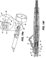
- Figs. 14a through 14f there are shown several views of a unique tuning wrench 83 for use with the ferrule-barrel arrangement of Fig. 4a.
- Wrench 83 has a first, enlarged, body portion 84 having a hexagonal shape for ease of gripping. It is to be understood that portion 84 can have other shapes besides hexagonal; however, the hexagonal shape makes possible an easy determination of when a 60° rotation has been achieved.
- Extending from portion 84 is a limiting member 86 having a diameter greater than bore 21 in the front portion of connector 11 and a flat face 87 at its distal end. Extending from face 87 is a strengthening member 88 which has a diameter that is less than the bore 21.
- a central bore 89 extends through member 84, 86, and 87 as shown.
- a tubular member 91 is located in bore 89 and affixed thereto.
- Member 91 is preferably made of metal, although it is not intended that it be restricted thereto, since other materials may be suitable.
- the distal end of member 91 has first and second tangs 92 and 93, diametrically opposite each other which form a spanner wrench.
- the inner diameter of member 91 is such that it slides easily over the ferrule 27 of the connector 11, and tool 83 may then be pushed forward to where the tangs 92 and 93 engage slot 42 of the flange member 26. It will be obvious to workers in the art that one tang can be used. Fig.
- Body portion 84 preferably has a reference hole 94, located at one of the cusps of the hexagonal shape, and, as seen in Fig. 14b, the plane in which the tangs 92 and 93 lie is normal to the vertical centerline of reference hole 94.
- the wrench 83 is primarily intended for use with the tuning index tool 51 and is used to make the incremental rotations of the product connector, the number of increments being indicated by the results of the test process discussed hereinbefore. However, the wrench may also be used to make tuning adjustments in the field to the fully assembled product connector.
Landscapes
- Physics & Mathematics (AREA)
- General Physics & Mathematics (AREA)
- Optics & Photonics (AREA)
- Mechanical Coupling Of Light Guides (AREA)
Applications Claiming Priority (2)
| Application Number | Priority Date | Filing Date | Title |
|---|---|---|---|
| US363908 | 1999-07-28 | ||
| US09/363,908 US6464402B1 (en) | 1999-07-28 | 1999-07-28 | Optical fiber connector tuning index tool |
Publications (2)
| Publication Number | Publication Date |
|---|---|
| EP1072914A2 true EP1072914A2 (de) | 2001-01-31 |
| EP1072914A3 EP1072914A3 (de) | 2004-03-03 |
Family
ID=23432231
Family Applications (1)
| Application Number | Title | Priority Date | Filing Date |
|---|---|---|---|
| EP00306036A Withdrawn EP1072914A3 (de) | 1999-07-28 | 2000-07-17 | Anpasswerkzeug für Glasfaserstecker zur Exzentrizitätsoptimierung |
Country Status (4)
| Country | Link |
|---|---|
| US (1) | US6464402B1 (de) |
| EP (1) | EP1072914A3 (de) |
| JP (1) | JP3659483B2 (de) |
| CA (1) | CA2314745A1 (de) |
Cited By (16)
| Publication number | Priority date | Publication date | Assignee | Title |
|---|---|---|---|---|
| US6629782B2 (en) | 2002-02-04 | 2003-10-07 | Adc Telecommunications, Inc. | Tuned fiber optic connector and method |
| US6913396B2 (en) | 2002-11-01 | 2005-07-05 | Adc Telecommunications, Inc. | Tunable fiber optic connector and device and method for tuning a connector |
| US6916120B2 (en) | 2002-01-30 | 2005-07-12 | Adc Telecommunications, Inc. | Fiber optic connector and method |
| WO2005069051A1 (en) * | 2003-12-24 | 2005-07-28 | 3M Innovative Properties Company | Optical connector, optical fiber with connector, optical fiber connecting device, and optical fiber connection method |
| EP1655627A3 (de) * | 2004-11-04 | 2006-06-28 | Panduit Corporation | Eine optische LC-Steckverbinderanordnung und ein Werkzeug mit einer Nocke zum Zusammenbau |
| US7201518B2 (en) | 2004-04-14 | 2007-04-10 | Adc Telecommunications, Inc. | Fiber optic connector and method |
| WO2007146355A2 (en) | 2006-06-15 | 2007-12-21 | Tyco Electronics Corporation | Connector for jacketed optical fiber cable |
| EP2012152A1 (de) * | 2007-07-06 | 2009-01-07 | Ridgemount Technologies Limited | Optischer Zwingehalter |
| US7556438B2 (en) | 2004-07-16 | 2009-07-07 | 3M Innovative Properties Company | Optical connector and optical fiber connecting system |
| US7637673B2 (en) | 2004-07-16 | 2009-12-29 | 3M Innovative Properties Company | Optical connector and optical fiber connecting system |
| US9081154B2 (en) | 2012-09-12 | 2015-07-14 | Tyco Electronics Raychem Bvba | Method of tuning a fiber optic connector |
| WO2016095213A1 (en) * | 2014-12-19 | 2016-06-23 | Tyco Electronics (Shanghai) Co., Ltd. | Hardened fiber optic connector with pre-compressed spring |
| US9927581B1 (en) * | 2016-10-28 | 2018-03-27 | Corning Optical Communications LLC | Connector tuning method and ferrule for fiber optic cable assemblies |
| EP3650898A1 (de) * | 2012-02-20 | 2020-05-13 | Commscope Technologies LLC | Faseroptische anordnung |
| US11150412B2 (en) | 2018-01-31 | 2021-10-19 | Commscope Technologies Llc | Tunable fiber optic connectors |
| WO2024145684A1 (en) * | 2022-12-31 | 2024-07-04 | Ppc Broadband, Inc. | Optical fiber connector configured to be tuned so as to minimize signal transmission loss |
Families Citing this family (101)
| Publication number | Priority date | Publication date | Assignee | Title |
|---|---|---|---|---|
| US6760531B1 (en) | 1999-03-01 | 2004-07-06 | Adc Telecommunications, Inc. | Optical fiber distribution frame with outside plant enclosure |
| CN1398232A (zh) * | 2000-02-07 | 2003-02-19 | 特赫鲁赫鲁器材有限公司 | 轻便式滑雪拉索设备 |
| US6663293B2 (en) * | 2001-03-16 | 2003-12-16 | Fitel Usa Corp. | Tunable optical fiber connector |
| US6550979B1 (en) * | 2001-10-19 | 2003-04-22 | Corning Cable Systems Llc | Floating connector subassembly and connector including same |
| US7396165B2 (en) * | 2002-11-01 | 2008-07-08 | Finisar Corporation | Counterbore base member for ferrule-type optical connector |
| US6859604B2 (en) * | 2003-01-30 | 2005-02-22 | Panduit Corp. | Tuning tool for tunable fiber optic connector |
| US7142764B2 (en) | 2003-03-20 | 2006-11-28 | Tyco Electronics Corporation | Optical fiber interconnect cabinets, termination modules and fiber connectivity management for the same |
| AU2003220833A1 (en) * | 2003-04-02 | 2004-11-01 | Suncall Corporation | Optical fiber connector |
| US7198409B2 (en) | 2003-06-30 | 2007-04-03 | Adc Telecommunications, Inc. | Fiber optic connector holder and method |
| US7233731B2 (en) | 2003-07-02 | 2007-06-19 | Adc Telecommunications, Inc. | Telecommunications connection cabinet |
| US6983095B2 (en) * | 2003-11-17 | 2006-01-03 | Fiber Optic Network Solutions Corporation | Systems and methods for managing optical fibers and components within an enclosure in an optical communications network |
| US7369741B2 (en) | 2003-11-17 | 2008-05-06 | Fiber Optics Network Solutions Corp. | Storage adapter with dust cap posts |
| USD528505S1 (en) | 2003-12-03 | 2006-09-19 | Panduit Corp. | Fiber optic connector |
| US7218827B2 (en) | 2004-06-18 | 2007-05-15 | Adc Telecommunications, Inc. | Multi-position fiber optic connector holder and method |
| US7194181B2 (en) | 2005-03-31 | 2007-03-20 | Adc Telecommunications, Inc. | Adapter block including connector storage |
| US7623749B2 (en) | 2005-08-30 | 2009-11-24 | Adc Telecommunications, Inc. | Fiber distribution hub with modular termination blocks |
| US7720343B2 (en) | 2006-02-13 | 2010-05-18 | Adc Telecommunications, Inc. | Fiber distribution hub with swing frame and modular termination panels |
| US7816602B2 (en) | 2006-02-13 | 2010-10-19 | Adc Telecommunications, Inc. | Fiber distribution hub with outside accessible grounding terminals |
| US7760984B2 (en) | 2006-05-04 | 2010-07-20 | Adc Telecommunications, Inc. | Fiber distribution hub with swing frame and wrap-around doors |
| US7466891B2 (en) * | 2006-06-13 | 2008-12-16 | Panduit Corp. | Activation tool for a fiber optic connector |
| US7496268B2 (en) * | 2006-12-13 | 2009-02-24 | Corning Cable Systems Llc | High density fiber optic hardware |
| US7822310B2 (en) | 2007-02-28 | 2010-10-26 | Corning Cable Systems Llc | Fiber optic splice trays |
| US8798427B2 (en) | 2007-09-05 | 2014-08-05 | Corning Cable Systems Llc | Fiber optic terminal assembly |
| US8229265B2 (en) | 2007-11-21 | 2012-07-24 | Adc Telecommunications, Inc. | Fiber distribution hub with multiple configurations |
| US7889961B2 (en) | 2008-03-27 | 2011-02-15 | Corning Cable Systems Llc | Compact, high-density adapter module, housing assembly and frame assembly for optical fiber telecommunications |
| ES2560802T3 (es) | 2008-08-27 | 2016-02-22 | Adc Telecommunications, Inc. | Adaptador de fibra óptica con estructura de alineamiento de casquillos moldeada integralmente |
| US11294136B2 (en) | 2008-08-29 | 2022-04-05 | Corning Optical Communications LLC | High density and bandwidth fiber optic apparatuses and related equipment and methods |
| US8452148B2 (en) | 2008-08-29 | 2013-05-28 | Corning Cable Systems Llc | Independently translatable modules and fiber optic equipment trays in fiber optic equipment |
| EP2344915A4 (de) | 2008-10-09 | 2015-01-21 | Corning Cable Sys Llc | Faseroptischer anschluss mit adaptertafel, die sowohl eingangs- als auch ausgangsfasern von einem optischen teiler unterstützt |
| US8879882B2 (en) | 2008-10-27 | 2014-11-04 | Corning Cable Systems Llc | Variably configurable and modular local convergence point |
| WO2010059623A1 (en) | 2008-11-21 | 2010-05-27 | Adc Telecommunications, Inc. | Fiber optic telecommunications module |
| EP2221932B1 (de) | 2009-02-24 | 2011-11-16 | CCS Technology Inc. | Haltevorrichtung für ein Kabel oder eine Anordnung zur Verwendung mit einem Kabel |
| EP2237091A1 (de) | 2009-03-31 | 2010-10-06 | Corning Cable Systems LLC | Lösbar montierbares LWL-Leitungsendgerät |
| US8699838B2 (en) | 2009-05-14 | 2014-04-15 | Ccs Technology, Inc. | Fiber optic furcation module |
| US8538226B2 (en) | 2009-05-21 | 2013-09-17 | Corning Cable Systems Llc | Fiber optic equipment guides and rails configured with stopping position(s), and related equipment and methods |
| US9075216B2 (en) | 2009-05-21 | 2015-07-07 | Corning Cable Systems Llc | Fiber optic housings configured to accommodate fiber optic modules/cassettes and fiber optic panels, and related components and methods |
| US8712206B2 (en) | 2009-06-19 | 2014-04-29 | Corning Cable Systems Llc | High-density fiber optic modules and module housings and related equipment |
| JP2012530943A (ja) | 2009-06-19 | 2012-12-06 | コーニング ケーブル システムズ リミテッド ライアビリティ カンパニー | 高い光ファイバケーブル実装密度の装置 |
| DE20160489T1 (de) | 2009-06-19 | 2024-06-20 | Corning Optical Communications LLC | Glasfaservorrichtungen mit hoher dichte und bandbreite und zugehörige ausrüstung und verfahren |
| CN101988976B (zh) * | 2009-08-05 | 2012-10-03 | 华为技术有限公司 | 微型双芯光纤连接器 |
| ES2398782T3 (es) * | 2009-09-03 | 2013-03-21 | Tyco Electronics Raychem Bvba | Conjunto conector de fibras ópticas y unidad de terminación de fibras |
| US8467651B2 (en) | 2009-09-30 | 2013-06-18 | Ccs Technology Inc. | Fiber optic terminals configured to dispose a fiber optic connection panel(s) within an optical fiber perimeter and related methods |
| US8625950B2 (en) | 2009-12-18 | 2014-01-07 | Corning Cable Systems Llc | Rotary locking apparatus for fiber optic equipment trays and related methods |
| US8992099B2 (en) | 2010-02-04 | 2015-03-31 | Corning Cable Systems Llc | Optical interface cards, assemblies, and related methods, suited for installation and use in antenna system equipment |
| CN102870021B (zh) | 2010-03-02 | 2015-03-11 | 蒂安电子服务有限责任公司 | 光纤通信模块 |
| US9547144B2 (en) | 2010-03-16 | 2017-01-17 | Corning Optical Communications LLC | Fiber optic distribution network for multiple dwelling units |
| US8913866B2 (en) | 2010-03-26 | 2014-12-16 | Corning Cable Systems Llc | Movable adapter panel |
| WO2011159387A1 (en) | 2010-04-16 | 2011-12-22 | Ccs Technology, Inc. | Sealing and strain relief device for data cables |
| US8792767B2 (en) | 2010-04-16 | 2014-07-29 | Ccs Technology, Inc. | Distribution device |
| EP2381284B1 (de) | 2010-04-23 | 2014-12-31 | CCS Technology Inc. | Glasfaserverteilungsvorrichtung für Unterboden |
| US8879881B2 (en) | 2010-04-30 | 2014-11-04 | Corning Cable Systems Llc | Rotatable routing guide and assembly |
| US9519118B2 (en) | 2010-04-30 | 2016-12-13 | Corning Optical Communications LLC | Removable fiber management sections for fiber optic housings, and related components and methods |
| US9632270B2 (en) | 2010-04-30 | 2017-04-25 | Corning Optical Communications LLC | Fiber optic housings configured for tool-less assembly, and related components and methods |
| US9720195B2 (en) | 2010-04-30 | 2017-08-01 | Corning Optical Communications LLC | Apparatuses and related components and methods for attachment and release of fiber optic housings to and from an equipment rack |
| US8705926B2 (en) | 2010-04-30 | 2014-04-22 | Corning Optical Communications LLC | Fiber optic housings having a removable top, and related components and methods |
| US8660397B2 (en) | 2010-04-30 | 2014-02-25 | Corning Cable Systems Llc | Multi-layer module |
| US9075217B2 (en) | 2010-04-30 | 2015-07-07 | Corning Cable Systems Llc | Apparatuses and related components and methods for expanding capacity of fiber optic housings |
| CN101881865B (zh) * | 2010-06-17 | 2012-03-07 | 深圳日海通讯技术股份有限公司 | 一种光纤连接器 |
| US8718436B2 (en) | 2010-08-30 | 2014-05-06 | Corning Cable Systems Llc | Methods, apparatuses for providing secure fiber optic connections |
| US9720197B2 (en) | 2010-10-19 | 2017-08-01 | Corning Optical Communications LLC | Transition box for multiple dwelling unit fiber optic distribution network |
| US9279951B2 (en) | 2010-10-27 | 2016-03-08 | Corning Cable Systems Llc | Fiber optic module for limited space applications having a partially sealed module sub-assembly |
| US8662760B2 (en) | 2010-10-29 | 2014-03-04 | Corning Cable Systems Llc | Fiber optic connector employing optical fiber guide member |
| US9116324B2 (en) | 2010-10-29 | 2015-08-25 | Corning Cable Systems Llc | Stacked fiber optic modules and fiber optic equipment configured to support stacked fiber optic modules |
| AU2011336747A1 (en) | 2010-11-30 | 2013-06-20 | Corning Cable Systems Llc | Fiber device holder and strain relief device |
| US8753022B2 (en) | 2010-11-30 | 2014-06-17 | Adc Telecommunications, Inc. | LC connector and method of assembly |
| CN103403594B (zh) | 2011-02-02 | 2016-11-23 | 康宁光缆系统有限责任公司 | 适用于为设备机架中的光学底板建立光学连接的稠密的光阀遮蔽的光纤连接器及总成 |
| US9008485B2 (en) | 2011-05-09 | 2015-04-14 | Corning Cable Systems Llc | Attachment mechanisms employed to attach a rear housing section to a fiber optic housing, and related assemblies and methods |
| CN103649805B (zh) | 2011-06-30 | 2017-03-15 | 康宁光电通信有限责任公司 | 使用非u宽度大小的外壳的光纤设备总成以及相关方法 |
| US8953924B2 (en) | 2011-09-02 | 2015-02-10 | Corning Cable Systems Llc | Removable strain relief brackets for securing fiber optic cables and/or optical fibers to fiber optic equipment, and related assemblies and methods |
| US9417418B2 (en) | 2011-09-12 | 2016-08-16 | Commscope Technologies Llc | Flexible lensed optical interconnect device for signal distribution |
| CN108594384B (zh) | 2011-10-07 | 2022-03-08 | Adc电信公司 | 光纤盒、系统和方法 |
| US9038832B2 (en) | 2011-11-30 | 2015-05-26 | Corning Cable Systems Llc | Adapter panel support assembly |
| US9219546B2 (en) | 2011-12-12 | 2015-12-22 | Corning Optical Communications LLC | Extremely high frequency (EHF) distributed antenna systems, and related components and methods |
| CN102520489B (zh) * | 2012-01-11 | 2016-04-13 | 深圳日海通讯技术股份有限公司 | 一种光纤连接器及其装配方法 |
| CN102565963B (zh) * | 2012-02-27 | 2017-04-26 | 深圳日海通讯技术股份有限公司 | 一种高密度光纤连接器及其装配方法 |
| US10110307B2 (en) | 2012-03-02 | 2018-10-23 | Corning Optical Communications LLC | Optical network units (ONUs) for high bandwidth connectivity, and related components and methods |
| US9004778B2 (en) | 2012-06-29 | 2015-04-14 | Corning Cable Systems Llc | Indexable optical fiber connectors and optical fiber connector arrays |
| US9250409B2 (en) | 2012-07-02 | 2016-02-02 | Corning Cable Systems Llc | Fiber-optic-module trays and drawers for fiber-optic equipment |
| US9049500B2 (en) | 2012-08-31 | 2015-06-02 | Corning Cable Systems Llc | Fiber optic terminals, systems, and methods for network service management |
| CN202758106U (zh) * | 2012-09-06 | 2013-02-27 | 深圳日海通讯技术股份有限公司 | 一种改进型光纤接入插头 |
| US9042702B2 (en) | 2012-09-18 | 2015-05-26 | Corning Cable Systems Llc | Platforms and systems for fiber optic cable attachment |
| US9146362B2 (en) | 2012-09-21 | 2015-09-29 | Adc Telecommunications, Inc. | Insertion and removal tool for a fiber optic ferrule alignment sleeve |
| US9146374B2 (en) | 2012-09-28 | 2015-09-29 | Adc Telecommunications, Inc. | Rapid deployment packaging for optical fiber |
| IN2015DN02869A (de) | 2012-09-28 | 2015-09-11 | Tyco Electronics Ltd Uk | |
| US9223094B2 (en) | 2012-10-05 | 2015-12-29 | Tyco Electronics Nederland Bv | Flexible optical circuit, cassettes, and methods |
| US8909019B2 (en) | 2012-10-11 | 2014-12-09 | Ccs Technology, Inc. | System comprising a plurality of distribution devices and distribution device |
| ES2551077T3 (es) | 2012-10-26 | 2015-11-16 | Ccs Technology, Inc. | Unidad de gestión de fibra óptica y dispositivo de distribución de fibra óptica |
| US8985862B2 (en) | 2013-02-28 | 2015-03-24 | Corning Cable Systems Llc | High-density multi-fiber adapter housings |
| US9435975B2 (en) | 2013-03-15 | 2016-09-06 | Commscope Technologies Llc | Modular high density telecommunications frame and chassis system |
| US9921373B2 (en) * | 2013-12-19 | 2018-03-20 | Exfo Inc. | Fiber-optic connector mating assembly for optical test instruments |
| EP3100090A4 (de) | 2014-01-28 | 2017-09-06 | ADC Telecommunications Inc. | Verschiebbares glasfaser-verbindungsmodul mit kabelüberlängenverwaltung |
| US9494758B2 (en) | 2014-04-03 | 2016-11-15 | Commscope Technologies Llc | Fiber optic distribution system |
| MX2017014377A (es) | 2015-05-15 | 2018-08-15 | Adc Telecommunications Shanghai Distrib Co Ltd | Montaje de manguito de alineacion y adaptador de fibra optica. |
| US11175466B2 (en) * | 2015-07-02 | 2021-11-16 | Senko Advanced Components, Inc. | Bayonet lock MPO connector |
| US9726831B2 (en) * | 2015-07-02 | 2017-08-08 | Senko Advanced Components, Inc. | Bayonet lock MPO connector |
| EP3430451A1 (de) * | 2016-03-17 | 2019-01-23 | Corning Optical Communications LLC | Abstimmbarer glasfaserverbinder und abstimmungsverfahren für glasfaserkabelanordnungen |
| US11143824B2 (en) * | 2017-08-31 | 2021-10-12 | Avic Jonhon Optronic Technology Co., Ltd | Connector assembly, plug connector and core unit thereof |
| EP3692404A4 (de) | 2017-10-02 | 2021-06-16 | Commscope Technologies LLC | Faseroptische schaltung und herstellungsverfahren |
| CN111323206B (zh) * | 2020-03-10 | 2021-11-16 | 南京信息职业技术学院 | 一种光纤法兰盘连接结构及其安装方法 |
| US12339511B2 (en) | 2020-03-31 | 2025-06-24 | Commscope Technologies Llc | Fiber optic cable management systems and methods |
| US11431380B2 (en) | 2020-05-14 | 2022-08-30 | International Business Machines Corporation | Wrap plug attenuation adjustment tool |
Family Cites Families (15)
| Publication number | Priority date | Publication date | Assignee | Title |
|---|---|---|---|---|
| US4239333A (en) * | 1978-12-04 | 1980-12-16 | Gte Laboratories Incorporated | Non-twist eccentric coupler |
| JPS606909A (ja) * | 1983-06-27 | 1985-01-14 | Fujitsu Ltd | 調整式光コネクタ |
| US4738507A (en) | 1985-05-31 | 1988-04-19 | American Telephone And Telegraph Company, At&T Technologies, Inc. | Optical fiber connectors and methods of making |
| US4953941A (en) * | 1988-11-21 | 1990-09-04 | Seikoh Giken Co., Ltd. | Optical fiber connecting device |
| US4919509A (en) * | 1989-02-03 | 1990-04-24 | At&T Bell Laboratories | Mechanical connection for polarization-maintaining optical fiber and methods of making |
| CA2029304A1 (en) * | 1989-11-24 | 1991-05-25 | Vladimir Kalas | Connector for an optical fiber and method of positioning through the use of the connector |
| US5136681A (en) * | 1991-07-09 | 1992-08-04 | Seikoh Giken Co., Ltd. | Optical powder attenuator of variable attenuation type |
| US5212752A (en) * | 1992-05-27 | 1993-05-18 | At&T Bell Laboratories | Optical fiber ferrule connector having enhanced provisions for tuning |
| NL9201439A (nl) * | 1992-08-11 | 1994-03-01 | Nederland Ptt | Werkwijze voor het digitaal coderen van een samengesteld signaal, systeem voor toepassing van de werkwijze en coder, samenvoeginrichting, codeerinrichting en decoder voor toepassing in het systeem. |
| US5390269A (en) * | 1992-12-23 | 1995-02-14 | Methode Electronics, Inc. | Fiber optic connector with high resolution tunable fiber holder |
| US5384885A (en) * | 1993-10-28 | 1995-01-24 | At&T Corp. | Variable attenuation optical fiber coupling |
| US5481634A (en) | 1994-06-24 | 1996-01-02 | At&T Corp. | Connector for optical fiber |
| US5588079A (en) * | 1995-02-17 | 1996-12-24 | Nec Corporation | Optical connector |
| US6155146A (en) * | 1999-07-28 | 2000-12-05 | Lucent Technologies Inc. | Optical fiber connector tuning wrench |
| US6254278B1 (en) * | 1999-10-06 | 2001-07-03 | Lucent Technologies Inc. | Optical fiber tunable connector adapter |
-
1999
- 1999-07-28 US US09/363,908 patent/US6464402B1/en not_active Expired - Fee Related
-
2000
- 2000-07-17 EP EP00306036A patent/EP1072914A3/de not_active Withdrawn
- 2000-07-26 JP JP2000225516A patent/JP3659483B2/ja not_active Expired - Fee Related
- 2000-07-28 CA CA002314745A patent/CA2314745A1/en not_active Abandoned
Cited By (35)
| Publication number | Priority date | Publication date | Assignee | Title |
|---|---|---|---|---|
| US6916120B2 (en) | 2002-01-30 | 2005-07-12 | Adc Telecommunications, Inc. | Fiber optic connector and method |
| US7891883B2 (en) | 2002-01-30 | 2011-02-22 | Adc Telecommunications, Inc. | Fiber optic connector and method |
| US7371082B2 (en) | 2002-01-30 | 2008-05-13 | Adc Telecommunications, Inc. | Fiber optic connector and method |
| US7147385B2 (en) | 2002-01-30 | 2006-12-12 | Adc Telecommunications, Inc. | Fiber optic connector and method |
| US6629782B2 (en) | 2002-02-04 | 2003-10-07 | Adc Telecommunications, Inc. | Tuned fiber optic connector and method |
| US6913396B2 (en) | 2002-11-01 | 2005-07-05 | Adc Telecommunications, Inc. | Tunable fiber optic connector and device and method for tuning a connector |
| US7942589B2 (en) | 2003-12-24 | 2011-05-17 | 3M Innovative Properties Company | Optical connector, optical fiber with connector, optical fiber connecting device, and optical fiber connection method |
| US7331718B2 (en) | 2003-12-24 | 2008-02-19 | 3M Innovative Properties Company | Optical connector, optical fiber with connector, optical fiber connecting device, and optical fiber connection method |
| WO2005069051A1 (en) * | 2003-12-24 | 2005-07-28 | 3M Innovative Properties Company | Optical connector, optical fiber with connector, optical fiber connecting device, and optical fiber connection method |
| US7201518B2 (en) | 2004-04-14 | 2007-04-10 | Adc Telecommunications, Inc. | Fiber optic connector and method |
| US7530745B2 (en) | 2004-04-14 | 2009-05-12 | Adc Telecommunications, Inc. | Fiber optic connector and method |
| US7637673B2 (en) | 2004-07-16 | 2009-12-29 | 3M Innovative Properties Company | Optical connector and optical fiber connecting system |
| US7556438B2 (en) | 2004-07-16 | 2009-07-07 | 3M Innovative Properties Company | Optical connector and optical fiber connecting system |
| US9360636B2 (en) | 2004-11-04 | 2016-06-07 | Panduit Corp. | Re-terminable LC connector assembly and cam termination tool |
| US7346256B2 (en) | 2004-11-04 | 2008-03-18 | Panduit Corp. | Re-terminable LC connector assembly and cam termination tool |
| EP1655627A3 (de) * | 2004-11-04 | 2006-06-28 | Panduit Corporation | Eine optische LC-Steckverbinderanordnung und ein Werkzeug mit einer Nocke zum Zusammenbau |
| WO2007146355A3 (en) * | 2006-06-15 | 2008-01-17 | Tyco Electronics Corp | Connector for jacketed optical fiber cable |
| WO2007146355A2 (en) | 2006-06-15 | 2007-12-21 | Tyco Electronics Corporation | Connector for jacketed optical fiber cable |
| CN101506707B (zh) * | 2006-06-15 | 2011-03-23 | 泰科电子公司 | 用于加套光缆的连接器 |
| US7553089B2 (en) | 2006-06-15 | 2009-06-30 | Tyco Electronics Corporation | Connector for jacketed optical fiber cable |
| EP2012152A1 (de) * | 2007-07-06 | 2009-01-07 | Ridgemount Technologies Limited | Optischer Zwingehalter |
| EP3650898A1 (de) * | 2012-02-20 | 2020-05-13 | Commscope Technologies LLC | Faseroptische anordnung |
| US11125951B2 (en) | 2012-02-20 | 2021-09-21 | Commscope Technologies Llc | Fiber optic connector, fiber optic connector and cable assembly, and methods for manufacturing |
| US9081154B2 (en) | 2012-09-12 | 2015-07-14 | Tyco Electronics Raychem Bvba | Method of tuning a fiber optic connector |
| US10663675B2 (en) | 2012-09-12 | 2020-05-26 | Commscope Technologies Llc | Tuned fiber optic connectors |
| US10168489B2 (en) | 2012-09-12 | 2019-01-01 | Commscope Technologies Llc | Tuned fiber optic connectors |
| US10451811B2 (en) | 2014-12-19 | 2019-10-22 | Adc Telecommunications (Shanghai) Distribution Co., Ltd. | Hardened fiber optic connector with pre-compressed spring |
| WO2016095213A1 (en) * | 2014-12-19 | 2016-06-23 | Tyco Electronics (Shanghai) Co., Ltd. | Hardened fiber optic connector with pre-compressed spring |
| US10180541B2 (en) | 2014-12-19 | 2019-01-15 | CommScope Connectivity Belgium BVBA | Hardened fiber optic connector with pre-compressed spring |
| US10983284B2 (en) | 2014-12-19 | 2021-04-20 | CommScope Connectivity Belgium BVBA | Hardened fiber optic connector with pre-compressed spring |
| CN110050212A (zh) * | 2016-10-28 | 2019-07-23 | 康宁光电通信有限责任公司 | 用于光纤电缆组件的连接器微调方法和套圈保持器 |
| WO2018080752A1 (en) * | 2016-10-28 | 2018-05-03 | Corning Optical Communications LLC | Connector tuning method and ferrule holder for fiber optic cable assemblies |
| US9927581B1 (en) * | 2016-10-28 | 2018-03-27 | Corning Optical Communications LLC | Connector tuning method and ferrule for fiber optic cable assemblies |
| US11150412B2 (en) | 2018-01-31 | 2021-10-19 | Commscope Technologies Llc | Tunable fiber optic connectors |
| WO2024145684A1 (en) * | 2022-12-31 | 2024-07-04 | Ppc Broadband, Inc. | Optical fiber connector configured to be tuned so as to minimize signal transmission loss |
Also Published As
| Publication number | Publication date |
|---|---|
| EP1072914A3 (de) | 2004-03-03 |
| CA2314745A1 (en) | 2001-01-28 |
| JP2001066465A (ja) | 2001-03-16 |
| US6464402B1 (en) | 2002-10-15 |
| JP3659483B2 (ja) | 2005-06-15 |
Similar Documents
| Publication | Publication Date | Title |
|---|---|---|
| US6464402B1 (en) | Optical fiber connector tuning index tool | |
| EP1072916B1 (de) | Einstellbarer optischer Glasfaserkonnektor | |
| US6155146A (en) | Optical fiber connector tuning wrench | |
| CN100541252C (zh) | 指示光纤连接器 | |
| JP4727674B2 (ja) | 光ファイバ終端組立体 | |
| US6984074B2 (en) | Rotationally adjustable fiber optic connector having a partial key ring | |
| US6254278B1 (en) | Optical fiber tunable connector adapter | |
| US5682451A (en) | Device with internal features for rotational alignment of non-cylindrically symmetrical optical elements | |
| US20020131722A1 (en) | Tunable optical fiber connector | |
| US5867621A (en) | Adapter and guide pin assembly for coupling of fiber optic connectors | |
| US6705765B2 (en) | Polarization maintaining optical fiber connector plug | |
| US20030161586A1 (en) | Ferrule, a fabrication method therefor and an optical connector plug | |
| EP3460549A1 (de) | Abstimmbare faseroptische verbinder, faseroptische kabelanordnungen damit und abstimmungsverfahren | |
| EP1046071B1 (de) | Polarisationserhaltender stecker | |
| EP1351080B1 (de) | Einstellbarer faseroptischer Stecker | |
| JP2003315614A (ja) | 調整可能光ファイバ・コネクタ |
Legal Events
| Date | Code | Title | Description |
|---|---|---|---|
| PUAI | Public reference made under article 153(3) epc to a published international application that has entered the european phase |
Free format text: ORIGINAL CODE: 0009012 |
|
| AK | Designated contracting states |
Kind code of ref document: A2 Designated state(s): AT BE CH CY DE DK ES FI FR GB GR IE IT LI LU MC NL PT SE |
|
| AX | Request for extension of the european patent |
Free format text: AL;LT;LV;MK;RO;SI |
|
| PUAL | Search report despatched |
Free format text: ORIGINAL CODE: 0009013 |
|
| AK | Designated contracting states |
Kind code of ref document: A3 Designated state(s): AT BE CH CY DE DK ES FI FR GB GR IE IT LI LU MC NL PT SE |
|
| AX | Request for extension of the european patent |
Extension state: AL LT LV MK RO SI |
|
| 17P | Request for examination filed |
Effective date: 20040430 |
|
| AKX | Designation fees paid |
Designated state(s): DE FR GB |
|
| 17Q | First examination report despatched |
Effective date: 20050214 |
|
| STAA | Information on the status of an ep patent application or granted ep patent |
Free format text: STATUS: THE APPLICATION HAS BEEN WITHDRAWN |
|
| 18W | Application withdrawn |
Effective date: 20050921 |