EP1073020A2 - Dispositif distributeur de fluide de souillure, pour conteneurs de billets de banque et d'objets de valeur - Google Patents
Dispositif distributeur de fluide de souillure, pour conteneurs de billets de banque et d'objets de valeur Download PDFInfo
- Publication number
- EP1073020A2 EP1073020A2 EP00112558A EP00112558A EP1073020A2 EP 1073020 A2 EP1073020 A2 EP 1073020A2 EP 00112558 A EP00112558 A EP 00112558A EP 00112558 A EP00112558 A EP 00112558A EP 1073020 A2 EP1073020 A2 EP 1073020A2
- Authority
- EP
- European Patent Office
- Prior art keywords
- dispensing apparatus
- fitting length
- fluid
- smudging
- locking means
- Prior art date
- Legal status (The legal status is an assumption and is not a legal conclusion. Google has not performed a legal analysis and makes no representation as to the accuracy of the status listed.)
- Granted
Links
- 239000012530 fluid Substances 0.000 title claims abstract description 38
- 238000000605 extraction Methods 0.000 claims abstract description 14
- 230000011664 signaling Effects 0.000 claims description 3
- 238000003780 insertion Methods 0.000 description 10
- 230000037431 insertion Effects 0.000 description 10
- 230000009471 action Effects 0.000 description 4
- 238000000034 method Methods 0.000 description 3
- 230000000875 corresponding effect Effects 0.000 description 2
- 239000007788 liquid Substances 0.000 description 2
- 230000002035 prolonged effect Effects 0.000 description 2
- 230000003213 activating effect Effects 0.000 description 1
- 230000004913 activation Effects 0.000 description 1
- 230000002596 correlated effect Effects 0.000 description 1
- 230000008878 coupling Effects 0.000 description 1
- 238000010168 coupling process Methods 0.000 description 1
- 238000005859 coupling reaction Methods 0.000 description 1
- 230000009849 deactivation Effects 0.000 description 1
- 230000002401 inhibitory effect Effects 0.000 description 1
- 230000007257 malfunction Effects 0.000 description 1
- 230000003287 optical effect Effects 0.000 description 1
- 238000007747 plating Methods 0.000 description 1
- 238000005507 spraying Methods 0.000 description 1
- 230000002195 synergetic effect Effects 0.000 description 1
Images


Classifications
-
- E—FIXED CONSTRUCTIONS
- E05—LOCKS; KEYS; WINDOW OR DOOR FITTINGS; SAFES
- E05G—SAFES OR STRONG-ROOMS FOR VALUABLES; BANK PROTECTION DEVICES; SAFETY TRANSACTION PARTITIONS
- E05G1/00—Safes or strong-rooms for valuables
- E05G1/14—Safes or strong-rooms for valuables with means for masking or destroying the valuables, e.g. in case of theft
-
- G—PHYSICS
- G07—CHECKING-DEVICES
- G07D—HANDLING OF COINS OR VALUABLE PAPERS, e.g. TESTING, SORTING BY DENOMINATIONS, COUNTING, DISPENSING, CHANGING OR DEPOSITING
- G07D11/00—Devices accepting coins; Devices accepting, dispensing, sorting or counting valuable papers
- G07D11/10—Mechanical details
- G07D11/12—Containers for valuable papers
-
- G—PHYSICS
- G07—CHECKING-DEVICES
- G07D—HANDLING OF COINS OR VALUABLE PAPERS, e.g. TESTING, SORTING BY DENOMINATIONS, COUNTING, DISPENSING, CHANGING OR DEPOSITING
- G07D11/00—Devices accepting coins; Devices accepting, dispensing, sorting or counting valuable papers
- G07D11/20—Controlling or monitoring the operation of devices; Data handling
- G07D11/26—Servicing, repairing or coping with irregularities, e.g. power failure or vandalism
-
- G—PHYSICS
- G07—CHECKING-DEVICES
- G07F—COIN-FREED OR LIKE APPARATUS
- G07F19/00—Complete banking systems; Coded card-freed arrangements adapted for dispensing or receiving monies or the like and posting such transactions to existing accounts, e.g. automatic teller machines
- G07F19/20—Automatic teller machines [ATMs]
-
- G—PHYSICS
- G07—CHECKING-DEVICES
- G07F—COIN-FREED OR LIKE APPARATUS
- G07F19/00—Complete banking systems; Coded card-freed arrangements adapted for dispensing or receiving monies or the like and posting such transactions to existing accounts, e.g. automatic teller machines
- G07F19/20—Automatic teller machines [ATMs]
- G07F19/201—Accessories of ATMs
-
- G—PHYSICS
- G07—CHECKING-DEVICES
- G07G—REGISTERING THE RECEIPT OF CASH, VALUABLES, OR TOKENS
- G07G3/00—Alarm indicators, e.g. bells
- G07G3/003—Anti-theft control
Definitions
- the present invention relates to a smudging-fluid dispensing apparatus for banknote and valuables containers, automatic banknote dispensers called “automatic teller machines (ATMs)" for example, or containers provided with extractable drawers or casings housing banknote.
- ATMs automatic teller machines
- Such a dispensing apparatus is of the type set out in the preamble of the appended Claim 1.
- banknote and valuables containers in particular automatic cash dispensers, are in many cases provided both with passive-protection devices to resist burglary attempts, and with active-protection devices, typically identified as smudging-fluid dispensing apparatus.
- active-protection devices include dispenser vessels or bottles under pressure capable of delivering a smudging fluid or at all events of leaving clear and indelible traces, and fluid-channelling members from the bottles to extractable casings or drawers in which banknotes are housed.
- Apparatuses in question enter into action in an efficient manner in case of an alarm or of not allowed access operations, so as to make the drawer contents unusable and discourage burglary attempts a priori.
- Said apparatuses however have a drawback as they need execution of supplementary operations when drawers must be for example extracted for checking or servicing or merely for banknote supply, once said banknotes have been completely dispensed.
- Smudging-fluid dispensing apparatuses also have the important drawback that they are not structurally synergetic with the passive-protection devices, because they do not exert any passive-protection function.
- banknotes are housed in extractable drawers the extraction capability of which is not at all hindered by the apparatus spraying the smudging fluid.
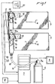
- the smudging-fluid dispensing apparatus is generally identified by reference numeral 1 . It is in particular intended for automatic cash dispensers known as “automatic teller machines (ATMs)". Such dispensers, in known manner, have an outer body with fixed walls provided with a light armour-plating. In Fig. 1 one of these walls is diagrammatically denoted at 2 .
- a dispenser Housed within the dispenser is at least one extractable casing or drawer 3 within which the banknotes to be supplied, upon request, to the dispenser's users are usually disposed.
- Two extractable casings or drawers 3 are shown by way of example in Figs. 1 and 2.
- Drawers 3 are housed in appropriate seatings of the dispenser. The position of complete insertion into these seatings which is coincident with the position for carrying out the operations for banknote supply to users, is the work position of drawers 3.
- the dispenser also has one or more doors for access to the inside thereof, in particular In order to enable execution of the different servicing operations and above all the periodical banknote supplies to drawers 3.
- drawers 3, optionally provided with a handle 4 are pulled out of their work position using a predetermined extraction direction, identified by 3a .
- Apparatus 1 comprises at least one dispensing vessel for the smudging fluid consisting of a liquid that can be atomised and is capable of leaving clear and indelible traces or marks.
- a single dispensing vessel is shown and it is defined by a bottle 5 under pressure provided at the top with a valve or a solenoid valve 5a . Also provided are channelling members 6 extending between the valve 5a and drawers 3.
- Electronic control and operation devices 7 receive signals in known manner from various detecting devices and sensors, diagrammatically identified by 8 , said devices or sensors for example detecting either opening or forcing or damaging of the dispenser walls 2.
- the electronic control and operation devices 7 also oversee dispensing of the smudging fluid, through operation of valve 5a for example, and switching on of alarm devices 9 known per se.
- the channelling members 6 extend from valve 5a through at least one piping that can fully or partly be a movable hose 10 of the flexible type, and/or a fixed pipe 11 of the rigid type.
- the channelling members 6 also have, at each drawer 3, at least one fitting length 12 which is rigid and movable and has a hooking position, corresponding to an operating position, in which drawers 3 and bottle 5 are operatively connected with each other.
- each fitting length 12 is movable towards and from a hooking position at which the smudging fluid can possibly reach the space at the inside of drawers 3.
- the smudging fluid directly enters the space within drawers 3, or it is distributed in said inner space by means of perforated tubular diffusers extending in the form of a pipe coil on the inner upper wall of drawers 3.
- couplers 13 placed at the fitting lengths which are of the male-female type for example, as better pointed out in the following.
- guide means 14 is provided which is rigid with the fitting lengths 12 and capable of imposing to the latter a predetermined guide trajectory 14a that at least at the end coincides with the extraction direction 3a of drawers 3 and enables the hooking position to be reached only when drawers 3 are in their work position.
- a passive-protection device integrated with the dispensing apparatus 1 is arranged.
- locking means 16 is provided which is supported in a rigid manner by fixed portions of the automatic dispenser and is adapted to fasten the fitting lengths 12 to their hooking position, in order to prevent both extraction of the fitting lengths 12 from the hooking position and extraction of drawers 3 from the work position.
- the locking means 16 acts on the fitting lengths 12 in such a manner that it simultaneously locks drawers 3 too.
- the locking means 16 acts on the fitting lengths 12 at a tailpiece 15 of said lengths.
- This tailpiece 15 has at least one seating or hole 17 for coupling with the locking means 16 and is engaged by said means when the fitting lengths 12 are in their hooking position.
- the locking means 16 may be either of the electromechanical type, or merely of the mechanical type, or in the form of a lock, a padlock or others.
- the locking means 16 is embodied by electromechanical cylinders having a rod insertable upon command into hole 17.
- the operation command for the cylinders is generated by the electronic control and operation devices 7 through an electric connection 18 .
- sensors 19 adapted to detect the correct mutual engagement of couplers 13 and therefore the correct insertion position of drawers 3 too, and capable of sending corresponding operating signals 20 to the electronic control and operation devices 7.
- sensors 19 are also connected with members signalling the operating conditions of the automatic dispensers, in particular with one or more warning indicators 21 .
- the channelling members 6 comprise a fixed pipe 11 extending vertically alongside drawers 3 and being fixed and rigid with a wall 2.
- Each fitting length 12 appears like an expansion 12a of a respective drawer 3 and is movable therewith.
- the guide means 14 of the fitting lengths 12 is embodied by the drawers 3 themselves with which expansions 12a are rigidly connected. Therefore the extraction direction 3a and guide trajectory 14a are substantially coincident and the work and hooking positions can be only simultaneously reached.
- expansions 12a extend laterally of drawers 3 as far as they project therefrom on the side where the fixed pipe 11 is located.
- Couplers 13 are arranged between the fixed pipe 11 and each expansion 12a.
- the mutual engagement position of couplers 13 is shown in solid lines in Fig. 3 and in the lower part of Fig. 2, where drawers 3 are in a work position.
- couplers 13 comprise male couplers 22 in engagement with expansions 12a and female couplers 23 in engagement with the fixed pipe 11.
- the female couplers 23 advantageously contain a valve element 23a inhibiting the smudging fluid flow when the male coupler 22 is not fitted.
- valve element 23a is diagrammatically shown in Figs. 3 and 5 and can be of the mechanical type, for example of a type, known per se, stopping outflow of air from tires.
- valve element 23a is in a relatively forward position, so that it can be deactivated in a priority manner to enable free passage of the smudging fluid, if said fluid is dispensed from bottle 5, as soon as the male couplers 22 are fitted.
- each female coupler 23 is externally provided with a sleeve 24 forming a holding chamber 24a adapted to keep compactness of the smudging fluid jet possibly dispensed when coupler 22 is fitted in an inaccurate manner.
- Sleeve 24 is maintained in a projecting and forward position with respect to the fixed pipe 11 by the action of spring means 25 .
- sleeve 24 is provided to keep a forward position to an extent sufficient to establish a contact with the respective fitting length 12 or a male coupler 22, as soon as the valve element 23a is opened.
- sensors 19 are electromechanical microswitches responsive to the sleeve position. It is however apparent that sensors 19 can be of various types, magnetic or optical sensors for example.
- Tailpiece 15 provided for a passive protection too, is a tab extension 15a of the fitting lengths 12 projecting in the direction of the fixed pipe 11, for example.
- the tab extension 15a can however follow any suitable direction.
- the locking means 16 for example defined by said electromechanical cylinders, can be fastened to the fixed pipe 11 or the adjacent wall 2 of the automatic dispenser, as well as to a any suitable position.
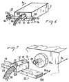
- the channelling members 6 comprise a movable pipe 10 and, at the end thereof, fitting lengths 12 defined by blocks 12b movable in front of drawers 3. Therefore blocks 12b are movable independently of drawers 3.
- the guide means 14 overseeing movements of blocks 12b are embodied by at least one bar 26 provided with a first end connected with an articulated joint 26a .
- Each fitting length 12 or block 12b is rigidly connected to bar 26 and the articulated joint 26a is formed for example at a wall 2 of the dispenser.
- the articulated joint 26a defines both the bar 26 trajectory and the trajectory of the fitting length 12, rigidly connected with bar 26.
- the articulated joint 26a defines a vertically-directed rotation axis 27 so that each fitting length 12 can carry out a translation along a guide trajectory 14a defined by a wide arc of a circumference extending in front of each drawer 3 at a work position and at the end substantially coinciding with the extraction direction 3a, as shown in Fig. 7.
- couplers 13 comprise a male coupler in engagement with drawers 3 and a female coupler formed in blocks 12b.
- each sensor 19 preferably consists of a magnetic field sensor responsive to the distance from a magnetic locator 19a surrounding the male coupler like a disk.
- Figs. 6 and 7 Connected with sensors 19 in the embodiment shown in Figs. 6 and 7 are signalling members or warning indicators 21 informing about an insufficient insertion or lack of insertion/hooking of drawers 3, said indicators being directly placed on each block 12b and consisting of a green LED (Light-Emitting Diode) to highlight a correct hooking situation and a red LED to highlight a wrong situation or an alarm.
- a green LED Light-Emitting Diode
- Tailpiece 15 for active protection is a crosspiece extension 15b of bar 26 extending beyond block 12b and terminating with an end portion having at least one hole 17 to be engaged by the locking means 16 supported by a wall 2 for example, and embodied by electromechanical cylinders provided with a rod insertable upon command into hole 17.
- the apparatus first of all ensures an active protection to the banknotes or valuables housed in drawers 3: in case of alarm it dispenses a fluid on said banknotes and valuables which is capable of leaving clear and indelible traces.
- the correct and real functional character of the apparatus is ensured through control of the correct insertion and positioning of the channelling members 6 and drawers 3.
- sensors 19 detect and signal every insufficient insertion of the fitting lengths 12.
- a complete insertion of the fitting lengths 12 is made possible if drawers 3 are not well positioned: in the case shown in Fig. 2 because the two operations are simultaneous, in the case shown in Fig. 7 because if the drawers are not thoroughly inserted in the work position the guide trajectory 14a is transverse to the male element 15.
- drawers 3 themselves form the guide means and determine positioning of the expansions 12a, whereas in the embodiment where the fitting lengths 12 are made up of blocks 12b, positioning is determined by the accurate rotation of a bar 26 around an articulated joint 26a.
- the alarm device 9 can be switched on.
- the detailed structure in Fig. 5 is a further assurance on the safety and functional character of the apparatus since, after switching on of the alarm device 9, also activation of the smudging-fluid dispenser is enabled in spite of the presence of insertion errors.
- valve elements 23a are opened in a priority manner so that passage of the smudging fluid is enabled even if the male elements 22 are not perfectly inserted in depth.
- the male elements 22 engage sleeve 24, against the action of the spring means 25. Therefore, even if the connecting elements 13 are only disposed close to each other, sleeves 24 embody holding chambers 24a for the jet that are sufficient to cause the fluid to flow into the fitting length 12- and into drawers 3- without leaks in the surrounding environment.
- valve element 23a is capable of preventing fluid flows when the drawers are completely pulled out, so that damages to the staff are avoided, should the smudging fluid be accidentally dispensed while drawers 3 are pulled out.
- Apparatus 1 also has a passive safety function, because the locking means 16 prevents extraction of drawers 3 in the absence of special procedures or conditions for deactivating the locking means 16.
- the invention achieves important advantages.
- the devised apparatus is capable of both making the operators' procedures greatly simpler and increasing the banknote and valuables containers' safety, in particular in case of automatic cash dispensers.
- the channelling members are in fact connected and disconnected in an automatic and easier manner that however does not enable connection of said channelling members if the drawers are not in the correct work position.
- the apparatus is also efficient as a passive protection and therefore maintains its utility in case of burglary even if the members conveying the smudging fluid are not activated.
Landscapes
- Physics & Mathematics (AREA)
- General Physics & Mathematics (AREA)
- Business, Economics & Management (AREA)
- Accounting & Taxation (AREA)
- Finance (AREA)
- Feeding, Discharge, Calcimining, Fusing, And Gas-Generation Devices (AREA)
- Quick-Acting Or Multi-Walled Pipe Joints (AREA)
- Control And Other Processes For Unpacking Of Materials (AREA)
- Vending Machines For Individual Products (AREA)
- Beverage Vending Machines With Cups, And Gas Or Electricity Vending Machines (AREA)
- Automatic Analysis And Handling Materials Therefor (AREA)
- Separation, Sorting, Adjustment, Or Bending Of Sheets To Be Conveyed (AREA)
- Control Of Vending Devices And Auxiliary Devices For Vending Devices (AREA)
Applications Claiming Priority (2)
| Application Number | Priority Date | Filing Date | Title |
|---|---|---|---|
| IT1999MI000484U IT246879Y1 (it) | 1999-07-28 | 1999-07-28 | Apparato di erogazione di un fluido macchiante per distributori automatici di banconote e valori |
| ITMI990484U | 1999-07-28 |
Publications (3)
| Publication Number | Publication Date |
|---|---|
| EP1073020A2 true EP1073020A2 (fr) | 2001-01-31 |
| EP1073020A3 EP1073020A3 (fr) | 2001-04-04 |
| EP1073020B1 EP1073020B1 (fr) | 2003-04-16 |
Family
ID=11382221
Family Applications (1)
| Application Number | Title | Priority Date | Filing Date |
|---|---|---|---|
| EP00112558A Expired - Lifetime EP1073020B1 (fr) | 1999-07-28 | 2000-06-14 | Dispositif distributeur de fluide de souillure, pour conteneurs de billets de banque et d'objets de valeur |
Country Status (6)
| Country | Link |
|---|---|
| US (1) | US6453828B1 (fr) |
| EP (1) | EP1073020B1 (fr) |
| AT (1) | ATE237856T1 (fr) |
| DE (1) | DE60002137T2 (fr) |
| ES (1) | ES2194650T3 (fr) |
| IT (1) | IT246879Y1 (fr) |
Cited By (3)
| Publication number | Priority date | Publication date | Assignee | Title |
|---|---|---|---|---|
| ITMI20091437A1 (it) * | 2009-08-07 | 2011-02-08 | M I B S P A | Apparato distributore di banconote e valori |
| GB2489946A (en) * | 2011-04-11 | 2012-10-17 | Spinnaker Int Ltd | A secure bag and secure container |
| GR1010222B (el) * | 2021-06-29 | 2022-04-14 | Divico-Ιδιωτικη Επιχειρηση Παροχης Υπηρεσιων Ασφαλειας Ανωνυμη Εταιρεια, | Ενεργητικη και παθητικη προστασια των χρηματων που βρισκονται στις κασετινες των ατμ απο εκρηξη η βιαιη μετακινηση του ατμ |
Families Citing this family (6)
| Publication number | Priority date | Publication date | Assignee | Title |
|---|---|---|---|---|
| GB2353067B (en) * | 1999-07-19 | 2001-07-18 | Spinnaker Int Ltd | Security cabinet,combined security unit and ATM pick unit,and ATM including such an arrangement |
| DE102007015382C5 (de) * | 2007-03-28 | 2019-08-14 | Sp Sicherheitsprodukte Vertriebs Gmbh | System zur Aufbewahrung von Wertgegenständen |
| DE102010016970A1 (de) * | 2010-05-17 | 2011-11-17 | Wincor Nixdorf International Gmbh | Vorrichtung zum Ungültigmachen von Wertscheinen |
| DE102012102223A1 (de) * | 2012-03-16 | 2013-09-19 | Wincor Nixdorf International Gmbh | Vorrichtung zum Ungültigmachen von Wertscheinen und Geldkassette mit einer solchen Vorrichtung |
| JP2014052896A (ja) * | 2012-09-07 | 2014-03-20 | Glory Ltd | カセット、紙幣処理装置および処理方法 |
| WO2015012759A1 (fr) * | 2013-07-26 | 2015-01-29 | Sqs Security Qube System Ab | Système pour le stockage et la destruction d'objets de valeur, et son procédé |
Family Cites Families (7)
| Publication number | Priority date | Publication date | Assignee | Title |
|---|---|---|---|---|
| US4018361A (en) * | 1976-02-17 | 1977-04-19 | Fegley Charles R | Fluid dispensing anti-burglar device |
| FR2595491B1 (fr) * | 1986-03-05 | 1988-06-17 | Boutroy Marc | Dispositif de securite pour le transport de documents de valeur |
| US5219196A (en) * | 1990-11-09 | 1993-06-15 | Luker Graham J | Locks |
| AU2341692A (en) * | 1991-07-19 | 1993-02-23 | Transalarm Limited | Document invalidation apparatus and trigger for operation thereof |
| US5598793A (en) * | 1993-06-17 | 1997-02-04 | Lopez, Jr.; Martin | ATM anti-theft device |
| US5787819A (en) * | 1996-07-30 | 1998-08-04 | M.I.B. Elettronica S.R.L. | Anti-effraction device, in particular for automatic dispensers of banknotes and valuables |
| GB9727515D0 (en) * | 1997-12-31 | 1998-02-25 | Spinnaker Int Ltd | Security system |
-
1999
- 1999-07-28 IT IT1999MI000484U patent/IT246879Y1/it active
-
2000
- 2000-06-14 AT AT00112558T patent/ATE237856T1/de not_active IP Right Cessation
- 2000-06-14 ES ES00112558T patent/ES2194650T3/es not_active Expired - Lifetime
- 2000-06-14 EP EP00112558A patent/EP1073020B1/fr not_active Expired - Lifetime
- 2000-06-14 DE DE60002137T patent/DE60002137T2/de not_active Expired - Lifetime
- 2000-06-16 US US09/595,019 patent/US6453828B1/en not_active Expired - Fee Related
Cited By (4)
| Publication number | Priority date | Publication date | Assignee | Title |
|---|---|---|---|---|
| ITMI20091437A1 (it) * | 2009-08-07 | 2011-02-08 | M I B S P A | Apparato distributore di banconote e valori |
| GB2489946A (en) * | 2011-04-11 | 2012-10-17 | Spinnaker Int Ltd | A secure bag and secure container |
| GB2489946B (en) * | 2011-04-11 | 2015-09-02 | Spinnaker Int Ltd | A secure bag and a secure container |
| GR1010222B (el) * | 2021-06-29 | 2022-04-14 | Divico-Ιδιωτικη Επιχειρηση Παροχης Υπηρεσιων Ασφαλειας Ανωνυμη Εταιρεια, | Ενεργητικη και παθητικη προστασια των χρηματων που βρισκονται στις κασετινες των ατμ απο εκρηξη η βιαιη μετακινηση του ατμ |
Also Published As
| Publication number | Publication date |
|---|---|
| ITMI990484U1 (it) | 2001-01-28 |
| EP1073020B1 (fr) | 2003-04-16 |
| DE60002137T2 (de) | 2003-12-11 |
| EP1073020A3 (fr) | 2001-04-04 |
| ITMI990484V0 (it) | 1999-07-28 |
| IT246879Y1 (it) | 2002-04-10 |
| DE60002137D1 (de) | 2003-05-22 |
| US6453828B1 (en) | 2002-09-24 |
| ES2194650T3 (es) | 2003-12-01 |
| ATE237856T1 (de) | 2003-05-15 |
Similar Documents
| Publication | Publication Date | Title |
|---|---|---|
| EP1073020B1 (fr) | Dispositif distributeur de fluide de souillure, pour conteneurs de billets de banque et d'objets de valeur | |
| US7503205B2 (en) | Redundant vacuum source for secondary containment monitoring and leak detection system and method | |
| US5057076A (en) | Infusion apparatus | |
| PL203267B1 (pl) | Perystaltyczna pompa infuzyjna | |
| FR2892799B1 (fr) | Dispositif de commande du remplissage et/ou du soutirage de fluide et reservoir comportant un tel dispositif | |
| KR970004745B1 (ko) | 액체송출장치 | |
| KR100384503B1 (ko) | 자동 급유장치 | |
| US8844587B1 (en) | Locking fuel pump dispenser | |
| EP0127147A2 (fr) | Dispositif empêchant le débordement pour un système de remplissage par liquide | |
| CA1093035A (fr) | Tete et installation de dosage de liquide | |
| CA2920717A1 (fr) | Dispositif d'accouplement | |
| WO1995009807A1 (fr) | Pistolet de distribution de carburant et de recuperation des vapeurs | |
| JPH0680197A (ja) | 希釈装置 | |
| US20190161370A1 (en) | Apparatus for and operation of a liquid flow circuit containing a chemical additive | |
| AU2017356172B2 (en) | Housing device for hoses of fire extinguishers and/or fire hydrants | |
| CA2221877C (fr) | Soupape de securite pour systeme d'alimentation en eau | |
| US4292995A (en) | Locking valve apparatus | |
| US5918766A (en) | Locking forecourt fuel pump | |
| US5755256A (en) | Automatic shutoff fueling system | |
| KR20190074034A (ko) | 소화약제 방출제어장치 및 이를 갖춘 자동소화설비 | |
| EP0715116B1 (fr) | Appareil d'injection d'un liquide pour une méthode de revêtement de la surface intérieure d'une conduite | |
| US20070034282A1 (en) | Hydraulic interlocking fuel nozzle | |
| WO1990003329A1 (fr) | Systeme de distribution d'additif | |
| GB2123110A (en) | Means and method of distribution in cip equipment | |
| KR200182577Y1 (ko) | 눈금 센스봉 기름보일러통 안전장치 |
Legal Events
| Date | Code | Title | Description |
|---|---|---|---|
| PUAI | Public reference made under article 153(3) epc to a published international application that has entered the european phase |
Free format text: ORIGINAL CODE: 0009012 |
|
| AK | Designated contracting states |
Kind code of ref document: A2 Designated state(s): AT BE CH CY DE DK ES FI FR GB GR IE IT LI LU MC NL PT SE |
|
| AX | Request for extension of the european patent |
Free format text: AL;LT;LV;MK;RO;SI |
|
| PUAL | Search report despatched |
Free format text: ORIGINAL CODE: 0009013 |
|
| AK | Designated contracting states |
Kind code of ref document: A3 Designated state(s): AT BE CH CY DE DK ES FI FR GB GR IE IT LI LU MC NL PT SE |
|
| AX | Request for extension of the european patent |
Free format text: AL;LT;LV;MK;RO;SI |
|
| RIC1 | Information provided on ipc code assigned before grant |
Free format text: 7G 07F 7/10 A, 7E 05G 1/14 B |
|
| AKX | Designation fees paid | ||
| 17P | Request for examination filed |
Effective date: 20011002 |
|
| RBV | Designated contracting states (corrected) |
Designated state(s): AT BE CH CY DE DK ES FI FR GB GR IE IT LI LU MC NL PT SE |
|
| REG | Reference to a national code |
Ref country code: DE Ref legal event code: 8566 |
|
| 17Q | First examination report despatched |
Effective date: 20020204 |
|
| GRAH | Despatch of communication of intention to grant a patent |
Free format text: ORIGINAL CODE: EPIDOS IGRA |
|
| GRAH | Despatch of communication of intention to grant a patent |
Free format text: ORIGINAL CODE: EPIDOS IGRA |
|
| GRAA | (expected) grant |
Free format text: ORIGINAL CODE: 0009210 |
|
| RAP1 | Party data changed (applicant data changed or rights of an application transferred) |
Owner name: M.I.B. S.P.A. |
|
| AK | Designated contracting states |
Designated state(s): AT BE CH CY DE DK ES FI FR GB GR IE IT LI LU MC NL PT SE |
|
| PG25 | Lapsed in a contracting state [announced via postgrant information from national office to epo] |
Ref country code: IT Free format text: LAPSE BECAUSE OF FAILURE TO SUBMIT A TRANSLATION OF THE DESCRIPTION OR TO PAY THE FEE WITHIN THE PRESCRIBED TIME-LIMIT;WARNING: LAPSES OF ITALIAN PATENTS WITH EFFECTIVE DATE BEFORE 2007 MAY HAVE OCCURRED AT ANY TIME BEFORE 2007. THE CORRECT EFFECTIVE DATE MAY BE DIFFERENT FROM THE ONE RECORDED. Effective date: 20030416 Ref country code: FI Free format text: LAPSE BECAUSE OF FAILURE TO SUBMIT A TRANSLATION OF THE DESCRIPTION OR TO PAY THE FEE WITHIN THE PRESCRIBED TIME-LIMIT Effective date: 20030416 Ref country code: NL Free format text: LAPSE BECAUSE OF FAILURE TO SUBMIT A TRANSLATION OF THE DESCRIPTION OR TO PAY THE FEE WITHIN THE PRESCRIBED TIME-LIMIT Effective date: 20030416 Ref country code: AT Free format text: LAPSE BECAUSE OF FAILURE TO SUBMIT A TRANSLATION OF THE DESCRIPTION OR TO PAY THE FEE WITHIN THE PRESCRIBED TIME-LIMIT Effective date: 20030416 |
|
| REG | Reference to a national code |
Ref country code: GB Ref legal event code: FG4D |
|
| REG | Reference to a national code |
Ref country code: CH Ref legal event code: EP |
|
| REF | Corresponds to: |
Ref document number: 60002137 Country of ref document: DE Date of ref document: 20030522 Kind code of ref document: P |
|
| REG | Reference to a national code |
Ref country code: IE Ref legal event code: FG4D |
|
| REG | Reference to a national code |
Ref country code: CH Ref legal event code: NV Representative=s name: BOVARD AG PATENTANWAELTE |
|
| PG25 | Lapsed in a contracting state [announced via postgrant information from national office to epo] |
Ref country code: CY Free format text: LAPSE BECAUSE OF FAILURE TO SUBMIT A TRANSLATION OF THE DESCRIPTION OR TO PAY THE FEE WITHIN THE PRESCRIBED TIME-LIMIT Effective date: 20030614 Ref country code: LU Free format text: LAPSE BECAUSE OF NON-PAYMENT OF DUE FEES Effective date: 20030614 |
|
| PG25 | Lapsed in a contracting state [announced via postgrant information from national office to epo] |
Ref country code: IE Free format text: LAPSE BECAUSE OF NON-PAYMENT OF DUE FEES Effective date: 20030616 |
|
| PG25 | Lapsed in a contracting state [announced via postgrant information from national office to epo] |
Ref country code: MC Free format text: LAPSE BECAUSE OF NON-PAYMENT OF DUE FEES Effective date: 20030630 |
|
| PG25 | Lapsed in a contracting state [announced via postgrant information from national office to epo] |
Ref country code: PT Free format text: LAPSE BECAUSE OF FAILURE TO SUBMIT A TRANSLATION OF THE DESCRIPTION OR TO PAY THE FEE WITHIN THE PRESCRIBED TIME-LIMIT Effective date: 20030716 Ref country code: GR Free format text: LAPSE BECAUSE OF FAILURE TO SUBMIT A TRANSLATION OF THE DESCRIPTION OR TO PAY THE FEE WITHIN THE PRESCRIBED TIME-LIMIT Effective date: 20030716 Ref country code: SE Free format text: LAPSE BECAUSE OF FAILURE TO SUBMIT A TRANSLATION OF THE DESCRIPTION OR TO PAY THE FEE WITHIN THE PRESCRIBED TIME-LIMIT Effective date: 20030716 Ref country code: DK Free format text: LAPSE BECAUSE OF FAILURE TO SUBMIT A TRANSLATION OF THE DESCRIPTION OR TO PAY THE FEE WITHIN THE PRESCRIBED TIME-LIMIT Effective date: 20030716 |
|
| NLV1 | Nl: lapsed or annulled due to failure to fulfill the requirements of art. 29p and 29m of the patents act | ||
| ET | Fr: translation filed | ||
| PLBQ | Unpublished change to opponent data |
Free format text: ORIGINAL CODE: EPIDOS OPPO |
|
| PLBI | Opposition filed |
Free format text: ORIGINAL CODE: 0009260 |
|
| PLAX | Notice of opposition and request to file observation + time limit sent |
Free format text: ORIGINAL CODE: EPIDOSNOBS2 |
|
| 26 | Opposition filed |
Opponent name: NCR INTERNATIONAL INC. Effective date: 20040112 |
|
| REG | Reference to a national code |
Ref country code: IE Ref legal event code: MM4A |
|
| PGFP | Annual fee paid to national office [announced via postgrant information from national office to epo] |
Ref country code: CH Payment date: 20040611 Year of fee payment: 5 |
|
| PLBB | Reply of patent proprietor to notice(s) of opposition received |
Free format text: ORIGINAL CODE: EPIDOSNOBS3 |
|
| PGFP | Annual fee paid to national office [announced via postgrant information from national office to epo] |
Ref country code: BE Payment date: 20040705 Year of fee payment: 5 |
|
| PG25 | Lapsed in a contracting state [announced via postgrant information from national office to epo] |
Ref country code: BE Free format text: LAPSE BECAUSE OF NON-PAYMENT OF DUE FEES Effective date: 20050630 Ref country code: CH Free format text: LAPSE BECAUSE OF NON-PAYMENT OF DUE FEES Effective date: 20050630 Ref country code: LI Free format text: LAPSE BECAUSE OF NON-PAYMENT OF DUE FEES Effective date: 20050630 |
|
| REG | Reference to a national code |
Ref country code: CH Ref legal event code: PL |
|
| PLCK | Communication despatched that opposition was rejected |
Free format text: ORIGINAL CODE: EPIDOSNREJ1 |
|
| PLBN | Opposition rejected |
Free format text: ORIGINAL CODE: 0009273 |
|
| STAA | Information on the status of an ep patent application or granted ep patent |
Free format text: STATUS: OPPOSITION REJECTED |
|
| 27O | Opposition rejected |
Effective date: 20070705 |
|
| BERE | Be: lapsed |
Owner name: *MIB S.P.A. Effective date: 20050630 |
|
| PLAB | Opposition data, opponent's data or that of the opponent's representative modified |
Free format text: ORIGINAL CODE: 0009299OPPO |
|
| PGFP | Annual fee paid to national office [announced via postgrant information from national office to epo] |
Ref country code: ES Payment date: 20110629 Year of fee payment: 12 |
|
| REG | Reference to a national code |
Ref country code: ES Ref legal event code: FD2A Effective date: 20131030 |
|
| PG25 | Lapsed in a contracting state [announced via postgrant information from national office to epo] |
Ref country code: ES Free format text: LAPSE BECAUSE OF NON-PAYMENT OF DUE FEES Effective date: 20120615 |
|
| REG | Reference to a national code |
Ref country code: FR Ref legal event code: PLFP Year of fee payment: 17 |
|
| REG | Reference to a national code |
Ref country code: FR Ref legal event code: PLFP Year of fee payment: 18 |
|
| PGFP | Annual fee paid to national office [announced via postgrant information from national office to epo] |
Ref country code: DE Payment date: 20170613 Year of fee payment: 18 Ref country code: GB Payment date: 20170614 Year of fee payment: 18 Ref country code: FR Payment date: 20170628 Year of fee payment: 18 |
|
| REG | Reference to a national code |
Ref country code: DE Ref legal event code: R119 Ref document number: 60002137 Country of ref document: DE |
|
| GBPC | Gb: european patent ceased through non-payment of renewal fee |
Effective date: 20180614 |
|
| PG25 | Lapsed in a contracting state [announced via postgrant information from national office to epo] |
Ref country code: DE Free format text: LAPSE BECAUSE OF NON-PAYMENT OF DUE FEES Effective date: 20190101 Ref country code: GB Free format text: LAPSE BECAUSE OF NON-PAYMENT OF DUE FEES Effective date: 20180614 Ref country code: FR Free format text: LAPSE BECAUSE OF NON-PAYMENT OF DUE FEES Effective date: 20180630 |