EP1073076A2 - Signalgeber, insbesondere Druck- oder Unterdrucksensor - Google Patents
Signalgeber, insbesondere Druck- oder Unterdrucksensor Download PDFInfo
- Publication number
- EP1073076A2 EP1073076A2 EP00113448A EP00113448A EP1073076A2 EP 1073076 A2 EP1073076 A2 EP 1073076A2 EP 00113448 A EP00113448 A EP 00113448A EP 00113448 A EP00113448 A EP 00113448A EP 1073076 A2 EP1073076 A2 EP 1073076A2
- Authority
- EP
- European Patent Office
- Prior art keywords
- profile element
- signal generator
- membrane
- generator according
- chambers
- Prior art date
- Legal status (The legal status is an assumption and is not a legal conclusion. Google has not performed a legal analysis and makes no representation as to the accuracy of the status listed.)
- Withdrawn
Links
Images

Classifications
-
- H—ELECTRICITY
- H01—ELECTRIC ELEMENTS
- H01H—ELECTRIC SWITCHES; RELAYS; SELECTORS; EMERGENCY PROTECTIVE DEVICES
- H01H3/00—Mechanisms for operating contacts
- H01H3/22—Power arrangements internal to the switch for operating the driving mechanism
- H01H3/24—Power arrangements internal to the switch for operating the driving mechanism using pneumatic or hydraulic actuator
-
- E—FIXED CONSTRUCTIONS
- E05—LOCKS; KEYS; WINDOW OR DOOR FITTINGS; SAFES
- E05F—DEVICES FOR MOVING WINGS INTO OPEN OR CLOSED POSITION; CHECKS FOR WINGS; WING FITTINGS NOT OTHERWISE PROVIDED FOR, CONCERNED WITH THE FUNCTIONING OF THE WING
- E05F15/00—Power-operated mechanisms for wings
- E05F15/40—Safety devices, e.g. detection of obstructions or end positions
- E05F15/42—Detection using safety edges
- E05F15/47—Detection using safety edges responsive to changes in fluid pressure
-
- E—FIXED CONSTRUCTIONS
- E05—LOCKS; KEYS; WINDOW OR DOOR FITTINGS; SAFES
- E05F—DEVICES FOR MOVING WINGS INTO OPEN OR CLOSED POSITION; CHECKS FOR WINGS; WING FITTINGS NOT OTHERWISE PROVIDED FOR, CONCERNED WITH THE FUNCTIONING OF THE WING
- E05F15/00—Power-operated mechanisms for wings
- E05F15/40—Safety devices, e.g. detection of obstructions or end positions
- E05F15/42—Detection using safety edges
- E05F2015/487—Fault detection of safety edges
-
- H—ELECTRICITY
- H01—ELECTRIC ELEMENTS
- H01H—ELECTRIC SWITCHES; RELAYS; SELECTORS; EMERGENCY PROTECTIVE DEVICES
- H01H3/00—Mechanisms for operating contacts
- H01H3/02—Operating parts, i.e. for operating driving mechanism by a mechanical force external to the switch
- H01H3/14—Operating parts, i.e. for operating driving mechanism by a mechanical force external to the switch adapted for operation by a part of the human body other than the hand, e.g. by foot
- H01H3/141—Cushion or mat switches
- H01H2003/148—Cushion or mat switches the mat switch being composed by independently juxtaposed contact tiles, e.g. for obtaining a variable protected area
-
- H—ELECTRICITY
- H01—ELECTRIC ELEMENTS
- H01H—ELECTRIC SWITCHES; RELAYS; SELECTORS; EMERGENCY PROTECTIVE DEVICES
- H01H3/00—Mechanisms for operating contacts
- H01H3/02—Operating parts, i.e. for operating driving mechanism by a mechanical force external to the switch
- H01H3/14—Operating parts, i.e. for operating driving mechanism by a mechanical force external to the switch adapted for operation by a part of the human body other than the hand, e.g. by foot
- H01H3/141—Cushion or mat switches
- H01H3/142—Cushion or mat switches of the elongated strip type
Definitions
- the present invention relates to a signal generator, in particular pressure or vacuum signal transmitter for Protection of pinching points for mechanically operated Doors, gates or the like, as well as for switching elements, Safety edges, safety mats or the like.
- a signal generator in particular pressure or vacuum signal transmitter for Protection of pinching points for mechanically operated Doors, gates or the like, as well as for switching elements, Safety edges, safety mats or the like.
- Profile element in particular hollow profile element.
- Such signal generators consist essentially of one Profile element, in particular hollow profile element with a Chamber, which is located in the longitudinal direction in the profile element extends. For example, a is attached to this chamber Pressure sensor connected.
- the present invention is therefore based on the object based on a signal generator of the type mentioned create, which eliminates the disadvantages mentioned and with which in a very simple and inexpensive way Security in operation permanently with increased security can be checked.
- At least one Profile element is formed from at least two chambers.
- These two chambers are preferably continuous in one Profile element, especially in a hollow profile element arranged one above the other and running in the longitudinal direction intended. In the end these can be connected to each other be, but this to the outside towards an environment are closed.
- these two chambers can each Connect connections, one connection for one Pressure sensor and another connection for a pulse generator is provided.
- the pulse generator can generate permanent signals in the Send operation through the auto switch and this way check it for leaks and functionality. These test signals are measured in the pressure sensor. The Test signal completely passes through the signal generator.
- a membrane chamber is then connected to the membrane formed, which is preferably open at the end.
- side openings in the Membrane chamber to be provided to equalize the pressure guarantee.
- the membrane can and can be elastic at least partially formed from one of the two chambers his. There is no limit to the invention here.
- the present inventive concept also includes that Arrange chambers one above the other or even side by side.
- the profile element is preferably arcuate and provided with a flat base.
- Hollow sections can have multiple chambers with or without a membrane be arranged.
- the profile element can be rectangular and elongated very flat to make one To create signal generator, which, for example, also for Safety mats or narrow safety edges is suitable.
- the individual chambers can be placed side by side or be arranged one above the other. You can also influence take the actuation behavior of the signal generator by for example the cross section of the individual chambers round, is oval or rectangular.
- an oval chamber is formed, the is arranged perpendicular to the direction of actuation, so results by squeezing the oval trained chamber a cross-sectional enlargement what generates a negative pressure as a switching signal.
- a corresponding vacuum signal on one Vacuum sensor can be measured or recognized.
- Corresponding negative pressure and / or positive pressure signals can then assume a pulse generator in operation to check the functionality of the signal generator. This should also with the present inventive concept be included.
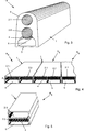
- a signal transmitter R 1 is essentially formed from a profile element 1, which preferably has an elongated hollow profile element inside, two continuous chambers 2.1, 2.2 lying one above the other.
- the chamber 2.1 is preferably a flow and the chamber 2.2 formed as a return line in the profile element 1.
- the profile element 1 is preferably of an elastic type and can be formed from a rubber element. With a Base area 3 can be on any object be determined.
- the chambers 2.1, 2.2 are preferred arranged one above the other in the profile element 1. These run continuously in the longitudinal direction of the profile element 1. Die Chambers 2.1, 2.2 are airtight when viewed individually formed from the profile element 1.
- the profile element 1 can manufactured in any length or on a any desired length can be cut to length.
- a further signal transmitter R 2 is shown, in which, in the manner described above, the profile element 1 has two chambers 2.1, 2.2, which are preferably arranged one above the other.
- the difference is that the chamber 2.2 through a membrane 4 is divided and forms a membrane chamber 5, which is open at each end.
- a signal transmitter R 3 is shown, which likewise consists of a profile element 1, in which a chamber 2.1 is provided opposite the base area 3, which corresponds approximately to an outer, arch-like contour 6 of the profile element.
- Membrane 4 connects to chamber 2.1 and divides profile element 1 into a further chamber 2.2 and / or membrane chamber 5.
- the membrane chamber 5 can be opened at the front or to be introverted. This will be discussed in more detail later.
- FIG. 3 shows a signal transmitter R 4 , in which the chambers 2.1, 2.2 according to FIG. 1 are arranged, a further membrane chamber 5 adjoining the chamber 2.2, which is preferably open at the end.
- a signal transmitter R 5 is shown, the profile element 1 of which is preferably of rectangular cross section and very flat.
- the chambers 2.1, 2.2 above a membrane 4 are arranged side by side, with below the Membrane the membrane chamber 5 is formed. This too can front, preferably open. It has proven favorable, a plurality of such Arrange profile elements 1 side by side to form a surface to create.
- Corresponding signal generators can for example as components of a switch mat or the like. serve.
- FIG. 5 shows a similar signal transmitter R 6 according to FIG. 4, with the difference that the individual chambers 2.1, 2.2 are arranged one above the other.
- the membrane 4 and a membrane chamber 5 are connected to the chamber 2.2.
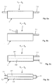
- the signal transmitters R 1 to R 6 described above are assigned connections 7.1, 7.2 on the end face or as desired along the profile element 1.
- Connections 7.1, 7.2 on one end or both ends to provide.
- Connection 7.1 preferably engages, as is the case, for example is shown in Figure 6c, in a chamber 2.1, wherein a further connection 7.2 opens into a chamber 2.2.
- the connections 7.1 to 7.2 are inserted at one end into the chamber 2.1, 2.2 in the manner described above, the other end of the chambers 2.1, 2.2 being sealed airtight to an environment and by means of a bridging 8 are connected.
- a profile element according to the invention has in one preferred embodiment two chambers, which are preferably arranged one above the other.
- the chambers are throughout in the profile element as through openings educated.
- the two connections 7.1, 7.2 serve, on the one hand a pressure sensor and on the other hand a pulse generator to connect.
- the pressure sensor receives a corresponding signal when Squeeze or mechanically operate the Profile element 1, for example when opening or closing a door, a gate or the like. Simultaneously can into the second chamber 2.1 through the connector
- the pulse generator emits permanent impulses on the Profile element 1 there. This allows the complete Signal generator, in particular the complete profile element 1 be checked for leaks with both chambers 2.1, 2.2.
- the two chambers 2.1, 2.2 preferably face pressure fluctuations, in particular a pressure increase caused by a Temperature increase, compensated by the membrane 4 become when the subsequent membrane chamber 5 for Environment, preferably open at the front.
- a particularly effective embodiment of the invention is given if, on the one hand, the chamber 2.1 is designed as a flow line and the chamber 2.2 as a return line, which are connected to one another on the one hand.
- the complete profile element or the complete chambers 2.1, 2.2 can be flowed through on the one hand by the switching signal, which is mechanically applied from the outside, and on the other hand by a permanent test signal, which is also routed to the same pressure sensor.
- the permanent test signal permanently checks and guarantees the functionality and functional safety in operation. Therefore, for the exemplary embodiment according to FIG. 1 and for the exemplary embodiment with the corresponding membrane, separate protection is sought in the subordinate claim.
Landscapes
- Physics & Mathematics (AREA)
- Fluid Mechanics (AREA)
- Measuring Fluid Pressure (AREA)
- Power-Operated Mechanisms For Wings (AREA)
Abstract
Description
| Positionszahlenliste | |||||
| 1 | Profilelement | 34 | 67 | ||
| 2 | Kammer | 35 | 68 | ||
| 3 | Grundfläche | 36 | 69 | ||
| 4 | Membran | 37 | 70 | ||
| 5 | Membrankammer | 38 | 71 | ||
| 6 | Kontur | 39 | 72 | ||
| 7 | Anschluss | 40 | 73 | ||
| 8 | Überbrückung | 41 | 74 | ||
| 9 | 42 | 75 | |||
| 10 | 43 | 76 | |||
| 11 | 44 | 77 | |||
| 12 | 45 | 78 | |||
| 13 | 46 | 79 | |||
| 14 | 47 | ||||
| 15 | 48 | R1 | Signalgeber | ||
| 16 | 49 | R2 | " | ||
| 17 | 50 | R3 | " | ||
| 18 | 51 | R4 | " | ||
| 19 | 52 | R5 | " | ||
| 20 | 53 | R6 | " | ||
| 21 | 54 | ||||
| 22 | 55 | ||||
| 23 | 56 | ||||
| 24 | 57 | ||||
| 25 | 58 | ||||
| 26 | 59 | ||||
| 27 | 60 | ||||
| 28 | 61 | ||||
| 29 | 62 | ||||
| 30 | 63 | ||||
| 31 | 64 | ||||
| 32 | 65 | ||||
| 33 | 66 |
Claims (13)
- Signalgeber, insbesondere Druck- oder Unterdrucksignalgeber zur Absicherung von Einklemmstellen, bei mechanisch betätigten Türen, Toren od. dgl. sowie für Schaltelemente, Schaltleisten, Schaltmatten od. dgl. mit zumindest einem Profilelement (1), insbesondere Hohlprofilelement,
dadurch gekennzeichnet,
dass das zumindest eine Profilelement (1) aus wenigstens zwei Kammern (2) gebildet ist. - Signalgeber, insbesondere Druck- oder Unterdrucksignalgeber zur Absicherung von Einklemmstellen, bei mechanisch betätigten Türen, Toren od. dgl. sowie für Schaltelemente, Schaltleisten, Schaltmatten od. dgl. mit zumindest einem Profilelement (1), insbesondere Hohlprofilelement, dadurch gekennzeichnet, dass zumindest eine Kammer (2.1, 2.2) des zumindest einen Profilelementes (1) zumindest teilweise als Membran (4) ausgebildet ist.
- Signalgeber nach Anspruch 1 oder 2, dadurch gekennzeichnet, dass das Profilelement (1) als ein elastisches, gummiartiges und längliches Hohlprofilelement ausgebildet ist.
- Signalgeber nach wenigstens einem der Ansprüche 1 bis 3, dadurch gekennzeichnet, dass die Kammern (2.1, 2.2) nebeneinander oder übereinander im Hohlprofilelement angeordnet sind.
- Signalgeber nach wenigstens einem der Ansprüche 1 bis 4, dadurch gekennzeichnet, dass die Kammern (2.1, 2.2) querschnittlich rund, oval oder rechteckartig ausgebildet sind.
- Signalgeber nach wenigstens einem der Ansprüche 1 bis 5, dadurch gekennzeichnet, dass die Kammern (2.1, 2.2) als Vor- oder als Rückleitungen ausgebildet sind.
- Signalgeber nach wenigstens einem der Ansprüche 1 bis 6, dadurch gekennzeichnet, dass die Kammern (2.1, 2.2) einends verschlossen und andernends miteinander in Verbindung stehen.
- Signalgeber nach wenigstens einem der Ansprüche 1 bis 7, dadurch gekennzeichnet, dass an die zumindest eine Kammer (2.1, 2.2) zumindest ein Ansschluss (7.1, 7.2) für eine Prüf- und/oder Messleitung vorgesehen ist
- Signalgeber nach Anspruch 8, dadurch gekennzeichnet, das jeder Kammer (2.1, 2.2) einends die Anschlüsse (7.1, 7.2) zugeordnet sind, wobei andernends die Kammern (2.1, 2.2) miteinander verbunden sind.
- Signalgeber nach wenigstens einem der Ansprüche 2 bis 9, dadurch gekennzeichnet, dass an die zumindest eine Membran (4) eine Membrankammer (5) anschliesst.
- Signalgeber nach Anspruch 10, dadurch gekennzeichnet, dass die Membrankammer (5) zu einer Umgebung geöffnet, insbesondere stirnseitig geöffnet ist.
- Signalgeber nach wenigstens einem der Ansprüche 2 bis 11, dadurch gekennzeichnet, dass die Membran (4) elastisch und in Längsrichtung aus dem Profilelement (1) gebildet ist.
- Signalgeber nach Anspruch 12, dadurch gekennzeichnet, dass die Membran (4) steifer als eine Membran eines an das Profilelement (1) angeschlossenen Drucksensors ausgebildet ist.
Applications Claiming Priority (2)
| Application Number | Priority Date | Filing Date | Title |
|---|---|---|---|
| DE19934828A DE19934828A1 (de) | 1999-07-24 | 1999-07-24 | Signalgeber, insbesondere Druck- oder Unterdrucksensor |
| DE19934828 | 1999-07-24 |
Publications (2)
| Publication Number | Publication Date |
|---|---|
| EP1073076A2 true EP1073076A2 (de) | 2001-01-31 |
| EP1073076A3 EP1073076A3 (de) | 2002-07-24 |
Family
ID=7915960
Family Applications (1)
| Application Number | Title | Priority Date | Filing Date |
|---|---|---|---|
| EP00113448A Withdrawn EP1073076A3 (de) | 1999-07-24 | 2000-06-24 | Signalgeber, insbesondere Druck- oder Unterdrucksensor |
Country Status (2)
| Country | Link |
|---|---|
| EP (1) | EP1073076A3 (de) |
| DE (1) | DE19934828A1 (de) |
Families Citing this family (2)
| Publication number | Priority date | Publication date | Assignee | Title |
|---|---|---|---|---|
| DE19958046B4 (de) * | 1999-12-03 | 2005-07-28 | Hübner GmbH | Fingerschutzprofil für eine Tür |
| DE10159586A1 (de) * | 2001-02-08 | 2002-08-14 | Marantec Antrieb Steuerung | Sicherheitsvorrichtung zum Anhalten motorisch bewegter Gegenstände |
Family Cites Families (8)
| Publication number | Priority date | Publication date | Assignee | Title |
|---|---|---|---|---|
| CH557949A (de) * | 1973-10-02 | 1975-01-15 | Bircher Max | Elektropneumatische schaltanordnung, insbesondere zum oeffnen eines tores, mit sicherheitssteuerung. |
| CH581249A5 (de) * | 1974-04-03 | 1976-10-29 | Alusuisse | |
| SE391831B (sv) * | 1975-11-12 | 1977-02-28 | Hallen J A | Tryckgivare i form av en kontaktskena for dorrar och liknande |
| DE3214838A1 (de) * | 1982-04-21 | 1983-10-27 | Hübner Gummi- und Kunststoff GmbH, 3500 Kassel | Kontaktmatte |
| DE3633834A1 (de) * | 1985-12-18 | 1987-06-25 | Neukirchen W U H Gmbh Co Kg | Schliesskantensicherung fuer kraftbetaetigte fenster, tueren und tore |
| DE3545057A1 (de) * | 1985-12-19 | 1987-07-02 | Hoermann Kg Antrieb Steuertec | Unfallschutzleiste |
| DE3636596A1 (de) * | 1986-10-28 | 1988-05-05 | Huegle Pfullendorf Kipptor | Vorrichtung und verfahren zur absicherung von kraftbetaetigten toren, tueren, fenster insbesondere von garagentoren |
| DE3921641A1 (de) * | 1989-06-30 | 1991-01-24 | Hoermann Kg Antrieb Steuertec | Sicherungsgeraet fuer die schliesskante eines torblattes |
-
1999
- 1999-07-24 DE DE19934828A patent/DE19934828A1/de not_active Withdrawn
-
2000
- 2000-06-24 EP EP00113448A patent/EP1073076A3/de not_active Withdrawn
Also Published As
| Publication number | Publication date |
|---|---|
| DE19934828A1 (de) | 2001-01-25 |
| EP1073076A3 (de) | 2002-07-24 |
Similar Documents
| Publication | Publication Date | Title |
|---|---|---|
| EP3348980B1 (de) | Mehrschichtiger, taktiler sensor mit befestigungsmittel | |
| DE202018106851U1 (de) | Trinkhalm | |
| EP4030031A1 (de) | Abschirmvorrichtung | |
| EP2628879A1 (de) | Rahmenanschlusselement | |
| EP3847332A1 (de) | Schutzvorrichtung für einen türflügel für ein fahrzeug und türvorrichtung für ein fahrzeug | |
| EP1520953A2 (de) | Vorsatztür oder -fenster, insbesondere Insektenschutztür oder -fenster | |
| EP1073076A2 (de) | Signalgeber, insbesondere Druck- oder Unterdrucksensor | |
| EP1111633B1 (de) | Fingerschutzprofil für eine Tür | |
| EP1568833B1 (de) | Schliessblech für ein Fenster oder eine Tür | |
| DE3712737C2 (de) | ||
| EP3112577A1 (de) | Absenkdichtung | |
| DE102021209490A1 (de) | Aufprallsensor mit einem deformierbaren Hohlkörper mit einer Vielzahl von Hohlkammern | |
| DE19828186A1 (de) | Gelenkeinrichtung, insbesondere für Rolladen- oder Falttürelemente, und Roll- oder Faltvorhang | |
| DE102016216835A1 (de) | Aushebesicherung für einen verschiebbaren und zum Verschieben anhebbaren Flügel | |
| DE19700707C2 (de) | Türblatt | |
| DE3411198C2 (de) | ||
| DE202011004097U1 (de) | Rahmenanordnung mit wenigstens einem Rahmenanschlusselement | |
| DE102011010773A1 (de) | Rahmenkonstruktion für ein Fenster oder eine Tür | |
| DE8423562U1 (de) | Scharnier | |
| EP2774795A2 (de) | Elastisches Hohlprofil und Innenschwenktüre mit einem elastischen Hohlprofil | |
| DE202013105887U1 (de) | Blendrahmen eines Fenster- oder Türrahmens | |
| DE218165C (de) | ||
| DE3248286A1 (de) | Verbundprofil fuer fenster und/oder tueren | |
| DE1962905C3 (de) | Beschlag für Fenster, Türen o.dgl | |
| DE19609480B4 (de) | Kabelkanaldeckel |
Legal Events
| Date | Code | Title | Description |
|---|---|---|---|
| PUAI | Public reference made under article 153(3) epc to a published international application that has entered the european phase |
Free format text: ORIGINAL CODE: 0009012 |
|
| AK | Designated contracting states |
Kind code of ref document: A2 Designated state(s): AT BE CH CY DE DK ES FI FR GB GR IE IT LI LU MC NL PT SE |
|
| AX | Request for extension of the european patent |
Free format text: AL;LT;LV;MK;RO;SI |
|
| PUAL | Search report despatched |
Free format text: ORIGINAL CODE: 0009013 |
|
| AK | Designated contracting states |
Kind code of ref document: A3 Designated state(s): AT BE CH CY DE DK ES FI FR GB GR IE IT LI LU MC NL PT SE |
|
| AX | Request for extension of the european patent |
Free format text: AL;LT;LV;MK;RO;SI |
|
| RIC1 | Information provided on ipc code assigned before grant |
Free format text: 7H 01H 3/24 A, 7H 01H 3/14 B, 7E 05F 15/00 B, 7F 16P 3/12 B |
|
| 17P | Request for examination filed |
Effective date: 20020919 |
|
| 17Q | First examination report despatched |
Effective date: 20021119 |
|
| STAA | Information on the status of an ep patent application or granted ep patent |
Free format text: STATUS: THE APPLICATION HAS BEEN WITHDRAWN |
|
| 18W | Application withdrawn |
Effective date: 20030113 |