EP1073161A2 - Fiche de courant à protection différentielle - Google Patents
Fiche de courant à protection différentielle Download PDFInfo
- Publication number
- EP1073161A2 EP1073161A2 EP20000810638 EP00810638A EP1073161A2 EP 1073161 A2 EP1073161 A2 EP 1073161A2 EP 20000810638 EP20000810638 EP 20000810638 EP 00810638 A EP00810638 A EP 00810638A EP 1073161 A2 EP1073161 A2 EP 1073161A2
- Authority
- EP
- European Patent Office
- Prior art keywords
- plug
- support body
- contact
- test
- conductor
- Prior art date
- Legal status (The legal status is an assumption and is not a legal conclusion. Google has not performed a legal analysis and makes no representation as to the accuracy of the status listed.)
- Withdrawn
Links
Images


Classifications
-
- H—ELECTRICITY
- H01—ELECTRIC ELEMENTS
- H01R—ELECTRICALLY-CONDUCTIVE CONNECTIONS; STRUCTURAL ASSOCIATIONS OF A PLURALITY OF MUTUALLY-INSULATED ELECTRICAL CONNECTING ELEMENTS; COUPLING DEVICES; CURRENT COLLECTORS
- H01R13/00—Details of coupling devices of the kinds covered by groups H01R12/70 or H01R24/00 - H01R33/00
- H01R13/66—Structural association with built-in electrical component
- H01R13/665—Structural association with built-in electrical component with built-in electronic circuit
- H01R13/6666—Structural association with built-in electrical component with built-in electronic circuit with built-in overvoltage protection
-
- H—ELECTRICITY
- H01—ELECTRIC ELEMENTS
- H01R—ELECTRICALLY-CONDUCTIVE CONNECTIONS; STRUCTURAL ASSOCIATIONS OF A PLURALITY OF MUTUALLY-INSULATED ELECTRICAL CONNECTING ELEMENTS; COUPLING DEVICES; CURRENT COLLECTORS
- H01R13/00—Details of coupling devices of the kinds covered by groups H01R12/70 or H01R24/00 - H01R33/00
- H01R13/66—Structural association with built-in electrical component
- H01R13/70—Structural association with built-in electrical component with built-in switch
- H01R13/713—Structural association with built-in electrical component with built-in switch the switch being a safety switch
- H01R13/7135—Structural association with built-in electrical component with built-in switch the switch being a safety switch with ground fault protector
-
- H—ELECTRICITY
- H01—ELECTRIC ELEMENTS
- H01H—ELECTRIC SWITCHES; RELAYS; SELECTORS; EMERGENCY PROTECTIVE DEVICES
- H01H83/00—Protective switches, e.g. circuit-breaking switches, or protective relays operated by abnormal electrical conditions otherwise than solely by excess current
- H01H83/02—Protective switches, e.g. circuit-breaking switches, or protective relays operated by abnormal electrical conditions otherwise than solely by excess current operated by earth fault currents
- H01H83/04—Protective switches, e.g. circuit-breaking switches, or protective relays operated by abnormal electrical conditions otherwise than solely by excess current operated by earth fault currents with testing means for indicating the ability of the switch or relay to function properly
-
- H—ELECTRICITY
- H05—ELECTRIC TECHNIQUES NOT OTHERWISE PROVIDED FOR
- H05K—PRINTED CIRCUITS; CASINGS OR CONSTRUCTIONAL DETAILS OF ELECTRIC APPARATUS; MANUFACTURE OF ASSEMBLAGES OF ELECTRICAL COMPONENTS
- H05K1/00—Printed circuits
- H05K1/18—Printed circuits structurally associated with non-printed electric components
Definitions
- the invention is based on a plug-in device protected against residual current according to the introductory part of claim 1.
- Residual current protected Prevent connectors such as safety plugs and safety sockets Electrical accidents and fires in electrical systems. They monitor infected people Consumers continuously and cut off the power supply before going to earth flowing fault current can be dangerous for people, animals or things.
- the invention relates to a prior art, such as that described in EP 0 641 045 B1 is described.
- a specified in this document and as a socket trained fault current protected plug-in device has a box-shaped housing on, in which a residual current circuit breaker is plugged together from modular units and a plug contact part are arranged. Executed as bushings Plug connections for a power consumer and actuators for a Contact arrangement of the residual current circuit breaker and for a test circuit led from the inside of the housing to the front of the socket. The case points on the back a power connector for connection to the conductor of a Low voltage network.
- this outlet When making this outlet, first be on the rear of a plate-shaped support body modular units one Contact arrangement, a drive, a test circuit and the mains connection fitted and by plugging into a part of the housing designed as a socket fixed. Remaining modular units of the drive and the test circuit as well as a Total current transformer, a magnetic release, a circuit and the plug contact part are housed on the front of the support body in the box and the box with a guaranteeing access to actuators and plug contacts Lid closed.
- the manufacture and maintenance of such an outlet requires a relatively large number of assembly steps. This is mainly because access to many of the modular units only after disassembly multiple modules is possible.
- the object of the invention is as set out in the claims based on specifying a fault-current protected plug device, which is compact, but is still simple and therefore cheaper Can be manufactured in a manner that is also extremely easy to assemble and maintain can be.
- the plug device according to the invention is characterized above all by the fact that all its functionally essential parts on one after removing a surrounding Housing central support body are arranged. All essential functions are easily accessible.
- the plug device according to the invention can therefore be easily assembled and easy to maintain, especially by replacing certain ones modular components can be achieved very easily that the plug device after the exchange does not meet completely different requirements than a connector with exchanged modular components.
- the plug device at Training as a socket after the exchange of plug contacts and the Housing cover instead of plugs the Swiss safety regulations correspond, work with plugs, the German or any comply with other safety regulations.
- the Support body is designed as a molded body with integrated conductor tracks. It can then contact carriers are easily guided through the support body.
- Fig.1 Socket shown has a box-shaped housing 1, from which down a plug bridge 2 with plug pins 3 and upwards a plug part 4 (plug contacts are not apparent from Fig.1) are brought out.
- a connector shown in Fig.2 also has the box-shaped housing 1 and the plug bridge 2 with plug pins 3 on and a connection cable 5 guided into the housing 1.
- the housings each have largely plate-shaped bodies, which are practically all arranged between the plug 2 and the plug part 4 current-carrying elements of the socket or all between the plug 3 and the Wear connection cable 5 arranged current-carrying elements of the plug.
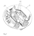
- Fig.1 equipped with that of it held elements of the circuit of the socket, is in Figures 3, 5 and 7 shown.
- the support body identified in FIGS. 3, 5 and 7 with the reference number 6 predominantly has a circular disc shape and is integrated as a molded part Executed pattern structure.
- Such molded parts are preferably based on MID technology (Molded Interconnect Devices) and then have one injection molded circuit carrier from a solderable and therefore high temperature resistant thermoplastics, such as typically polyamide (PA), Polyether sulfone (PES), polyetherimide (PEI) or liquid crystal polymer (LCP).
- the Conductor structure can be produced in a variety of ways, for example by Hot stamping or stamping or by galvanizing and etching or Laser irradiation of a simply injection molded circuit carrier or by Integration in the circuit carrier using a two-component injection molding process.
- the support body 6 on the plug part 4 of the socket forming (upward facing) side has spatial indentations.
- They are two hollow cylindrical guide elements 7 and 8 for a test button 9 a residual current test circuit or for a power button 10 of fault-protected socket and three side by side frame-shaped plug contact receptacles 11, in each of which one of three side by side plug contacts 12 of the plug part 4 is held.
- a conductor pattern structure 13 formed during the production of the support body is guided, which conductor tracks of the test circuit containing a test resistor 14 and one contains circuitry 15 required in the formation of a fault current signal.
- a Diametrically arranged to the guide element 8 not designated opening of the Carrier body are two with the connector pins 2 of the connector bridge 3 electrically conductive connected, flexible conductors 16, 17 from the underside (network side) of the support body 6 its top (consumer side) led.
- One of these two leaders will join the Insert the jumper 2 with the neutral conductor and the other with one Phase conductor of the network connected.
- the two conductors 16, 17 are on both sides of the Guide element 8 located on the consumer side of the support body arranged and are fixed with their free ends in plug-in parts 18, 19.
- two contact carriers 22 and 23 are also guided through the supporting body 6.
- Each of these two contact carriers is on the consumer side with one of each two outer of the three plug contacts 12 and on the network side with each one of two movable contacts of the contact arrangement is electrically conductive connected.
- a fixed and a moving contact form one of two Switching points 24, 25.
- the two switching points 24 and 25 and those containing them Current paths are constructed in the same way and can be by Establishing an active connection between the two external ones Plug contacts 12 are interconnected.
- the structure of the switching point 25 containing current paths can be seen from FIGS. 5 and 6.
- the reference numeral 26 is the fixed one and the Reference numeral 27 the movable contact of those located in this current path Designated switching point 24.
- the movable contact 27 is one at a free end electrically conductive leaf spring 28 attached, the other end via a Plug connection 29 is electrically conductively connected to the contact carrier 23 (FIG. 6).
- the current path containing the switching point 24 is constructed accordingly and has a leaf spring 30 corresponding to the leaf spring 28, which can be seen from FIG.
- the two ends of the leaf springs 28 and 30 carrying the movable contacts are via an insulating material bridge 31 shown in FIGS. 5 and 6 connected.
- a trigger 32 on the network side Support body 6 snapped This trigger has an actuator 33 which with closed switching points 24, 25 the insulating bridge 31 against the force which then holds tensioned leaf springs 28 and 30.
- the actuator 33 is shifted to the right and the insulating bridge 31st while simultaneously opening the switching points 24 and 25 down.
- To the Switch on is first by pressing the power button 10 in the Power button snapped reset spring 35 is charged and at the same time a driver 35 also built into the power button 19 under the Insulated bridge. After releasing the power button the relaxes Return spring 34 and the insulating bridge 31 through the driver 35 below Closing the switching points 24 and 25 and simultaneously tensioning the Leaf springs led upwards.
- the actuator 33 turns to the left moved and thereby inhibited the movement of the insulating material bridge down again.
- the operating status of the residual current circuit breaker is indicated by a Conductor lines 13 connected LED 43 displayed.
- the test button 9 contains an electrical switch conductive spring wire wound compression spring 36.
- the spring wire is with its one End 37 with one connected to a first connection of test resistor 14 Conductor of the pattern structure 13 of the test circuit electrically connected.
- the test button 9 contacts the other end 38 of the spring wire with one the second connection of the test resistor 14 connected plug contact 12.
- the two conductors 16 and 17 via the test resistor 14 short-circuited and a fault current is simulated for test purposes.
- One identified by reference number 39 and of the two flexible conductors 16 and 17 enforced sum current transformer is also on the network side to the support body 6 snapped.
- Two outputs of the summation current transformer 39 are on the network side the support body is connected to two electrically conductive connecting pieces 40, which led through the support body 6 and on the consumer side with the Conductor structure 13 and the circuit 15 are connected (Fig.5).
- modified output signals of the sum current transformer 39 are over two electrically conductive connecting pieces 41, which are also through the supporting body 6 are guided to the magnetic release 32.
- the support body 6 is another electrically conductive connection 42 out.
- This connection closes a grounded one Protective conductor of the network at and in the middle of the three plug contacts 12 is formed by two spring-loaded stirrups, one of which with the plug contact 12 and the other with the power from the plug bridge 3rd guided protective conductor is connected.
Landscapes
- Engineering & Computer Science (AREA)
- Microelectronics & Electronic Packaging (AREA)
- Details Of Connecting Devices For Male And Female Coupling (AREA)
Applications Claiming Priority (2)
| Application Number | Priority Date | Filing Date | Title |
|---|---|---|---|
| DE19936056 | 1999-07-30 | ||
| DE1999136056 DE19936056A1 (de) | 1999-07-30 | 1999-07-30 | Fehlerstromgeschützte Steckvorrichtung |
Publications (1)
| Publication Number | Publication Date |
|---|---|
| EP1073161A2 true EP1073161A2 (fr) | 2001-01-31 |
Family
ID=7916727
Family Applications (1)
| Application Number | Title | Priority Date | Filing Date |
|---|---|---|---|
| EP20000810638 Withdrawn EP1073161A2 (fr) | 1999-07-30 | 2000-07-19 | Fiche de courant à protection différentielle |
Country Status (2)
| Country | Link |
|---|---|
| EP (1) | EP1073161A2 (fr) |
| DE (1) | DE19936056A1 (fr) |
Cited By (1)
| Publication number | Priority date | Publication date | Assignee | Title |
|---|---|---|---|---|
| EP1276182A1 (fr) * | 2001-07-13 | 2003-01-15 | ABB Schweiz AG | Verrouillage pour disjoncteur de courant de défaut |
Families Citing this family (1)
| Publication number | Priority date | Publication date | Assignee | Title |
|---|---|---|---|---|
| EP2725664B1 (fr) * | 2012-10-24 | 2019-10-09 | ABB Schweiz AG | Prise protégée contre le courant différentiel |
Family Cites Families (6)
| Publication number | Priority date | Publication date | Assignee | Title |
|---|---|---|---|---|
| DE3126248A1 (de) * | 1981-07-03 | 1983-01-20 | Schupa-Elektro-GmbH + Co KG, 5885 Schalksmühle | Differenzstromschutzschalter |
| DE59400850D1 (de) * | 1993-08-31 | 1996-11-21 | Maier & Cie C | Fehlerstromgeschützte Steckdose |
| DE4420080A1 (de) * | 1993-10-19 | 1995-04-20 | Abb Patent Gmbh | Elektrisches Installationsgerät mit Zusatzmodul |
| DE9320529U1 (de) * | 1993-12-27 | 1994-08-18 | Heinrich Kopp Ag, 63796 Kahl | DI-Steckdose |
| DE4413140C2 (de) * | 1994-04-19 | 2001-09-13 | Abb Patent Gmbh | Elektrisches Installationsgerät |
| DE19529380C1 (de) * | 1995-08-10 | 1997-03-20 | Ackermann Albert Gmbh Co | Telekommunikations-Anschlußdose und Herstellungsverfahren hierfür |
-
1999
- 1999-07-30 DE DE1999136056 patent/DE19936056A1/de not_active Withdrawn
-
2000
- 2000-07-19 EP EP20000810638 patent/EP1073161A2/fr not_active Withdrawn
Cited By (1)
| Publication number | Priority date | Publication date | Assignee | Title |
|---|---|---|---|---|
| EP1276182A1 (fr) * | 2001-07-13 | 2003-01-15 | ABB Schweiz AG | Verrouillage pour disjoncteur de courant de défaut |
Also Published As
| Publication number | Publication date |
|---|---|
| DE19936056A1 (de) | 2001-02-01 |
Similar Documents
| Publication | Publication Date | Title |
|---|---|---|
| DE4438800C1 (de) | Anschlußklemmenblock mit Elektronikmodul | |
| EP2255410B1 (fr) | Barrette a bornes ou bloc de barrettes a bornes | |
| EP2790272B1 (fr) | Installation de répartition de courant ainsi que sa mise en contact et la protection des lignes qui en sortent | |
| WO2019042492A1 (fr) | Connecteur enfichable comprenant des pontages de court-circuit | |
| DE102005040348B4 (de) | Verbindungssystem mit einem elektromagnetischem Schaltgerät, insbesondere Schütz, und einem Stecker | |
| EP0847587B1 (fr) | Disjoncteur avec des transformateurs de courant et une memoire d'informations | |
| DE2547344A1 (de) | Fehlerstromschutzschalter in steckdosenausfuehrung | |
| DE202014009245U1 (de) | Schaltgerät sowie Schaltgeräteanordnung | |
| EP0709919B1 (fr) | Barrette d'interconnexion pour repartition transversale de puissance | |
| CH681260A5 (fr) | ||
| DE102006031129A1 (de) | Gerätesystem mit auf einer Tragschiene montierten elektrischen Gerätemodulen und in der Tragschine angeordneter BUS-Leitung | |
| DE102013111571A1 (de) | Gerätegehäuse, Elektronikgeräte und Steckkontaktträger | |
| DE10030954A1 (de) | Stromverteiler | |
| EP0316259A2 (fr) | Bloc de connexion formé de plusieurs sous-blocs | |
| EP1073161A2 (fr) | Fiche de courant à protection différentielle | |
| DE202011102353U1 (de) | Sicherungsanordnung insbesondere für ein Kraftfahrzeug-Bordnetz | |
| EP0641045B1 (fr) | Prise de courant à protection différentielle | |
| DE102004043468A1 (de) | Schaltgerät mit steckbaren Anschlüssen | |
| DE10361452A1 (de) | Anordnung zum Befestigen von elektrischen und/oder elektronischen Bauteilen, insbesondere Leistungsbauteilen, an einer Platine und Gehäuse hiermit | |
| DE19624511C2 (de) | Kontaktschiene mit Steckerbuchsen sowie Steckmodul mit einer solchen Kontaktschiene | |
| DE202014101581U1 (de) | Steckanordnung | |
| EP0453918B1 (fr) | Module auxiliaire pour appareil de commutation électromagnétique | |
| DE202011002884U1 (de) | Sicherungsanordnung | |
| DE3313587C2 (de) | Geräte-Steckverbinder mit Spannungswähler | |
| EP0641044B1 (fr) | Disposition de contact pour une prise de courant à protection différentielle |
Legal Events
| Date | Code | Title | Description |
|---|---|---|---|
| PUAI | Public reference made under article 153(3) epc to a published international application that has entered the european phase |
Free format text: ORIGINAL CODE: 0009012 |
|
| AK | Designated contracting states |
Kind code of ref document: A2 Designated state(s): AT BE CH CY DE DK ES FI FR GB GR IE IT LI LU MC NL PT SE |
|
| AX | Request for extension of the european patent |
Free format text: AL;LT;LV;MK;RO;SI |
|
| RAP1 | Party data changed (applicant data changed or rights of an application transferred) |
Owner name: ABB SCHWEIZ AG |
|
| STAA | Information on the status of an ep patent application or granted ep patent |
Free format text: STATUS: THE APPLICATION IS DEEMED TO BE WITHDRAWN |
|
| 18D | Application deemed to be withdrawn |
Effective date: 20050201 |